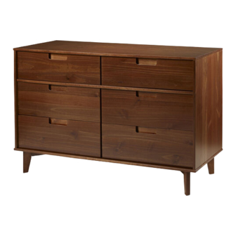
Walker Edison BR6DSLDR Assembly Instructions Manual
Hide thumbs
Also See for BR6DSLDR:
- Assembly instructions manual (11 pages) ,
- Assembly instructions manual (13 pages)
Advertisement
Quick Links
Item # : BR6DSLDR
Assembly Instructions
Please visit our website for the most current instructions, assembly tips, to report damage
or request parts. www.walkeredison.com
Revised 05/2019
Copyright © 2018, by Walker Edison Furniture Co., LLC, All rights reserved.
P.1
Advertisement

Summary of Contents for Walker Edison BR6DSLDR
- Page 1 Item # : BR6DSLDR Assembly Instructions Please visit our website for the most current instructions, assembly tips, to report damage or request parts. www.walkeredison.com Revised 05/2019 Copyright © 2018, by Walker Edison Furniture Co., LLC, All rights reserved.
- Page 2 and hammmer VIII. Maintenance Guide To maintain long term performance and easy gliding of your solid wood drawers, we recommend applying wax to the wooden guide rails. 1. Bee's wax is recommended or Paraffin wax from a standard candle can be used. 2.
- Page 3 The side drawer with WARNING LABEL, should be mounted in highest drawer. Part# Description Part# Description Top panel Right drawer side Drawer bottom Right side panel Left side panel Drawer back Bottom panel Small drawer front Right crossbeam foot Large left drawer side Left crossbeam foot Large right drawer side Back panel...
- Page 4 Ø8*30mm Wooden dowel Ø8*20mm Wooden dowel Screw Ø4*25mm Ø3,5*30mm Screw Screw Ø4,0*40mm Ø10*10 Nail Ø7*60mm Screw Hex Key Glue “H” Profile 1272mm Wall anchor Washer Ø6mm Tape measure and hammer recommended for assembly (not included)
- Page 5 Step 1 Ø8*30mm Please assemble on into parts (2, 3, 5, 6, 11,12, 13, 16, 17, 20, 21). a clean soft surface Ø8*20mm to avoid damage. into part (9, 22).
- Page 6 Step 2 Attach part (20) to parts (2,3,21)using screw (D) Ø3,5*30mm Step 3 Ø4,0*40mm...
- Page 7 Step 4 Ø3,5*30mm Step 5 Ø4,0*40mm Ø7*60mm...
- Page 8 Step 6 o attach part (1) to body Ø3,5*30mm Name and address of Step 7 the supplier and date of production. Ø10*10 1272mm...
- Page 9 Step 8 FRONT Ø4*25mm parts (22) to parts (2,3) parts (9) to BOTH sides of part (21) Step 9 FRONT Ø8*30mm...
- Page 10 Step 10 Ø3,5*30mm Ø3,5*30mm Step 12 Ø8*30mm Insert wood dowel (A) on the P.10...
- Page 11 Step 13 Wall anchor and hardware are included with this product. Please make sure hardware is suitable for your walls before types of anchors. 1 st Ø6mm Attach part (K) Back panel in the frame of superior panel unit. Insert part (M) in the hole. 2 nd Wall Wall...


Need help?
Do you have a question about the BR6DSLDR and is the answer not in the manual?
Questions and answers