Table of Contents
Advertisement
Quick Links
Advertisement
Table of Contents
Troubleshooting

Summary of Contents for Bell VFM60 Series
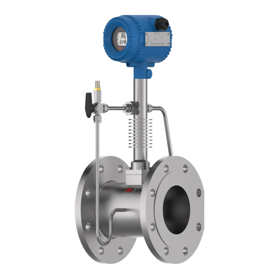
- Page 1 VFM60 Series Vortex Flowmeter Introduction Manual...
-
Page 2: Table Of Contents
VFM-60 Vortex Flowmeter CONTENTS Support ..............................2 Place an order ..........................2 1 General ............................. 4 1.1 Model Number and General Specification ................4 1.2 Packing List........................... 4 Storage........................... 4 1.4 Hazardous Area Installation: ....................4 1.5 Measuring principle: ......................5 2 Installation ............................ - Page 3 VFM-60 Vortex Flowmeter 6.5 The sequence of the float date bytes of instrument ............31 6.6 Modbus error reponse ......................32 6.7 Examples of communication ....................33 7 Introduction of HART communication protocol ................34 7.1 HART commands ........................ 34 7.1.1 Command 0:Read transmitter unique identifier ............
-
Page 4: General
VFM-60 Vortex Flowmeter 1 General Every VFM60 vortex flowmeter will be carefully inspected before delivered to users. Please carefully check if there is any damage on the package and product when you received them Please check if the package contains all the accessories according to 1.2 or your purchase order. Please make sure the person in charge of this device has carefully read this manual and understand its descriptions. -
Page 5: Measuring Principle
VFM60 series digital vortex flowmeter is designed to provide most reliable performence. This series of vortex flowmeter is designed on PA60 plateform. Every part utilized is universal for all VFM60 series products. The circuit boards use signal isolation and self-diagnose technology. VFM60 series utilize spectrum analizing signal process technology, which ensured lower under measuring limit and better turndown ratio. -
Page 6: Installation
VFM-60 Vortex Flowmeter 2 Installation 2.1 Find Most Suitable Location (1) Ambient temperature Please avoid installing the flowmeter at a location where temperature could dramaticly changes. If the meter is under heavy heat radiation, please implement effective heat insulation and venting method. (2) Atomosphere Please do not install the meter at a locaition where the atomosphere contains a high level of corrosive substance. - Page 7 VFM-60 Vortex Flowmeter Upsized Curve pipeline Dual-curve pipeline when medium over 150° C(302° F), recommend flow meter installs Steam measurement vertical to the pipeline (as picture), or (Only allow install on a horizontal pipe, flow installation in meter recommend to install in the shadow areas) shadow areas.
- Page 8 VFM-60 Vortex Flowmeter Pressure sensor:2~7D downstream of flowmeter Temperature sensor: 1~2D downstream of pressure sensor Roots blower or piston blower or air compressor in upstream Roots blower or piston blower or air compressor or pump in upstream, could cause vibration of the fluid itself. To eliminate this vibration, please install a orifice plate or a upsized pipe at about 25D upstream the meter.
- Page 9 VFM-60 Vortex Flowmeter Gaskets should not get into the pipeline Heat insulation: If the fluid is in high temperature, the heat insulation material should not cover the heat dissipation hole on flow meter Pipe cleaning: If thepipeline need to be cleaned, please use a subtitied pipe to replace the flowmeter...
-
Page 10: Wiring
VFM-60 Vortex Flowmeter 3 Wiring VFM60 vortex flowmeter has 2 different terminal boards, the 5-terminals board and the 12 terminals board, please reference to picture 3.1 and 3.2 below. V+ V- Picture 3.1 5-terminals board Picture 3.2 12-terminals board is pulse output terminal. A, B are “+” and “-” for On above boards, V+ and V- are for power. -
Page 11: Wiring For 5-Terminal Board
VFM-60 Vortex Flowmeter 3.1 Wiring for 5-terminal board 3.1.1 Wiring for 3 wire pulse output 3-wire pulse output require a power source of 13.5~42VDC. VFM use a current pulse output with 50% duty ratio. If the pulse reciving instrument require voltate pulse, please add a resistor between “... -
Page 12: Wiring For Rs485
VFM-60 Vortex Flowmeter 3.1.3 Wiring for RS485 Picture 3.5 Wiring for RS485 3.2 Wiring for 12-terminal board 3.2.1 Wiring for 3 wire pulse output 3-wire pulse output require a power source of 13.5~42VDC. VFM use a current pulse output with 50% duty ratio. -
Page 13: Wiring For 4 Wire 4~20Ma
VFM-60 Vortex Flowmeter 3.2.2 Wiring for 4 wire 4~20mA Picture 3.7: Wiring for 4-wire 4~20mA 3.2.3 Wiring for 4 wire HART@4~20mA When power source is 24VDC, the max load for 4~20mA analog is 500ohms. Picture 3.8: Wiring for 4-wire HART@4~20mA Rev1.3 Date:24/04/2020 User’s Manual... -
Page 14: Wiring For Rs485
VFM-60 Vortex Flowmeter 3.2.4 Wiring for RS485 Picture 3.9: Wiring for RS485 3.3 Shell grounding and elimination of interference In VFM60 digital vortex flowmeter the power supply of signal processing circuit is transferred from outside power supply by a isolation type DC-DC transmitter with advanced grounding technology. The field frequency interference can be isolated well. -
Page 15: Display
VFM-60 Vortex Flowmeter Picture 3.10 Introduction for wiring 4 Display VFM60 digital vortex flowmeter provide local display and setting, can display several variables on the local multi-funcational LCD display. The convertor also have 3 button so clients can do setting on it. - Page 16 VFM-60 Vortex Flowmeter Picture 4.1 LCD display The LCD display has 2 areas to display the content, the upper row, the lower row. The upper row displays the flow rate/mass flow/standard flow rate. Below the upper row shows the unit of the variable displayed in upper row.
-
Page 17: Unit Of The Variable Displayed
Density Chart 4.1 The displayed units Remark: Clients can select 4.3 Three button setting VFM60 series digital vortex flowmeter has three buttonS on the top of the displayer, which are: (will be mentioned as “L-R button” below), (will be mentioned as “U-D button”... -
Page 18: Total Flow Displaying
VFM-60 Vortex Flowmeter Picture 4.5 buttons When under working, use “U-D button” to switch the displaying content, use “L-R button” can switch to the left and right digits of total flow. “Enter button” is to dispay the entire digits of total flow directly. -
Page 19: Status
VFM60 series digital vortex flowmeter have digigal setting and code setting. Use code setting to set parameters such as fluid type, compensation type and output signal. Use digital setting to set parameters related to a number, such as pipe size, flow range, factor. -
Page 20: Digital Setting
VFM-60 Vortex Flowmeter same time. Please reference to picture 5.1. Picture 5.1 enter and quit code setting When in code setting, the first row will display the reference number fo the code setting, and the lower row will display the contents of this parameter. The digit that is flashing is the digit under setting. -
Page 21: Setting List
VFM-60 Vortex Flowmeter Picture Enter or quit digital setting When in digital setting, the first row will display the reference number of the digital setting, and the lower row will display the contents of this parameter. The digit that is flashing is the digit under setting. - Page 22 VFM-60 Vortex Flowmeter Code setting Item Code Description of code address Steam Fluid Liquid Volume flow display, density compensation Density preset Pressure compensation (for saturated steam pressure not larger than 20Mpa Temperature compensation (For saturated steam) Temperature and pressure compensation (For superheated steam) Density compensation ρ=A+BP (Pressure compensation)
- Page 23 VFM-60 Vortex Flowmeter 1200 even parity 1 stop bit 2400 no parity 1 stop bit 2400 even parity 1 stop bit 4800 no parity 1 stop bit 4800 even parity 1 stop bit 9600 no parity 1 stop bit 9600 even parity 1 stop bit 19200 no parity 1 stop bit 19200 even parity 1 stop bit 1200 odd parity 1 stop bit...
- Page 24 VFM-60 Vortex Flowmeter ℃ ℉ Temperature unit 00:No right digits for total flow Right digits number for total flow 00~05 01~05:1~5 right digits for total flow Flow rate 1st row display parameter percentage of flow rate to flow range No display Total flow Temperature lower row display parameter...
- Page 25 VFM-60 Vortex Flowmeter Times of over totalflow 00~99 For reading only Restore to backup date Restore to backup date Save setting backup Save current setting for backup Note: 1) If the unit of flow rate is changed or measurement changed from flow rate to mass flow, users can reset the total flow to 0 or record the current total flow 2) Total flow=(time of over total flow)* (max display of total flow)+(current total flow reading) Chart 5.2 Digits settingaddress...
-
Page 26: Example Of Setting
VFM-60 Vortex Flowmeter starting frequency Resonance frequency (0,999999] For high speed steam measure use ending frequency Relative density of For calculation of compressibility factor of [0.55,0.90] compressibility factor natural gas For calculation of compressibility factor of [0,0.1] mol% of N2 and H2 natural gas,eg.if 1%, please input 0.01 For calculation of compressibility factor of [0,0.3]... -
Page 27: Instruction Of Rs485 Modbus Communication
VFM-60 Vortex Flowmeter To set a new password, users have to input the correct password twice, the password will become effective only if the both inputs are the same; or users have to input again. If the power is off during a password setting process, the password will be 2000 as default. - Page 28 VFM-60 Vortex Flowmeter 24~25 Total flow Read only Float The displayable date including flow rate, frequency, pressure, temperature, density and total flow, if the meter do not have density compensation, then the reading of pressure and temperature will both be 0. The date of the parameters in above chart can be read by using function code 03 according to the address above and shifting.
-
Page 29: Commends
VFM-60 Vortex Flowmeter Digital setting address is as below. Chart 6.3 Address of digital setting Register Usage Restriction of Nature Date modification type 2000~2001 D001 Max pressure -1e5~1e6 Read/Write Float 2002~2003 D002 Min pressure -1e5~1e6 Read/Write Float 2004~2005 D003 Max temperature -1e5~1e6 Read/Write Float... -
Page 30: Calculation Of Crc Parity Code
VFM-60 Vortex Flowmeter CRCH :CRC parity code higher CRCL : CRC Parity code lower CRCH :CRC parity code higher Note: To read a float date, the quantity of the register address and its value have to be even, or reponse will be error. Function code 04 –... -
Page 31: The Float Date Format Of The Instrument
VFM-60 Vortex Flowmeter 00 : Register address higher N3 CRC move 1 bit right , if move out is 1 bit 01 : Register address lower N4 CRC=CRC XOR A001H 00 : Register quantity higher N5 if move out is 0 , CRC=CRC 04 : Register quantity lower N6 Move right for 8 times to finish the N1 calculation N7 …... -
Page 32: Modbus Error Reponse
VFM-60 Vortex Flowmeter registers come first. eg: 100=0x00,0x00,0x42,0xc8 -100=0x00,0x00,0xc2,0xc8 4: HL_HH_LL_LH the higher 16 bytes registers come first, the lower 8 bytes within the 16 bytes registers come first. eg: 100=0xc8,0x42,0x00,0x00 -100=0xc8,0xc2,0x00,0x00 6.6 Modbus error reponse When the host sends a command and asks for a correct reponse, one of below three is going to happe: 1) If the command from the host is correct and processable, the flow meter will give a correct reponse. -
Page 33: Examples Of Communication
VFM-60 Vortex Flowmeter Reponse The flow meter will take a long while to process the command. So reponse this error code to prevent the host from processing a overtime command. Flowmeter To advise the host that the flowmeter is processing a command which busy will takes a long time. -
Page 34: Introduction Of Hart Communication Protocol
VFM-60 Vortex Flowmeter 44 9D 1E 3F(total flow in float=1256.94) (CRCL) (CRCH) 7 Introduction of HART communication protocol 7.1 HART commands 7.1.1 Command 0:Read transmitter unique identifier Command formate Return to the expension device type code, version number and identification number Request: None Response: Byte 0:... -
Page 35: Command 2:Read Primary Variable's Current And Percentage Value
VFM-60 Vortex Flowmeter Remark:The unit code is 75:kg/hour, 19:m3/hour. Set primary command to flow rate. Test of command: Send command 1: FF FF FF FF FF 82 9A 1A AD 18 8C 01 00 3A ;to read the IEEE754 float value of primary variable. -
Page 36: Command 6:Write Polling Address
VFM-60 Vortex Flowmeter Tertiary variable is frequency. The unit is Hz; Quaternary variable is temperature. The unit is 32: ℃; Test of command: Send command 3:FF FF FF FF FF 82 9A 1A AD 18 8C 03 00 38; to read dynamic variables Receive command 3:FF FF FF FF FF 86 9A 1A AD 18 8C 03 1A 00 00 40 80 00 00 13 00 00 00 00 2B 48 33 5A 4B 26 00 00 00 00 20 00 00 00 00 B2 7.1.5 Command 6:Write polling address... -
Page 37: Command 12:Read Message
VFM-60 Vortex Flowmeter Byte 6: Software revision level Byte 7: Hardware revision level Byte 8: Flags, none defined at this time. Byte 9-11: Device identification number Test of command: Send command 11: FF FF FF FF FF 82 9A 1A AD 18 8C 0B 00 30 ; Read relevant info of the device such as unique identifier associated with tag Receive command 11: FF FF FF FF FF 86 9A 1A AD 18 8C 0B 0E 00 00 FE 1A 1A 05 05 00 00 00 00 AD 18 8C FD... -
Page 38: Command 14:Read Primary Variable Sensor Information: Device Serial Number And Limits
VFM-60 Vortex Flowmeter 7.1.9 Command 14:Read primary variable sensor information: device serial number and limits Command formate: Read device information Request: None Response: Byte 0-2: Sensor serial number MSB, 24-BIT unsigned integer Byte 3: Flow rate unit Byte 4-7: Upper sensor limit of flow rate Byte 8-11: Lower sensor limit of flow rate Byte 12-15: Minimum span of flow rate Test of command:... -
Page 39: Command 16: Read Final Assembly Number
VFM-60 Vortex Flowmeter 7.1.11 Command 16: Read final assembly number Command formate: Read final assembly number. Request: None Response: Byte 0-2: Final assembly number Test of command: Send command 16:FF FF FF FF FF 82 9A 1A AD 18 8C 10 00 2B; Read final assembly number Receive command 16: FF FF FF FF FF 86 9A 1A AD 18 8C 10 05 00 00 A8 36 81 35 7.1.12 Command 17: Write message Command formate:... -
Page 40: Command 19: Write Final Assembly Number
VFM-60 Vortex Flowmeter Receive command 18:FF FF FF FF FF FF 86 9A 1A AD 18 8C 12 17 00 00 00 00 00 00 00 00 00 00 00 00 00 00 00 00 00 00 00 00 00 00 00 3A 7.1.14 Command 19: Write final assembly number Command formate: Write final assembly number... -
Page 41: Command 36: Write Primary Variable Upper Limit Value
VFM-60 Vortex Flowmeter Byte 5-8: Primary variable lower range limit, IEEE 754 Response: Byte 0: Primary variable upper and lower range value unit code Byte 1-4: Primary variable upper range limit, IEEE 754 Byte 5-8: Primary variable lower range limit, IEEE 754 Test of command: Send command 35: FF FF FF FF FF 82 9A 1A AD 18 8C 23 09 13 40 00 00 00 40 00 00 00 02;... -
Page 42: Command 40: Enter/Exit Primary Variable Current Mode
VFM-60 Vortex Flowmeter NONE Test of command: Send command 37: FF FF FF FF FF 82 9A 1A AD 18 8C 25 00 1E; Write the primary variable lower limit to current primary variable value. Receive command 37: FF FF FF FF FF 86 9A 1A AD 18 8C 25 02 00 00 18 7.1.19 Command 40: Enter/Exit primary variable current mode Command formate: Device is set to fixed primary variable current, when primary variable is 0, means to exit primary... -
Page 43: Command 46: Trim Primary Variable Current Dac Gain
VFM-60 Vortex Flowmeter 7.1.21 Command 46: Trim primary variable current DAC gain Command formate: Trim primary variable AO gain, so the current current value is accurate set to its max value. Before implementing this command, use command 40 to set current to accurate primary variable AO max value. -
Page 44: Replace A Transmitter Circuit Boards
VFM-60 Vortex Flowmeter Picture 8.1 Reverse the transmitter front and back 8.2 Replace a transmitter circuit boards 1) Please make sure the power is off before replacing the transmitter. 2) Remove the front cover. 3) Loose the 4 screws on the circuit boards, than can take the boards out a little. 4) Remove all the plugs on the circuit board.then remove the circuit board away 5) Put the new circuit board in and put the plug on 6) Tighten the 4 screws on the board, tighten the front cover... -
Page 45: Troubleshooting And Repair
VFM-60 Vortex Flowmeter none-explosive environment. Please make sure the environment the flowmeter in can meet the requirement of the certificate. When power is wired, please make sure the front and rear cover is closed properly. 9.2 Troubleshooting and repair Symptom Reason Trouble shooting repair... -
Page 46: Self-Diagnose Funcstion
VFM-60 Vortex Flowmeter Straight pipe length not enough or the inner Check the straight pipe length diameter of flowmeter Re-locate the flowmeter and the diameter of the pipelien pipe body do not match the pipeline There is heavy vibration Sense the vibration on the pipe Tighten the pipeline where on the pipe line line by touch it with hand... -
Page 47: Remark
VFM-60 Vortex Flowmeter Err-014 Reset code setting failed Check EEPROM Err-015 Reset digital setting failed Check EEPROM Err-016 Read total flow error Check EEPROM Err-017 Temperature calibration setting is wrong Check the record of temperature calibration Err-018 pressure calibration setting is wrong Check the record of pressure calibration Err-020 Flow rate limit setting is incorrect... -
Page 48: Appendix
VFM-60 Vortex Flowmeter Appendix Specification □ Accuracy Variables For gas and steam Liquid Re 20000 0.75% Re 20000 ) ) Flow rate(m3/h) RD( RD( 10000 Re 20000 10000 Re 20000 (... - Page 49 VFM-60 Vortex Flowmeter □Temperature range − ℃ ℃ 180 ~100 Low temperature version − ℃ ℃ 40 ~150 Normal temperature version − ℃ ℃ 40 ~250 Medium temperature version − ℃ ℃ 40 ~350 High temperature version □Pressure range Available pressure rating includes 1.6Mpa, 2.5Mpa, 4.0Mpa, 6.4Mpa. If the application requires a higher-pressure rating, please contact us to check the possibility.
- Page 50 VFM-60 Vortex Flowmeter 340.5 381.5 521.5 Remark: The flange O/D, screwholes distance, flange thickness,screwhole diameter and screw qty are for the counter flanges, unit in mm. Counter flanges,screw and bolts,gaskets are usually along with package except customer do not need them.
- Page 51 VFM-60 Vortex Flowmeter 190.5 152.4 24.3 190.5 24.3 215.9 24.3 22.2 241.3 25.9 22.2 298.5 22.2 30.6 25.4 412.7 593.7 593.7 431.8 32.2 25.4 445.4 626.4 626.4 Dimension of ANSI CL150 flanged version W(Flange C(flange H (Meter H (Meter H (Meter K(Flange L(Pipe screwhol...
- Page 52 VFM-60 Vortex Flowmeter 412.7 593.7 593.7 445.4 626.4 626.4 Dimension of DIN PN16 flanged version W(Flange C (flange H (Meter H (Meter H (Meter K(Flange L(Pipe n(scre Size screwhole thickness (screwhole height) height) height) O/D) length) w qty) distance) diameter) 150dgrC 250dgrC 350dgrC...
- Page 53 VFM-60 Vortex Flowmeter 412.7 593.7 593.7 445.4 626.4 626.4 Dimension of DIN PN40 flanged version W(Flange H (Meter H (Meter H (Meter K (Flange L(Pipe C(flange n(screw Size screwhole (screwhole height) height) height) O/D) length) thickness) qty) distance) diameter) 150dgrC 250dgrC 350dgrC 300.5...
- Page 54 VFM-60 Vortex Flowmeter 412.7 593.7 593.7 445.4 626.4 626.4 Dimension of JIS 20K flanged version Remark: Flanged version do not contains screws and bolts in the package unless customer need to purchase from us. We also have flanged type in other standard and pressure rating. Please check with us if you require flanged version other than what we provided □...
- Page 55 VFM-60 Vortex Flowmeter □ Size and dimension for multi-variable flanged type VFM60MV Flanged type 150 dgrC version VFM60MV Flanged type 250 dgrC version W(Flange K(Flange L(Pipe C (flange (Meter (Condensation (Meter (Condensation (Meter (Condensation Size screwhole (screwhole (screw (Condensation O/D) length) thickness) height)
- Page 56 VFM-60 Vortex Flowmeter W(Flange K(Flange L(Pipe C (flange (Meter (Condensation (Meter (Condensation (Meter (Condensation Size screwhole (screwhole (screw (Condensation O/D) length) thickness) height) piep height height) piep height height) piep height distance) diameter) qty) piep length) 150dgrC 150 dgrC) 250dgrC 250 dgrC) 350dgrC 350 dgrC)
- Page 57 VFM-60 Vortex Flowmeter W(Flange K(Flange L(Pipe C (flange (Meter (Condensation (Meter (Condensation (Meter (Condensation Size screwhole (screwhole (screw (Condensation O/D) length) thickness) height) piep height height) piep height height) piep height distance) diameter) qty) piep length) 150dgrC 150 dgrC) 250dgrC 250 dgrC) 350dgrC 350 dgrC)
- Page 58 VFM-60 Vortex Flowmeter W(Flange K(Flange L(Pipe C (flange (Meter (Condensation (Meter (Condensation (Meter (Condensation Size screwhole (screwhole (screw (Condensation O/D) length) thickness) height) piep height height) piep height height) piep height distance) diameter) qty) piep length) 150dgrC 150 dgrC) 250dgrC 250 dgrC) 350dgrC 350 dgrC)
- Page 59 VFM-60 Vortex Flowmeter □ Size and dimension for insertion type Size H (High) 1000 □ Size and dimension for remote converter Rev1.3 Date:24/04/2020 User’s Manual 59 / 59...