
Related Manuals for BANDELIN SONOPULS HD 5020


Summary of Contents for BANDELIN SONOPULS HD 5020
- Page 1 Instructions for use Ultrasonic homogeniser Valid for: SONOPULS HD 5020 SONOPULS HD 5050 SONOPULS HD 5100 SONOPULS HD 5200 SONOPULS HD 5400 51846-000 en/2022-07 Dokument: 51846-000 Sprache: en Version: 2022-07...
- Page 2 © 2022 1 2 GmbH & Co. KG, Heinrichstr. 3–4, 12207 Berlin, Ger- many Phone: +49 30 76880-0, Fax: +49 30 7734699, info@bandelin.com Certified in accordance with ISO 9001 and ISO 13485 2/36 51846-000 en/2022-07...
-
Page 3: Table Of Contents
Table of contents Table of contents About this operating manual ........Safety . - Page 4 Table of contents 5.4.2 Creating a program ......... . 5.4.3 Activating and deactivating a program .
-
Page 5: About This Operating Manual
• If you pass this ultrasound bath on to others, please enclose these instruc- tions for use. • Contact your specialist dealer or BANDELIN if any of your questions are not answered in these instructions for use. Information on service can be found in chapter 6.3 Repair. -
Page 6: Safety
Safety 2 Safety 2.1 Use of the device The device is used in laboratories, clinics and in industrial research. It performs diverse tasks during sample preparation in Quality Assurance, scientific experi- ments, analyses, and in pilot or short-series manufacture. Examples of applications are: •... -
Page 7: Danger Of Electric Shock
Safety 2.4 Danger of electric shock The device is an electrical device. Failure to follow safety rules can result in a life- threatening electric shock. • Protect the device from moisture and wetness. Keep the surfaces and the touchscreen clean and dry. •... -
Page 8: Harmful To Health Due To Ultrasound Noise
Safety 2.7 Harmful to health due to ultrasound noise The ultrasound noise typical of the process can be perceived as very unpleasant. Remaining within a radius of 2 m for an extended period of time may cause dam- age to health. •... -
Page 9: Design And Function
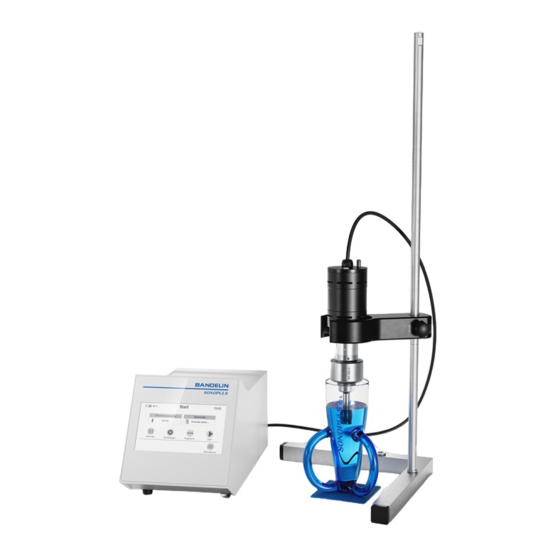
Design and function 3 Design and function 3.1 Overview Fig. 1 Overview of the device 1 Ultrasound generator 2 Touchscreen 3 Connector for ultrasonic converter 4 LAN connection 5 USB Type B port 6 USB Type A port 7 Mains switch 8 Cold device socket with fuse holder 9 Ultrasonic converter 10 Start/Stop key... -
Page 10: Symbols And Buttons On The Touch Screen
Design and function 3.2 Symbols and buttons on the touch screen Return to previous screen Reset values Confirm/Save Go to startup screen Calling up the screen help Start Pause Stop 3.3 Function The device transforms the absorbed grid energy into high-frequency energy. The ultrasonic converter converts the high-frequency energy into ultrasound. -
Page 11: Preparation For Operation
Preparation for operation 4 Preparation for operation 4.1 Set up homogeniser 1. Place the ultrasonic generator on a firm, level and dry surface. 2. Screw the probe onto the standard horn or booster horn, or to the ultrasonic converter (HD 5020/5050); see 4.2 Mounting/removing the probe. 3. -
Page 12: Mounting/Removing Standard Horn Or Booster Horn
Preparation for operation 20 mm 20 mm Fig. 2 Loosen (A) and tighten (B) the probe A video on loosening and attaching the probe is available: https:/ /www.youtube.com/watch?v=hjTC_cvO4kQ 4.3 Mounting/removing standard horn or booster horn NOTICE Damage to the ultrasonic converter If the ultrasonic oscillating system in the housing of the ultrasonic converter twists, the ultrasonic converter will be damaged. - Page 13 Preparation for operation Fig. 3 Removing standard horn or booster horn 1. Unscrew the standard horn or booster horn by hand. 2. Clean the mounting surfaces of the ultrasonic converter and the standard horn or booster horn, as well as the thread of the threaded pin, with a lint- free cloth soaked in alcohol.
-
Page 14: Switching The Device On And Off
Preparation for operation 4.4 Switching the device on and off Switching on the ultrasonic homogeniser for the first time Allow the device to stand for 2 hours at its operating location before switching it on so that it can adapt to the climatic conditions. 1. -
Page 15: Operation
Operation 5 Operation 5.1 Immersion depth notes The recommended immersion depth for probes is 10 ... 20 mm, to prevent the aspiration and mixing-in of air. If mixed-in air is desired, the probe may be immersed just a few millimetres. When producing emulsions, the probe should be immersed to the height of the surface separating the liquids to be mixed. -
Page 16: Enter Sonication Time
Operation 5.2.2 Enter sonication time 1. On the startup screen, tap "Parameters". 2. Tap on "Time". 3. Make the desired settings for the sonication time. » A time setting is only effective if "Continuous operation" is not activated. 4. Confirm your entry with the "Confirm/Save" button. 5.2.3 Set pulsation The sonication can be switched on continuously or in pulses. -
Page 17: Start Sonication
Operation 5.3 Start sonication Requirement • The probe tip is immersed in the sonicating medium; see 5.1 Immersion depth notes. 1. On the startup screen, tap the "Start" button. » The “Sonication” screen appears. » The preselected sonication parameters are displayed; see 5.2 Preselect parameters for sonication 2. -
Page 18: Activating And Deactivating A Program
Operation 5.4.3 Activating and deactivating a program Activating a program 1. On the startup screen, tap "Programs". » The "Programs" overview screen is shown. 2. Tap on a program number. 3. If a screen with the summary of the program parameters appears, tap "Edit". 4. -
Page 19: Starting A Program
Operation 5.4.4 Starting a program To start set and activated programs in the specified sequence, proceed as fol- lows: Requirement • The probe tip is immersed in the sonicating medium; see 5.1 Immersion depth notes. • At least one program is activated and a space is assigned in the sequence; see 5.4.3 Activating and deactivating a program. -
Page 20: Creating Documentation
Operation 5.5 Creating documentation Activate logging Information The logs are also generated without connection of a USB device. They can be exported later, as long as the device has not been switched off in the meantime. The logs are lost when the device is switched off. 1. -
Page 21: Set Settings
Operation 5.6 Set settings 5.6.1 Adjusting the button function You can specify whether the button on the ultrasonic converter must be held down in order to activate the ultrasound, or whether it is switched on and off by pressing briefly. 1. -
Page 22: Set Sleep Mode
Operation 5.6.5 Set sleep mode To save energy, the device will go into a sleep mode after a while. The touch- screen switches off in sleep mode. Wake up the device by tapping the touch- screen. The time of inactivity after which the sleep mode starts can be adjusted. 1. -
Page 23: Troubleshooting A Malfunction
Operation 5.7 Troubleshooting a malfunction Proceed according to the message on the touchscreen to rectify the fault. The following table contains faults that are not displayed on the touchscreen. Error Possible Troubleshooting causes Device cannot be Mains cable loose • Check the plug connection for firm positioning. -
Page 24: Maintenance
Maintenance 6 Maintenance 6.1 Cleaning the device • Disconnect the device from the mains before cleaning. • Wipe the device with a lint-free damp cloth. You can use a commercially avail- able cleaning agent without abrasive additives. • If necessary, the surfaces can be treated with a surface disinfectant. •... -
Page 25: Repair
Fill out the form and attach it to the outside of the packing so that it is clearly visible. Acceptance will be refused without a completed form. Send the device to the following address: BANDELIN electronic GmbH & Co. KG Heinrichstr. 3-4 12207 Berlin Germany +49 30 76880-13 service@bandelin.com... -
Page 26: Disposal
Disposal 7 Disposal WARNING Health risk due to contaminated ultrasonic bath – Decontaminate the ultrasonic bath before disposal if it has come into contact with hazardous substances. – Also decontaminate accessories before disposal. Dispose of the ultrasonic bath properly as electronic waste if it can no longer be used. -
Page 27: Device Information
Device information 8 Device information 8.1 Technical data Ultrasound generator Type: GM 5000 Mains supply: 100-240 V~ ±10% 50/60 Hz Current consumption: 90 V AC/115 V AC Max. 5.2 A Current consumption: 230 V AC 2.6 A Fuses: F 6.3 A Protection class: Ultrasonic frequency: 20 kHz ±500 Hz, 40 kHz ±500 Hz... - Page 28 Device information Ultrasonic converter UW 5020 Ultrasonic frequency: 40 kHz Weight: 0.5 kg Dimensions: ∅ 50 mm × 150 mm Degree of protection: IP 30 Ultrasonic converter UW 5050 Ultrasonic frequency: 20 kHz Weight: 0.6 kg Dimensions: ∅ 50 mm × 185 mm Degree of protection: IP 30 Ultrasonic converter UW 5100, UW 5200...
-
Page 29: Ambient Conditions
Device information 8.2 Ambient conditions Overvoltage category: Degree of contamination: Permissible ambient temperature: 5 - 40 °C Permissible relative humidity up to 80 % (non-condensing) 31 °C: Permissible relative humidity up to 50 % (non-condensing) 40 °C: Altitude < 2000 m above sea level For indoor operation only 8.3 CE conformity The device satisfies the CE-marking criteria of the European Union:... -
Page 30: Accessories
Accessories 9 Accessories 9.1 Available probes Ultrasonic converter UW 5020 Probe Ø sound emitting Sonication Max. amplitude surface [mm] volume [ml] [μm MS 1.5 0.1 … 10 MS 2.0 0.25 ... 20 MS 2.5 0.5 ... 25 Ultrasonic converter UW 5050 Probe Ø... - Page 31 Accessories Ultrasonic converter UW 5200 with standard horn SH 200 G Probe Ø sound emitting Sonication Max. amplitude surface [mm] volume [ml] [μm TS 103 5 … 90 TS 104 5 … 100 TS 106 10 … 350 TS 109 10 …...
-
Page 32: Optional Accessories
Accessories 9.2 Optional accessories Stand HG 40, for correct, variable positioning of the ultrasonic converter. Sound proof box LS 40 reduces noise emissions by approx. 30 dB(AU). Temperature sensor TM 5000, Pt 1000, sample temperature monitoring. For further accessories, please refer to the product information (appendix to these Instructions for use). -
Page 33: Optional Tool
Accessories 9.3 Optional tool Double open-end spanner MS 8/10 Mounting/disassembling of the probes for HD 5020 Open-end spanner MS 10 Mounting/disassembling of the probes for HD 5050/5100/5200 Open-end spanner MS 22 Mounting/disassembling of the probes for HD 5400 Sickle spanner HS 25/28 For holding UW 5020/5050 in place during mounting/disassembling of the probes Sickle spanner HS 40/42... - Page 34 Accessories 34/36 51846-000 en/2022-07...
- Page 35 Accessories 35/36 51846-000 en/2022-07...
- Page 36 1 2 GmbH & Co. KG Heinrichstr. 3–4 12207 Berlin Germany Phone: +49 30 76880-0 Fax: +49 30 7734699 info@bandelin.com www.bandelin.com 51846-000 en/2022-07...
Need help?
Do you have a question about the SONOPULS HD 5020 and is the answer not in the manual?
Questions and answers