
Subscribe to Our Youtube Channel
Related Manuals for Lanner HLM-1101


Summary of Contents for Lanner HLM-1101
- Page 1 Telecom Datacenter Appliances Innovative Platforms for Next Generation Network Infrastructure HLM-1101 User Manual Version: 1.0 Date of Release:2022-11-09...
- Page 2 - assumed to be qualified in the servicing of computer equipment, such as professional system integrators, or service personnel and technicians. The latest version of this document can be found on Lanner’s official website, available either through the product page or through the Lanner Download Center page with a login account and password.
- Page 3 HLM-1101 User Manual Taiwan Corporate Headquarters China Lanner Electronics Inc. Beijing L&S Lancom Platform Tech. Co., Ltd. 7F, No.173, Sec.2, Datong Rd. Guodong LOFT 9 Layer No. 9 Huinan Road, Xizhi District, New Taipei City 22184, Huilongguan Town, Changping District, Beijing...
- Page 4 HLM-1101 User Manual This document is copyrighted © 2022 by Lanner Electronics Inc. All rights are reserved. The original manufacturer reserves the right to make improvements to the products described in this manual at any time without notice. No part of this manual may be reproduced, copied, translated or transmitted in any form or by any means without the prior written permission of the original manufacturer.
- Page 5 HLM-1101 User Manual Follow these guidelines to ensure general safety: Keep the chassis area clear and dust-free during and after installation. Do not wear loose clothing or jewelry that could get caught in the chassis. Fasten your tie or scarf and roll up your sleeves.
- Page 6 The installation of this product must be performed by trained specialists; otherwise, a non-specialist might create the risk of the system’s falling to the ground or other damages. Lanner Electronics Inc. shall not be held liable for any losses resulting from insufficient strength for supporting the system or use of inappropriate installation components.
- Page 7 HLM-1101 User Manual Package Content ......................... 8 Ordering Information ......................8 Optional Accessories ......................8 System Specification ......................9 Front Panel ........................10 Motherboard Information ....................11 Accessing the Switch Blade(s) .................... 14 Warranty Policy ........................ 26...
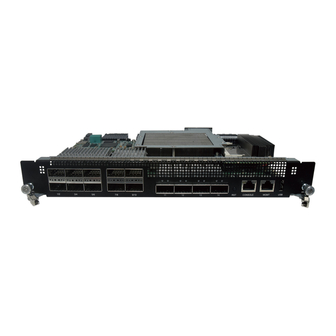
- Page 8 HLM-1101 User Manual The HLM-1101 switch blade provides 14x 100GbE QSFP28 fabric interface. It use Barefoot Tofino T10-032D switch controller. It can be installed into Lanner HTCA-6000 Series network appliances to provide 100 GbE fabric connectivity. Fabric interface switch blade with 14x 100GbE QSFP28 Barefoot Tofino T10-032D 3.2Tbps bandwidth Multilayer Switch...
- Page 9 HLM-1101 User Manual Model HLM-1101 Controller Barefoot Tofino T10-032D switch controller Up to 14x 100GbE Fabric Interface channels, for 6-blade Fabric Interface system 14x 100GbE QSFP28 Ports Front Panel Interface 2x RJ45 Ports for management and console 1x USB 2.0 Port...
- Page 10 HLM-1101 User Manual Description LAN Port 6x 100GbE QSFP28 Ports LAN Port 4x 100GbE QSFP28 Ports LAN Port 4x 100GbE QSFP28 Ports RST Button 1x Reset Button Management Port 1x RJ45 Management Port Console Port 1x RJ45 Console Port USB Port...
- Page 11 HLM-1101 User Manual The block diagram indicates how data flows among components on the motherboard. Please refer to the following figure for your motherboard’s layout design.
- Page 12 HLM-1101 User Manual The motherboard layout shows the connectors and jumpers on the board. Refer to the following picture as a reference of the pin assignments and the internal connectors. CON3 CON3: IEEE1588 Timing Card connector Description Description Description Description...
- Page 13 HLM-1101 User Manual FC5_RN3 25M_CLKN MGT_TP0 TS_GP1_SYNC MGT_TN0 IP_GPIO3_SYNC MGT_RP0 MGT_RN0 156_CLKP 156_CLKN IP_GPIO1_4K IP_GPIO2_1PPS Module_Reset# DPLL_CLK2 UART_TX DPLL_CLK1 UART_RX BSC_SDAT P1: Power Connector (Press-fit) Description Description +12V +12V +12V +12V +12V +12V +12V +12V...
- Page 14 HLM-1101 User Manual To access some components and perform certain service procedures, you must perform the following procedures first. Warning: To reduce the risk of personal injury, electric shock, or damage to the equipment, remove the power cord to remove power from the server. The front panel Power ON/Standby button does not completely shut off system power.
-
Page 15: Files Required
HLM-1101 User Manual Files Required: Install ONIE binary and boot Image: ONIE boot ISO image ONIE installation binary ONIE version: 2021.05-rc1 Make bootable ONIE USB from ISO Copy bootable ONIE ISO (onie-recovery-x86_64-lanner_hmb_1100-r0.iso) into USB(/dev/sdb) dd if=onie-recovery-x86_64-lanner_hmb_1000-r0.iso of=/dev/sdb Make ONIE installation binary... - Page 16 HLM-1101 User Manual BIOS Boot with ONIE USB GRUB select Embed ONIE Install ONIE to HD 1. Clear storage device (SDA) partition table inside HLM-1101 Switch Blade.
- Page 17 HLM-1101 User Manual 2. Change USB stick (sdb) to install stick. Note: The last 4 lines of installation error can be ignored since we do not have an I2C device.
- Page 18 HLM-1101 User Manual 4. Reboot switch blade after complete. 5. After reboot, in GRUB menu choose Install OS to install any Open Network Linux under ONIE environment.
- Page 19 Ubuntu Image: Download Ubuntu server 20.04.3 from Ubuntu official website Intel Software Development Environment (SDE): Download from Intel website Lanner Board Support Platform (BSP) for HLM-1101: Obtain from Lanner support team Make bootable Ubuntu installation USB from ISO Use Rufus to make installation USB Modify Ubuntu default installation method to console serial 1.
- Page 20 HLM-1101 User Manual 2. Under "Install Ubuntu Server" menuentry Replace “quiet” to “console=ttyS0,115200n8” 3. Save the file and remove USB thumb drive from computer. Hardware Setup 1. Plugin console port on the switch 2. Plugin USB drive on the switch 3.
- Page 21 HLM-1101 User Manual BIOS Boot with USB drive 1. Ubuntu installation will start automatically after 5 sec of blank screen 2. After 5 sec. Ubuntu installation process starts 3. Choose basic mode for serial installation wizard...
- Page 22 -c network –businfo enp2s0 – Network interface on front panel of the HLM-1101 switch enp3s0 – Network interface connects to compute blade on the back of the HLM-1101 switch. Below is the compute blade view on network interface. In this example, enp134s0 connects directly to HLM-1101 switch enp3s0.
- Page 23 To fully operate Tofino switch, ASIC will require Intel Software Development Environment (SDE) installed on the operating system. 1. Download from Intel website. 2. After downloading and installing SDE, please request Lanner to provide Board Support Platform (BSP) for HLM-1101 with installation instructions.
- Page 24 HLM-1101 User Manual The two LED on the left side are Link LED; The downward triangle is for Port 2, the upward triangle is for Port 1; After SDK is loaded, and when no Transceiver is plugged in, the LED light turn OFF. After the transceiver is plugged in and Linked, the LED light will steady ON with green LED color.
- Page 25 HLM-1101 User Manual The Port Map below is based on Ubuntu and Cent OS using HMB-6110 computing blade. HLM-1101 Layer 1 PCI Bus Switch Side Ethernet Name Compute Board 0000:3b:00.1 Port 15 enp59s0f1 Layer 1 HMB-6110 0000:af:00.1 Port 16 enp175s0f1 0000:3b:00.1...
- Page 26 HLM-1101 User Manual 1. All products are under warranty against defects in materials and workmanship for a period of one year from the date of purchase. 2. The buyer will bear the return freight charges for goods returned for repair within the warranty period;...
- Page 27 HLM-1101 User Manual When requesting RMA service, please fill out the following form. Without this form enclosed, your RMA cannot be processed.
Need help?
Do you have a question about the HLM-1101 and is the answer not in the manual?
Questions and answers