Table of Contents
Advertisement
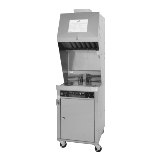
Operations and Service Manual
Models CF 400/500 and CF 400/500-VH
Chester Fried A Division of Giles Enterprises, Inc.
P.O. Box 210247 • 2750 Gunter Park Drive West • Montgomery, AL 36121- 0247 USA • (334) 272- 3528
SERVICE HOTLINE 1-800-288-1555 (USA and Canada only) • FAX (334) 272-3561 • www.chesterfried.com
Form No. 60202 (5/98)
Advertisement
Table of Contents

Related Manuals for GILES Chester Fried CF 400


Summary of Contents for GILES Chester Fried CF 400
- Page 1 Operations and Service Manual Models CF 400/500 and CF 400/500-VH Chester Fried A Division of Giles Enterprises, Inc. P.O. Box 210247 • 2750 Gunter Park Drive West • Montgomery, AL 36121- 0247 USA • (334) 272- 3528 SERVICE HOTLINE 1-800-288-1555 (USA and Canada only) • FAX (334) 272-3561 • www.chesterfried.com...
- Page 2 Safety Precautions FOR YOUR SAFETY DO NOT store or use gasoline or other flammable vapors and liquids in the vicinity of this or any other appliance! Warning!! Improper installation, adjustment, alteration, service or maintenance can cause property damage, injury or death. Read the installation, operating, and maintenance instructions thoroughly before installing or servicing this equipment.
-
Page 3: Table Of Contents
Table of Contents Introduction ........................Installation . - Page 4 Table of Contents Cooking Instructions ......................Marinating Process .
-
Page 5: I Introduction
Introduction Introduction Congratulations on the purchase of your new Chester Fried Electric Fryer. The Chester Fried Models CF 400, 400 VH, 500 and 500 VH fryers are equipped with a high quality cooking computer which is covered by a two year warranty. This new “User friendly” easily programmable cooking computer incorporates extensive design detail by its manufacture WATLOW, and extensive cooking application by the “Chester Fried”... -
Page 6: Installation Instructions
Installation Instructions 1 - 1 Installation Instructions This section provides a summary of the procedures necessary for proper installation of your new Chester Fried Electric Fryer. To prevent personal injury or equipment damage, please ensure the following steps are taken: 1. -
Page 7: Removal Of Fryer From Crate
Installation Instructions IMPORTANT NOTE The exhaust fan in your ventless hood should be lubricated at least every six (6) months. Call Technical Services at 1-800-288-1555 for instructions. DO NOT Modify, Alter or Add Attachments to This Equipment! The previous steps will help to ensure safe and proper installation of your fryer. If you have any questions concerning these procedures, contact your local Chester Fried distributor or other qualified service per- son. -
Page 8: Electrical Requirements
Installation Instructions 1 - 4 Electrical Requirements WARNING Fryers must be adequately and properly grounded. Improper grounding may result in electrical shock. Always refer to your local electrical code to ensure proper grounding of this or any other electrical equipment. Always consult with an electrician or other quali- fied service person to ensure breakers and wiring are of sufficient rating and gauge for the equipment being operated. -
Page 9: Operating Instructions
Operating Instructions 2 - 1 Operating Instructions For your safety, please observe the following precautions when operating your Chester Fried Fryer: 1. Ensure the fry kettle is positioned in a secure, safe location with the casters in the locked position. 2. - Page 10 Operating Instructions...
-
Page 11: Fryer Components And Their Functions
Fryer Components and Their Functions Fryer Components and Their Functions Models CF 400/500 and 400/500-VH The following section is designed to introduce you to the controls used in operating this equipment. DO NOT attempt operation of this unit until you have located each control discussed and fully understand their intended function. -
Page 12: Control Panel
Control Panel Components and Their Function 3 - 1 Control Panel Figure 1 ITEM DESCRIPTION FUNCTION Fig. 1 Power Indicator Light The Green Power Light is on whenever the fryer’s Master Power Switch is in the “ON” position. Fig. 1 Heat Indicator Light The Orange Heat Indicator Light will be on when the fryer’s heating elements are operating. -
Page 13: Lower Cabinet Area
Fryer Components and Their Function 3 - 2 Lower Cabinet Area ITEM DESCRIPTION FUNCTION Fig. 2 Filter Pan Hold-Down Bracket The Hold-Down Bracket is contained in the Filter Pan and Latches and serves to ensure the filter paper is held tightly in place by means of the four locking latches. - Page 14 Fryer Components and Their Function ITEM DESCRIPTION FUNCTION Fig. 2 Filter Pan The Filter Pan contains the filter paper which serves to remove breading and other impurities from the oil during the filtering procedure. Oil is drained into the Filter Pan where the fryer’s pumping action draws it through the filter paper and returns it to the cooking vessel by way of the Filter Pan Hose.
- Page 15 Fryer Components and Their Function 3 - 3 Cooking Vessel ITEM DESCRIPTION FUNCTION Fig. 3 Oil Temp Probe The Oil Temp Probe senses oil temperature during fryer operation for temperature control. It’s signal is directed to the fryer’s control unit for comparison with the temperature selected by remote set-pot on the operator control panel.
-
Page 16: Cooking Vessel
Fryer Components and Their Function Cooking Vessel Figure 3... - Page 17 Fryer Components and Their Function Air Cleaning Components Shown in their operative positions with Hood Access Panel removed. (VH) models only Figure 4...
- Page 18 Fryer Components and Their Function 3 - 4 Air Cleaning Components. (Use with VH models.) Figure 5 ITEMS DESCRIPTION FUNCTION Fig. 4 & 5 Charcoal Filter Replaced The Charcoal Filter helps to remove odor generated at least MONTHLY during cooking. This comprises the third and final stage of the air filtration system used in the Ventless Hood System.
-
Page 19: Cooking Computer Features
Fryer Components and Their Function 3 - 4 Cooking Computer Features To help you understand the many programming features of the cooking computer, we strongly suggest you read the following: MELT CYCLE This melt cycle is shipped to you OFF and must be turned ON for those fryer users who occasionally or regularly use SOLID SHORTENING. - Page 20 Fryer Components and Their Function STIR CYCLE AND ALARM Your fryer is equipped with a stir message and a repeating one second on / one second off sound alarm telling you it’s time to stir your product. This feature is a Chester Fried preset time of 62% of each of the 8 menu times previously set to prevent the chicken from sticking to itself.
-
Page 21: Cooking Computer Programming
Fryer Components and Their Function 3. Boil Cycle Key (For use with boil out procedure portion of this manual only!) The boil cycle feature is used for cleaning the fryer by using fryer heated cold water & Chester Clean (part #71425). When the Boil key is pressed and held for 5 seconds, and no menu is active (00:00), the red boil light will come on and the display will alternately flash boil and 00:00 This activates a fixed temperature setting of 200°F (93°C). - Page 22 How to Program Menu Temperatures & Times on Menu Keys 1 thru 8 1. Press power rocker switch to on. (Green indicator light comes on) 2. Press & keys simultaneously for (6) seconds until SP 1 flashes alternately with the preset menu temperature. 3.
-
Page 23: Testing The Fryer
Testing the Fryer We at Chester Fried take pride in the quality of our workmanship. Every effort has been made to ensure your unit is in good operating condition when you receive it. Each unit must pass a rigorous quality control test prior to shipment. -
Page 24: Operational Check-Out Of The Filter Pump
Testing the Fryer 3. The wet element should dry within 15 seconds after fryer element shut-off signifying heat. 4. If the elements do not appear operational, refer to the troubleshooting guide. 5. If the heating elements are operational, clean the fryer as described under instructions for the boil-out procedure described in this manual. -
Page 25: Preparing The Fryer For Operation
Preparing the Fryer for Operation Your new fryer should be cleaned thoroughly before actual cooking takes place. To accomplish this, follow the procedure described in the following Boil-Out Procedure section. 5 - 1 Fryer Boil-Out Procedure This section describes the cleaning process for your fryer known as the “Boil-Out”. A “Boil-Out” should be performed on the new equipment prior to actual cooking and every time shortening is removed from the fryer for cleaning of the fry-kettle and refill with fresh shortening. - Page 26 Preparing the Fryer for Operation 8. Place Pump Switch in the “ON” position and allow shortening to return to the fry-kettle and out through the drain. Use this opportunity to “Wash-Down” breading which has accumulated in the bottom of fry- kettle.
- Page 27 Preparing the Fryer for Operation 9. After “Washing Down” all accumulated breading and crumbs from the bottom of the fry-kettle, place the Pump Switch in the “OFF” position and allow the shortening to drain into the Filter Pan. 10. Turn the T-Handle on the drain valve clockwise to close. 11.
- Page 28 Preparing the Fryer for Operation 22. Ensure the drain valve is closed by turning the T-Handle fully clockwise. 23. Fill the fryer with water to the Oil Level Line. 24. Carefully add Chester Clean to the water following the directions on the container. CAUTION If you choose to use a cleaner other than Chester Clean to “Boil-Out”...
- Page 29 Preparing the Fryer for Operation Filter Pan Shown with Drain Hose Attached Figure 7...
-
Page 30: Cleaning Of Filter Pan/Replacement Of Filter Paper
Preparing the Fryer for Operation 5 - 2 Cleaning of Filter Pan/Replacement of Filter Paper The following steps should be taken with the Filter Pan removed from the fryer. The Filter Pan should be thoroughly cleansed during each “Boil Out” procedure. Do not attempt to clean the Filter Pan when pan is still in fryer cabinet. - Page 31 Preparing the Fryer for Operation Disassembled View of Filter Pan; All Models Figure 9 (photo not available at this time) Hold-down Filter Pan Latch Hold-down Filter Pan Frame Screen IMPORTANT NOTE: DAILY Filter Paper Replacement is Recommended! Instructions for changing the Filter Paper: 1.
- Page 32 Preparing the Fryer for Operation 5 - 3 Cleaning considerations for Chester Fried Ventless Hood System Ventless hoods are designed to remove grease vapors from the cooking operations and re-circulate the cleaned air. The catch and hold principal of the recirculating system means you must perform daily clean- ing of the EAC and baffle filter.
-
Page 33: Removal And Replacement Of Filters
Preparing the Fryer for Operation Re-install both parts at the beginning of each day. 8. CHANGE SOAK TANK SOLUTION AT LEAST MONTHLY by dipping it out and into the sink. NEVER LIFT THE SOAK TANK TO EMPTY. 9. Clean the Baffle Filter DAILY by simply spraying and rinsing residue from the filter with HOT water and letting it dry. - Page 34 Preparing the Fryer for Operation Upper Hood Area Showing Location of Components Figure 8 Air Cleaning Components Figure 10 Charcoal Filter Baffle Filter Electronic Filter...
-
Page 35: Operating The Fryer's Controls For Cooking
Preparing the Fryer for Operation 5 - 5 Operating the Fryer’s Controls for Cooking Before cooking with the fryer, ensure you have read and fully understand the intended functions of each control used on the fryer. Detailed explanations are found in Section 3 of this manual. 1. -
Page 36: Filtering The Fryer
Preparing the Fryer for Operation 5 - 6 Filtering the Fryer The fryer should be filtered after every 4th load. 1. Use thermal oven mitts during this procedure to prevent burns from hot oil and metal surfaces of the fryer. 2. -
Page 37: Inspection And Testing Of Safety Interlocks
Preparing the Fryer for Operation 5 - 7 Inspection and Testing of Safety Interlocks (VH Series Only) Your Chester Fried Ventless Hood System incorporates an interlock system to ensure the unit is operated in a safe and effective manner. Testing of the interlock system should be conducted monthly in the follow- ing manner. - Page 38 Preparing the Fryer for Operation Initial/ Initial/ Check Date Check Date Grease Baffle Collector Cell Charcoal Filter Blocked Filter Fusible Links Clean Plenum and Blower Fire System Inspection The proper procedure for inspecting the interlock systems and performing routine cleaning is located in section 2-4 of this manual. •Semi-annual inspection should be performed by a qualified fire equipment company.
- Page 39 Preparing the Fryer for Operation Figure 11 VH Series...
-
Page 40: Fire Suppression System
Fire Suppression System 6 - 1 System Description The fire suppression system used in your Giles Ventless Hood Fryer is an Ansul R-102 Restaurant Fire Suppression System (Standard UL 197 Listed). Final installation, charging and testing of the system is to be performed by an authorized Ansul distributor in accordance with the systems listing. -
Page 41: Maintenance
Ensure the pull station is clearly marked and easily accessible. Check with the authority having jurisdiction for the requirements in your area. See Giles Design Installation Recharge and Maintenance Manual for R-102 Restaurant Fire Suppression System for complete installation instructions. -
Page 42: Service
Fire Suppression System is to be accomplished semi-annually by qualified fire equipment service personnel. Such maintenance shall consist of the following (Consult the Giles Enterprises Design Installation, Recharge and Maintenance Manual for complete servicing guide- lines). - Page 43 Fire Suppression System Upper Rear Panel Removed Showing Location of Fire Suppression System Figure 12...
- Page 44 Fire Suppression System 6 - 6 Fire Suppression Illustrations Assembly, Fire Suppression Plumbing Assembly, Fusible Link Conduit Assembly, Manual Pull Conduit Assembly, Fire Suppression Conduit...
- Page 45 Fire Suppression System 6 - 6 Assembly, Fire Suppression Plumbing Item No. Part No. Description No. Req’d Remarks 34843 Assy., Elec Comp (Stage 2) 40129 Assy., 1.5 Gal Tank w/ Adapter 11575 Screw, 10-32 x Truss SS 11975 Washer, Flat #10 12050 Washer, Lock #10 11925...
-
Page 46: Illustrations
Fire Suppression System 6 - 6 Illustrations Fire Suppression Plumbing Diagram... - Page 47 Fire Suppression System 6 - 6 Assembly, Fusible Link Conduit Item No. Part No. Description No. Req’d Remarks 40133 Detector, Terminal 40130 Assy., Hood Seal Adapter 30898 Conduit, 46375 Elbow, 90° Pulley 34924 Conduit, x 28 34923 Conduit, x 18 34922 Conduit, x 10...
- Page 48 Fire Suppression System 6 - 6 Illustrations Fusible Link Conduit Diagram...
- Page 49 Fire Suppression System 6 - 6 Assembly, Manual Pull Conduit Item No. Part No. Description No. Req’d Remarks 41905 Coupling, " NPS Rigid 1 22800 Coupling, Reducing 24220 Connector 30227-6 Conduit, x 28 46025 Pulley, Corner/Set Screw 30895 Conduit, 46400 Pulley, Pipe (T) 30898 Conduit,...
- Page 50 Fire Suppression System 6 - 6 Illustrations Manual Pull Conduit Diagram...
- Page 51 Fire Suppression System 6 - 6 Assembly, Fire Suppression Conduit Item No. Part No. Description No. Req’d Remarks 34865 Assy., Fire Suppress Plumbing 34806 Assy., Fusible Link Conduit 30227-6 Assy., Manual Pull Conduit 40132 OEM Release/Bracket Assy 46300 Remote Manual Pull Station 30175 Shield, Manual Pull 10800...
- Page 52 Fire Suppression System 6 - 6 Illustrations Fire Suppression Conduit Diagram...
-
Page 53: Cooking Instructions
Cooking Instructions 7 - 1 Marinating Process Marinating is the process by which salt and special spices are absorbed into the tissue to enhance the fla- vor of the chicken. This procedure is one of the primary factors that accounts for Chester Fried’s remark- able taste appeal. -
Page 54: Breading
Cooking Instructions 7 - 3 Breading Breading is the final step before frying . Chester Fried Breadings have been blended according to strict standards and are formulated for great taste. 1. Lightly dust the chicken in the breading mix. 2. Place the chicken back in the Batter Dip Seasoning. Totally immerse the pieces in the Batter Dip two times coating the chicken with this solution. -
Page 55: Loading The Chicken
Cooking Instructions 7 - 4 Loading the Chicken The weight of the chicken will determine the quantity the cooker can accept and the specific cook time. If each bird weighs 2 ⁄ lb. (1.2k). (See chart for product amount). Piece CF-400 CF-500 Thighs... -
Page 56: Stirring The Chicken
Cooking Instructions 7 - 5 Using IQF and Pre-Marinated Chicken Good results can be obtained using a marinated IQF or a “pre-marinated” chicken product rather than fresh chicken. Use of a “pre-marinated” product eliminates the need for marinating at the store level. The IQF product should be thawed and processed in the same fashion as fresh chicken. - Page 57 Cooking Instructions 4. Lightly Dust the potato wedges in the Breading Mix. 5. Place the wedges in the Batter Dip Seasoning Mix. Totally immerse them in the Batter Dip two times. 6. Thoroughly coat the wedges with the Breading a second time and place on Staging Tray. 7.
-
Page 58: Troubleshooting
Troubleshooting 8 - 1 Temperature Control System with Cooking Computer Probable Cause Repair Procedure Problem FRYER WILL NOT TURN ON: A. Not connected to power source. A. Connect to proper power source. No power light. B. Bad fuse or circuit breaker. B. - Page 59 Troubleshooting 8 - 1 Temperature Control System with Cooking Computer Probable Cause Repair Procedure Problem FRYER HEAT SLOW: A. Incorrect cooking procedures. A. Consult operations manual for (slow recovery) Heat light stays on. proper cooking procedure. B. Element failing. B. Replace bad element. C.
-
Page 60: Automatic Basket Lift And Oil Filtration System
Troubleshooting 8 - 2 Automatic Basket Lift and Oil Filtration System Probable Cause Repair Procedure Problem BASKET WILL NOT GO UP OR A. Power not on. A. Turn Power Switch to on position. DOWN: Elevator motor not on. B. Selector Switch not in cook B. - Page 61 Parts List 9 - 1 Front Control Panel - VH Fryer Item No. Part No. Description No. Req’d Remarks 21190 Power Switch 21189 Selector Switch 24241 Cooking Computer 24209 On/Check/Wash Light 22275 Power/Heat/High-Limit Light...
- Page 62 Parts List 9 - 2 Rear View of Lower Cabinet Item No. Part No. Description No. Req’d Remarks 32158 Elevator Motor 23175 Micro Switch 73225 Filter Pan(Complete Assemble) MGF 40 73153 Filter Pan(Complete Assemble) MGF 50 30028-8 Micro Switch Bracket...
- Page 63 Parts List 9 - 3 Rear View of Header Section Item No. Part No. Description No. Req’d Remarks 21950 Fuse Holder 21900 Fuse, 15 AMP SC-15 30186 Transformer 23754 Safety Board 425°F (218°C) 23751 Terminal Block 32123 Contactor MGF-40 1PH 50A 32113 Contactor MGF-40 3PH 40A 32193...
- Page 64 Parts List 9 - 4 Rear View of Upper Hood Section (VH Models Only) Item No. Part No. Description No. Req’d Remarks 21825 24237 Switch, Plunger 23001 Vacuum Switch 23751 Terminal Block 23782 Sonalert Clogged Filter 22950 Sonalert LED Driver (Part of HV Supply) 23776 Air Filter Module 24208...
- Page 65 Parts List 9 - 5 Filter Pan Assembly Item No. Part No. Description No. Req’d Remarks 43302 Hose Assembly for CF-400 43301 Hose Assembly for CF-500 (Not Shown) 44150 ⁄ ” (1.27cm) Brass Assembly/Male Quick Disconnect 42250 90° (1.27cm) Street Ell 73149 Hold Down Frame 54526...
-
Page 66: Wiring Diagrams
Wiring Model CF-400/500 / CF-400G/500 VH Wiring Diagrams Wiring Diagram CF-400/500 (1 phase) Wiring Diagram CF-400/500 (3 phase) Wiring Diagram CF-400 VH (1 phase) Wiring Diagram CF-400 VH (3 phase) Wiring Diagram CF-500 VH (1 phase) Wiring Diagram CF-500 VH (3 phase) Wiring Schematic CF-400/500 (1 &... - Page 67 Wiring Model CF-400/500 (1 phase) 10 - 1 Item No. Part No. Description No. Req’d Remarks 30186 Transformer Assembly 32158 Motor, Elevator 25275 Wire Nut (Blue) 23754 Safety Board, 425°F (218°C) 24241 Computer Controller (Watlow) 24212 Sensor, Variable 24213 Sensor, Safety-CF400 21177 Sensor, Safety-CF500 25250...
- Page 68 Wiring Model CF-400/500 (1 phase) 10 - 2 Wiring Diagram...
- Page 69 Wiring Model CF-400/500 (3 phase) 10 - 3 Item No. Part No. Description No. Req’d Remarks 30186 Transformer Assembly 32158 Motor, Elevator 25275 Wire Nut (Blue) 23754 Safety Board, 425°F (218°C) 24241 Computer Controller (Watlow) 24212 Sensor, Variable 24213 Sensor, Safety CF-400 21177 Sensor, Safety-CF-500 25250...
- Page 70 Wiring Model CF-400/500 (3 phase) 10 - 4 Wiring Diagram...
- Page 71 Wiring Model CF-400 VH (1 phase) 10 - 5 Item No. Part No. Description No. Req’d Remarks 21125 Contact Board 24208 Power Pack w/ Driver Board 21825 Fan Motor 23200 Switch, Hood Interlock 23241 Computer Controller (Watlow) 24212 Sensor, Variable 24213 Sensor, Safety 24237...
- Page 72 Wiring Model CF-400 VH (1 phase) 10 - 6 Wiring Diagram...
- Page 73 Wiring Model CF-400 VH (3 phase) 10 - 7 Item No. Part No. Description No. Req’d Remarks 21125 Contact Board 24208 Power Pack w/ Driver Board 21825 Fan Motor 23200 Switch, Hood Interlock 23241 Computer Controller (Watlow) 24212 Sensor, Variable 24213 Sensor, Safety 24237...
- Page 74 Wiring Model CF-400 VH (3 phase) 10 - 8 Wiring Diagram...
- Page 75 Wiring Model CF-500 VH (1 phase) 10 - 9 Item No. Part No. Description No. Req’d Remarks 21125 Contact Board 24208 Power Pack w/ Driver Board 21825 Fan Motor 23200 Switch, Hood Interlock 23241 Computer Controller (Watlow) 24212 Sensor, Variable 21177 Sensor, Safety 24237...
- Page 76 Wiring Model CF-500 VH (1 phase) 10 - 10 Wiring Diagram...
- Page 77 Wiring Model CF-500 VH (3 phase) 10 - 11 Item No. Part No. Description No. Req’d Remarks 21125 Contact Board 24208 Power Pack w/ Driver Board 21825 Fan Motor 23200 Switch, Hood Interlock 23241 Computer Controller (Watlow) 24212 Sensor, Variable 21177 Sensor, Safety 24237...
- Page 78 Wiring Model CF-500 VH (3 phase) 10 - 12 Wiring Diagram...
- Page 79 Wiring Model CF-400/500 (1 & 3 Phase) 10 - 13 Wiring Schematic...
Need help?
Do you have a question about the Chester Fried CF 400 and is the answer not in the manual?
Questions and answers
on model cf 500 have an er 12 code..what is it