Table of Contents
Advertisement
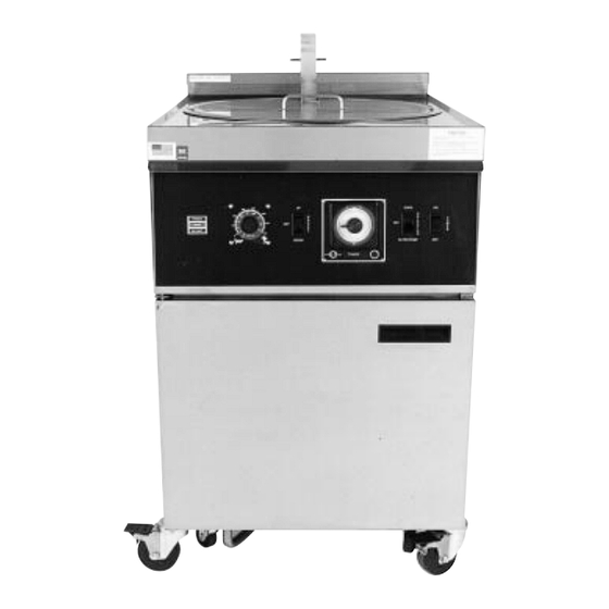
Operations and Service Manual
Model CF-401, CF-560 and CF-720
CF-720
Chester Fried A Division of Giles Enterprises, Inc.
P.O. Box 210247 • 2750 Gunter Park Drive West • Montgomery, AL 36121- 0247 USA • (334) 272-3528
SERVICE HOTLINE 1-800-288-1555 (USA and Canada only) • FAX (334) 272-3561 • www.chesterfried.com
Form No. 64651 (8/98)
CF-401
Advertisement
Table of Contents

Related Manuals for GILES Chester Fried CF-401


Summary of Contents for GILES Chester Fried CF-401
- Page 1 CF-401 CF-720 Chester Fried A Division of Giles Enterprises, Inc. P.O. Box 210247 • 2750 Gunter Park Drive West • Montgomery, AL 36121- 0247 USA • (334) 272-3528 SERVICE HOTLINE 1-800-288-1555 (USA and Canada only) • FAX (334) 272-3561 • www.chesterfried.com...
- Page 2 Safety Precautions For Your Safety Do not store or use gasoline or other flammable vapors and liquids in the vicinity of this or any other appliance! WARNING Improper installation, adjustment, alteration, service or maintenance can cause property damage, injury or death. Read the installation, operating and maintenance instructions thoroughly before installing or servicing this equipment.
-
Page 3: Table Of Contents
Table of Contents Introduction........................1 Installation 1 - 1 Installation Instructions......................2 1 - 2 Removal of Fryer From Crate....................3 1 - 3 Ventilation of Fryers......................3 1 - 4 Electrical Requirements....................... 3 Operating Instructions 2 - 1 Operating Instructions ......................5 Fryer Components and Their Functions 3 - 1 Control Panel ........................ - Page 4 Table of Contents Troubleshooting 7 - 1 Control System with Cooking Computer................36 7 - 2 Automatic Basket Lift and Oil Filtration System............... 37 Parts 8 - 1 Parts List ..........................38 8 - 2 Parts List—Filter Pan Models CF-401 and CF-560 ............40 Wiring 9 - 1 Wiring Diagram Model CF-401 with Electromechanical Timer (3 Phase) ......
-
Page 5: Introduction
Introduction Congratulations on the purchase of your new Chester Fried Electric Fryer. The Chester Fried Models CF- 401, 560 and CF-720 are equipped with a high quality cooking computer which is covered by a two year warranty. This new “user friendly” easily programmable cooking computer incorporates extensive design detail by its manufacturer WATLOW, and extensive cooking application by the “Chester Fried”... -
Page 6: Installation Instructions
Installation Instructions 1 - 1 Installation Instructions This section provides a summary of the procedures necessary for proper installation of your new Chester Fried Electric Fryer. To prevent personal injury or equipment damage, please ensure that the following steps are taken: For your safety do not store or use gasoline or other flammable vapors and liquids in the vicinity of this or any other appliance! Keep the appliance and surrounding area free and clear from combustible materials (minimum 4... -
Page 7: Removal Of Fryer From Crate
Installation Instructions 1 - 2 Removal of Fryer from Crate Your Chester Fried Fryer may arrive enclosed by a wooden crate. If your unit arrived uncrated, go to Sec- tion 1-3. The Fryer is secured to a wooden platform by means of high-tensile strength strapping. Carefully cut and remove the plastic shipping wrap and the strapping mentioned above. -
Page 8: Operating Instructions
Operating Instructions 2 - 1 Operating Instructions For your safety, please observe the following precautions when operating your Chester Fried Fryer. Ensure the fry kettle is positioned in a secure safe location with the casters in the locked position. Consult an electrician to ensure all electrical specifications have been met and the unit is properly grounded. -
Page 9: Fryer Components And Their Functions
Fryer Components and Their Functions Fryer Components and Their Functions The following section is designed to introduce you to the controls used in operating this equipment. DO NOT attempt operation of this unit until you have located each control discussed and fully understand their function. - Page 10 Fryer Components and Their Functions Figure 1...
-
Page 11: Electro-Mechanical Timer Control Panel
Fryer Components and Their Functions Figure 2 Electro-Mechanical Timer Control Panel... - Page 12 Fryer Components and Their Functions 3 - 2 Electro-Mechanical Timer Control Panel Components and Their Functions ITEM DESCRIPTION FUNCTION Fig. 2 Power Switch The Power Switch is a two-position switch. Move the switch upward to the “ON” position for operation. Fig.
- Page 13 Fryer Components and Their Functions Figure 3 Lower Cabinet Area...
- Page 14 Fryer Components and Their Functions 3 - 3 Lower Cabinet Area Components and Their Functions ITEM DESCRIPTION FUNCTION Fig. 3 Hold-Down Bracket (Not Shown) The Hold-Down Bracket is contained in the filter pan and serves to ensure the filter paper is held tightly in place by means of the four locking latches.
- Page 15 Fryer Components and Their Functions Figure 4 Cooking Vessel...
-
Page 16: Cooking Vessel
Fryer Components and Their Functions 3 - 4 Cooking Vessel ITEM DESCRIPTION FUNCTION Fig. 4 Oil Temp Probe The Oil Temp Probe senses oil temperature during fryer operation for temperature control. Its signal is directed to the fryer’s control unit for comparison with the temperature selected by remote set-pot on the operator. - Page 17 Fryer Components and Their Functions Figure 5 Electronic Controller...
-
Page 18: Cooking Computer Features
Fryer Components and Their Functions 3 - 5 Cooking Computer Features To help you understand the many programming features of the cooking computer, we strongly suggest you read the following: Cool Down Cycle After any of your 8 menu time cycles end (00:00) and your fryer is not required for use for an hour or more, you can reduce energy cost by pressing the “COOL”... - Page 19 Fryer Components and Their Functions Fryer Components and Their Functions Figure 6 Program Menu...
-
Page 20: Computer Key Functions
Fryer Components and Their Functions Fryer Components and Their Functions 3 - 6 Computer Key Functions The following is a description of the basic function and operation of your cooking computer’s key pad. Basket Key When the basket key is pressed once, the up and down arrow keys blink. If the basket is up, it can only be lowered using the down arrow ( ) key. -
Page 21: Cooking Computer Programmer
Fryer Components and Their Functions 3 - 7 Cooking Computer Programmer The first step is to determine the time and temperature for each product. The recommended temperatures for fried chicken are 335° F (168° C). Channel 1 is the only menu key programmed for 335° F (168° C) and 10:30 minutes when you receive your fryer. - Page 22 Fryer Components and Their Functions Figure 8 Front Panel Mechanical Timer...
-
Page 23: Mechanical Timer Operating Instructions
Fryer Components and Their Functions 3 - 8 Mechanical Timer Operating Instructions Turn power switch on. Make sure selector switch is in “COOK” position. Set temperature dial (thermostat) to desired cooking temperature (335° F/168° C). “HEAT” light will come on until oil has reached set temperature. When the heat light goes out, lower the basket by pressing the down arrow ( ) on the basket “up/down”... -
Page 24: Testing The Fryer
Testing the Fryer Testing the Fryer We at Chester Fried take pride in the quality of our workmanship. Every effort has been made to ensure that your unit is in good operating condition when you receive it. Each unit must pass a rigorous quality control test prior to shipment. -
Page 25: Operational Check-Out Of Filter Pump
Testing the Fryer Testing the Fryer If the elements are not operational, refer to the troubleshooting guide in section 7. If the heating elements are operational, clean the fryer as described under the instructions for the boil-out procedure described in Section 5-1. After thorough cleaning, fill fry pot to proper level with shortening. - Page 26 Testing the Fryer Figure 9 Lower Cabinet...
-
Page 27: Preparing The Fryer For Operation
Preparing the Fryer for Operation Preparing the Fryer for Operation Your new fryer should be cleaned thoroughly before actual cooking takes place. To accomplish this, follow the procedure described in the following Boil-Out Procedure Section. 5 - 1 Fryer Boil-Out Procedure This section describes the cleaning process for your fryer known as the “Boil-Out.”... - Page 28 Preparing the Fryer for Operation Ensure the diverter valve is positioned so its handle points upward. Place Selector switch in the “Filter” position and allow shortening to return to the fry-kettle and out through the drain. Use this opportunity to “Wash-Down” breading which has accumulated in the bottom of the fry-kettle.
- Page 29 Preparing the Fryer for Operation Figure 10 Filter Pan without Drain Hose...
- Page 30 Preparing the Fryer for Operation Disconnect the drain hose from the fryer at the quick disconnect fitting beside the diverter valve. Always hold both ends of the drain hose in an upright position to avoid spillage of residual oil which may be trapped in the hose.
-
Page 31: Cleaning Of Filter Pan/Replacement Of Filter Pan
Preparing the Fryer for Operation Mop out excess water from the fryer pot with a dry cloth. Close the drain valve again. Replace filter pan after thorough cleaning. IMPORTANT NOTE Do Not pump “Boil-Out” thru filter pump. Doing so can damage pump and void warranty. Fill fryer with shortening to the proper level. - Page 32 Preparing the Fryer for Operation Figure 11 Disassembled View of Filter Pan; All Models Instructions for changing the Filter Paper: Remove the crumb and breading residue which surrounds the Hold-Down rack that secures the filter paper in place. Remove crumbs and breading residue from the top sheet of filter paper with the metal crumb shovel supplied with the fryer.
-
Page 33: Operating Fryer Controls For Cooking
Preparing the Fryer for Operation 5 - 3 Operating the Fryer’s Controls for Cooking Before cooking with the fryer, ensure that you have read and fully understand the intended functions of each control used on the fryer. Detailed explanations are found in Section 3 of this manual. Fill fryer with shortening approximately ⁄... - Page 34 Preparing the Fryer for Operation Ensure filter paper (2 pieces) is properly positioned in the filter pan as described in Section 5 under the section detailing replacement of the filter paper. Place the selector switch in the “OFF” position. WARNING Failure to ensure the selector switch is in the “OFF”...
-
Page 35: Cooking Instructions
Cooking Instructions 6 - 1 Marinating Process Marinating is the process by which salt and special spices are absorbed into the tissue to enhance the fla- vor of the chicken. This procedure is one of the primary factors that accounts for Chester Fried’s remark- able taste appeal. -
Page 36: Breading
Cooking Instructions 6 - 3 Breading Breading is the final step before frying . Chester Fried Breadings have been blended according to strict stan- dards and are formulated for great taste. Lightly dust the chicken in the breading mix. Place the chicken back in the Batter Dip Seasoning. Totally immerse the pieces in the Batter Dip two times coating the chicken with this solution. -
Page 37: Loading The Chicken
Cooking Instructions 6 - 4 Loading the Chicken The weight of the chicken will determine the quantity the cooker can accept and the specific cook time. The approximate weight of each bird is 2 lb. (1.2k). (See chart for product amount) Piece MGF-20 MGF-40... -
Page 38: Preparing The Potatoes
Cooking Instructions 6 - 7 Preparing the Potatoes The preparation for the potatoes plays a vital role in the success of your Chester Fried operation. We sug- gest that you use a white Idaho potato, 80 count in size. The Idaho potato comes out of the fry-kettle as light and golden in color as your fried chicken. - Page 39 Troubleshooting 7 -1 Temperature Control System with Cooking Computer; All Models Problem Probable Cause Repair Procedure FRYER WILL NOT TURN ON: A. Not connected to power source. A. Connect to proper power source. No power light. B. Bad fuse or circuit breaker. B.
- Page 40 C. Solid shortening allowed to sit in pump. C. Disassemble and re-oil pump and clean out plumbing. If you require repair or assistance, please contact your local Giles representative. If you require further assistance please contact our corporate office in Montgomery, Alabama at 1-800-288-1555.
- Page 41 Parts 8 - 1 Parts List Item No. Part No. Description No. Req’d Remarks 21151 21151 Contactor 3 ph 63 amp 23751 23751 Terminal Block 21175 21175 Contactor 208/240 50 amp 21166 21166 Circuit Breaker 208/240 21950 21950 Fuseholder 21900 21900 Fuse 15 amp 21190...
- Page 42 Parts Controller Pump & Elevator Assembly...
- Page 43 Parts Parts 8 - 2 Parts List Filter Pan Model CF-720, CF-560, CF-401 Item No. Part No. Description Remarks 34701 34701 Filter Pan Assy Fits 401, 560, 720 Entire Assy 33004 Filter Pan Fits 401, 560, 720 33008 Hold Down Frame 54526 Hold Down Lever 30040-4...
- Page 44 Wiring 9 - 1 Model CF-401 with Electromechanical Timer (3 Phase) 9 - 2 Model CF-401 with Electromechanical Timer (1 Phase) 9 - 3 Model CF-401 with Cooking Computer (3 Phase) 9 - 4 Model CF-401 with Cooking Computer (1 Phase) 9 - 5 Model CF-560 with Electromechanical Timer (3 Phase) 9 - 6...
- Page 45 Wiring 9 - 1 Model CF-401 with Electromechanical Timer (3 Phase) Item No. Part No. Description No. Req’d Remarks 32143 Contactor Assembly 63AMP 21950 21950 Fuseholder W/15A Fuse (21900) 21190 21190 Power Switch 22875 Set Pot 24000 Variable Thermostat 240V 24001 Variable Thermostat 208V 23754...
- Page 46 Wiring 9 - 1 Wiring Diagram...
- Page 47 Wiring 9 - 2 Model CF-401 with Electromechanical Timer 208/240V (1 Phase) Item No. Part No. Description No. Req’d Remarks 32193 32193 Contactor Assembly 75 AMP 1 Phase 21950 21950 Fuseholder W/15A Fuse (21900) 21190 21190 Power Switch 22875 Set Pot 24000 Variable Thermostat 240V 24001...
- Page 48 Wiring 9 - 2 Wiring Diagram...
- Page 49 Wiring 9 - 3 Model CF-401 with Cooking Computer 208/240V (3 Phase) Item No. Part No. Description No. Req’d Remarks 32143 Contactor Assembly 63AMP (1 phase) 21950 21950 Fuseholder W/15A Fuse (21900) 21190 21190 Power Switch 30186 Transformer 23754 23754 Safety Thermostat 23751 23751...
- Page 50 Wiring 9 - 3 Wiring Diagram...
- Page 51 Wiring 9 - 4 Model CF-401 with Cooking Computer208/240V (1 Phase) Item No. Part No. Description No. Req’d Remarks 32193 32193 Contactor Assembly 75AMP 2 Pole (1 phase) 21950 21950 Fuseholder W/15A Fuse (21900) 21190 21190 Power Switch 30186 Transformer 23754 23754 Safety Thermostat...
- Page 52 Wiring 9 - 4 Wiring Diagram...
- Page 53 Wiring 9 - 5 Model CF-560 with Electromechanical Timer 208/240V (3 Phase) Item No. Part No. Description No. Req’d Remarks 32143 Contactor Assembly 63AMP 21950 21950 Fuseholder W/15A Fuse (21900) 21190 21190 Power Switch 22875 Set Pot 24000 Variable Thermostat 240V 24001 Variable Thermostat 208V 23754...
- Page 54 Wiring Wiring 9 - 5 Wiring Diagram...
- Page 55 Wiring 9 - 6 Model CF-560 with Electromechanical Timer 208/240V (1 Phase) Item No. Part No. Description No. Req’d Remarks 32193 32193 Contactor Assembly 75AMP (I Phase) 21950 21950 Fuseholder W/15A Fuse (21900) 21190 21190 Power Switch 22875 Set Pot 24000 Variable Thermostat 240V 24001...
- Page 56 Wiring Wiring 9 - 6 Wiring Diagram...
- Page 57 Wiring 9 - 7 Model CF-560 with Cooking Computer 208/240V (3 Phase) Item No. Part No. Description No. Req’d Remarks 32143 Contactor Assembly 63AMP 3 Pole 21950 21950 Fuseholder W/15A Fuse (21900) 21190 21190 Power Switch 30186 Transformer 23754 23754 Safety Thermostat 23751 23751...
- Page 58 Wiring 9 - 7 Wiring Diagram...
- Page 59 Wiring 9 - 8 Model CF-560 with Cooking Computer 208/240V (1 Phase) Item No. Part No. Description No. Req’d Remarks 32143 Contactor Assembly 75AMP 2 Pole 21950 21950 Fuseholder W/15A Fuse (21900) 21190 21190 Power Switch 30186 Transformer 23754 23754 Safety Thermostat 23751 23751...
- Page 60 Wiring 9 - 8 Wiring Diagram...
- Page 61 Wiring 9 - 9 Model CF-720 with Cooking Computer 208/240V (3 Phase) Item No. Part No. Description No. Req’d Remarks 32143 Contactor Assembly 63 MP 3 Pole 21950 21950 Fuseholder W/15A Fuse (21900) 21190 21190 Power Switch 30186 Transformer 23754 23754 Safety Thermostat 23751...
- Page 62 Wiring Wiring 9 - 9 Wiring Diagram...
- Page 63 Wiring 9 - 10 Model CF-720 with Cooking Computer 480V (3 Phase) Item No. Part No. Description No. Req’d Remarks 32143 Contactor Assembly 63AMP 21950 21950 Fuseholder W/15A Fuse (21900) 21190 21190 Power Switch 30186 Transformer 23754 23754 Safety Thermostat 23751 23751 Terminal Block...
- Page 64 Wiring 9 - 10 Wiring Diagram...
- Page 65 Wiring 9 - 11 Model CF-720 with Electromechanical Timer 208/240V (3 Phase) Item No. Part No. Description No. Req’d Remarks 32143 Contactor Assembly 63AMP 32123 Contactor Assembly 50AMP 20513 20513 Circuit Breaker 21950 21950 Fuseholder W/15A Fuse (21900) 21190 21190 Power Switch 22875 Set Pot...
- Page 66 Wiring 9 - 11 Wiring Diagram...
- Page 67 Wiring 9 - 12 Model CF-720 with Electromechanical Timer 480V (3 Phase) Item No. Part No. Description No. Req’d Remarks 32143 Contactor Assembly 63AMP 21950 21950 Fuseholder W/15A Fuse (21900) 21190 21190 Power Switch 22875 Set Pot 24000 Variable Thermostat 23754 23754 Safety Thermostat...
- Page 68 Wiring 9 - 12 Wiring Diagram...
- Page 69 Wiring 9 - 13 Model CF-720 with Electromechanical Timer 220/380V (3 Phase) Item No. Part No. Description No. Req’d Remarks 33992 Contactor Assembly 220/380V 21900 21900 Fuseholder W/15A Fuse (21900) 21190 21190 Power Switch 22875 Set Pot 24000 Variable Thermostat 23754 23754 Safety Thermostat...
- Page 70 Wiring 9 - 13 Wiring Diagram...
Need help?
Do you have a question about the Chester Fried CF-401 and is the answer not in the manual?
Questions and answers