Table of Contents
Advertisement
Advertisement
Table of Contents

Subscribe to Our Youtube Channel
Related Manuals for GeoMax Zenith60 Series


Summary of Contents for GeoMax Zenith60 Series
- Page 1 User Manual GeoMax Zenith60 Series English Version 1.1...
- Page 2 Refer to the Technical Library web page for all GeoMax Zenith60 documentation and software: https://portal.hexagon.com/ • GeoMax Technical Library offers a wide range of services and information. With direct access to GeoMax Technical Library, you are able to access all relevant services whenever it is convenient for you.
-
Page 3: Table Of Contents
Table of Contents Safety Directions General Introduction Definition of Use Limits of Use Responsibilities Hazards of Use 1.5.1 Charger and Batteries Electromagnetic Compatibility (EMC) Description of the System System Components Container Contents System Concept 2.3.1 Software Concept 2.3.2 Power Concept 2.3.3 Data Storage Concept Instrument Components... -
Page 4: Safety Directions
Safety Directions General Introduction Description The following directions enable the person responsible for the product, and the person who actually uses the equipment, to anticipate and avoid operational hazards. The person responsible for the product must ensure that all users understand these directions and adhere to them. -
Page 5: Limits Of Use
• To be familiar with local regulations relating to safety and accident prevention • To stop operating the system and inform GeoMax immediately if the product and the applic- • ation become unsafe To ensure that the national laws, regulations and conditions for the operation of the product •... - Page 6 WARNING Distraction/loss of attention During dynamic applications, for example stakeout procedures, there is a danger of accidents occurring if the user does not pay attention to the environmental conditions around, for example obstacles, excavations or traffic. Precautions: ▶ The person responsible for the product must make all users fully aware of the existing dangers.
- Page 7 Lightning conductors Suggestion for design of a lightning conductor for a GNSS system: On non-metallic structures Protection by air terminals is recommended. An air terminal is a pointed solid or tubular rod of conducting material with proper mounting and connection to a conductor. The position of four air terminals can be uniformly distributed around the antenna at a distance equal to the height of the air terminal.
-
Page 8: Charger And Batteries
Always prevent access to the product by unauthorised personnel. Product-specific treatment and waste management information is available from GeoMax WARNING Only GeoMax authorised service workshops are entitled to repair these products. 1.5.1 Charger and Batteries For the AC/DC power supply:... - Page 9 Precautions: ▶ Do not open the product! ▶ Only authorised GeoMax Service Centres are entitled to repair these products. WARNING Short circuit of battery terminals If battery terminals are short circuited e.g. by coming in contact with jewellery, keys, metallised paper or other metals, the battery can overheat and cause injury or fire, for example by storing or transporting in pockets.
-
Page 10: Electromagnetic Compatibility (Emc)
Although the product meets the strict regulations and standards which are in force in this respect, GeoMax cannot completely exclude the possibility that the function of the product may be disturbed in such an electromagnetic environment. - Page 11 Precautions: ▶ Although the product meets the strict regulations and standards which are in force in this respect, GeoMax cannot completely exclude the possibility that other equipment can be disturbed or that humans or animals can be affected. ▶ Do not operate the product with radio or digital cellular phone devices in the vicinity of filling stations or chemical installations, or in other areas where an explosion hazard exists.
-
Page 12: Description Of The System
Main components Component Description Zenith60 A GNSS smart antenna with integrated communication devices. Field controller A multi-purpose device enabling the control of GeoMax instru- ments. Zenith60 WebManager A web-based user interface used to manage the GNSS smart antenna. Container Contents... -
Page 13: Power Concept
2.3.2 Power Concept General Use the GeoMax batteries, chargers and accessories or accessories recommended by GeoMax to ensure the correct functionality of the instrument. The external power supply cable should not be longer than 3 meters. Power options Power for the Zenith60 can be supplied either internally or externally. - Page 14 Signal Name Function RS232, transmit data RS232, receive data Signal ground Plug types Port1: LEMO-1, 5 pin, LEMO EEG.0B.305.CLN Port2: LEMO-1, 7 pin, LEMO EEG.0B.307.CLN Description of the System...
-
Page 15: The Antenna Reference Plane, Arp
The Antenna Reference Plane, ARP Description The Antenna Reference Plane: Is where the instrument heights are measured to. • Is where the phase centre variations refer to. • Varies for different instruments. • The ARP for the Zenith60 is shown in the diagram. The Antenna Reference Plane is the 23000_001 underside of the thread. -
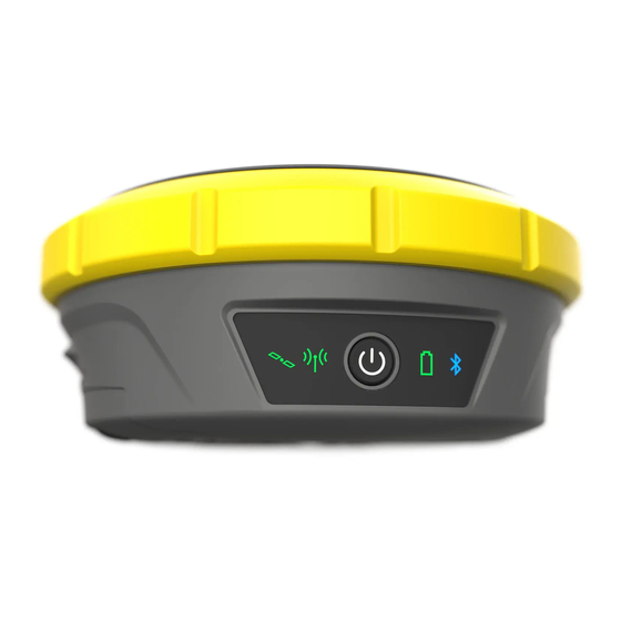
Page 16: User Interface
User Interface Keyboard Description ON/OFF button 22992_001 ON/OFF button Button Status Function ON/OFF If Zenith60 is off Turns on the Zenith60 when held for 2 s. ☞ While the Zenith60 is booting the Power LED is solid green while the other LED are off. - Page 17 Status Description Flashing green Zenith60 is in rover mode. RTK data is being received at the interface of the communication device. Yellow Zenith60 is in RTK base mode. No RTK data is being passed to the interface of the communica- tion device.
-
Page 18: Operation
Operation Equipment Setup 4.1.1 Setting up as a Real-Time Base The following equipment setup is used for real-time base stations. Raw observation data can also be collected for post-processing. Equipment setup - Zenith60 Zenith60 GNSS smart antenna Batteries Carrier Field controller Tribrach Tripod UHF antenna... -
Page 19: Setting Up As A Post-Processing Base
4.1.2 Setting up as a Post-Processing Base The following equipment setup is used for static operations over markers. Equipment setup - Zenith60 Zenith60 GNSS smart antenna Batteries Carrier Tribrach Tripod Field controller 23002_002 Equipment setup Set up the tripod. step-by-step Mount the tribrach on the tripod. -
Page 20: Setting Up As A Real-Time Rover
4.1.3 Setting Up as a Real-Time Rover The following equipment setup is used for real-time rover. Equipment setup - Zenith60 Zenith60 GNSS smart antenna Batteries UHF antenna Pole Holder Field controller 23003_002 Equipment setup Attach the field controller to the pole. step-by-step Clip the field controller into the holder and lock it by tightening the screw on the holder. -
Page 21: Fixing The Field Controller To A Holder And Pole
The instrument is connected to a Personal Computer via serial/USB cable. Install software Start the PC. Download the cable driver from the GeoMax website. Install the cable driver on a PC using a Windows operating system. Connect the Zenith60 to a... -
Page 22: Zenith60 Webmanager
Various required frequencies can be entered into the channel table and assigned to a specific channel number. Sensor firmware The latest version of the instrument firmware is available from the GeoMax website. Licence key Optional GNSS smart antenna licences can be activated with a key file. -
Page 23: Batteries
It is normal for the battery to become warm during charging. Using the chargers recom- • mended by GeoMax, it is not possible to charge the battery if the temperature is too high. For new batteries or batteries that have been stored for a long time (> three months), it is •... -
Page 24: Inserting A Microsd/Sim Card
Inserting a microSD/SIM Card ☞ Keep the card dry. • Use it only within the specified temperature range. • Do not bend the card. • Protect the card from direct impacts. • ☞ Failure to follow these instructions could result in data loss and/or permanent damage to the card. -
Page 25: Working With The Tilt Compensation
Inserting a SIM card 25198_001 ☞ Inserting/removing the SIM card while the Zenith60 is turned on can result in per- manent damage to the card. Only insert/remove the SIM card when the Zenith60 is switched off. ☞ The SIM card is inserted into a slot inside battery compartment A. Open battery compartment A. - Page 26 Points can also be staked out using the tilted pole. Advantages: No need to level the pole • Faster surveying procedures • Faster staking out of points • Diagram α Tilt α 23199_001 Tilt compensation, This step-by-step procedure describes the tilt compensation implemented into the X‑PAD field step-by-step software, ☞...
- Page 27 ☞ The tilt initialisation icon shown on the right appears when the tilt compensation is activated, but not yet initialised to have high accur- acy. Measurements cannot be taken yet. ☞ If IMU does not work, the icon shown on the right side is displayed. This behaviour occurs in rare cases.
-
Page 28: Guidelines For Correct Results With Gnss Surveys
Application example: 0023214_001 Stakeout Inside the selected job go to the Stakeout tab and select one option. Perform a stake out as instructed by the arrow and the values on the left side of the screen. Guidelines for Correct Results with GNSS Surveys Undisturbed satellite sig- Successful GNSS surveys require undisturbed satellite signal reception, especially at the instru- nal reception... -
Page 29: Recovery Process
Recovery Process Recovery process, In case of an incomplete booting process, the battery LED is permanently solid green. The step‑by‑step integrated recovery process could help. ☞ With this recovery process, also the firmware is set back to a pre-defined beta-ver- sion. -
Page 30: Care And Transport
For products for which no container is available use the original packaging or its equivalent. Shipping When transporting the product by rail, air or sea, always use the complete original GeoMax packaging, transport container and cardboard box, or its equivalent, to protect against shock and vibration. -
Page 31: Technical Data
Technical Data Technical Data 6.1.1 Tracking Characteristics Tracking GNSS smart antenna: NovAtel OEM719 multi-frequency with 555 channels. Satellite system Signals GPS tracking L1 C/A, L1C, L2C, L2P, L5 GLONASS tracking L1 C/A, L2 C/A, L2P, L3 BeiDou tracking B1l, B1C, B2l, B2a, B2b, B3l Galileo tracking E1, E5a, E5b, AltBOC, E6 QZSS... -
Page 32: Gnss Antenna Specifications
The accuracies, given as root mean square, are based on measurements processed using GeoMax Geo Office and on real-time measurements. The use of multiple GNSS systems can increase accuracy by up to 30% relative to GPS only. 6.1.3... -
Page 33: Environmental Specifications
Conformity to National Regulations Labelling Zenith60 Model: Zenith60 LTE-UHF-IMU Input: DC 9-28V Art.No: 948898 Developed by GeoMax AG Hexagon Group Sweden Espenstrasse 135 CH-9443 Widnau, Switzerland Made in China Contains FCC IDs: This device complies with part 15 of the FCC Rules. - Page 34 Labelling internal battery 800768 Model: ZBA700 (2ICR19/66) Art.No.:852445 A/S: +82-43-2778115 XU101884-21003A 7.2V 3400mAh 24.5Wh Manufactured: 2021.04 CAUTION: Risk of Fire and Burn. Do Not Open, Crush, Heat Above 60 degree C or Incinerate. Follow Manufacturer‘s Instructions. 22996_001 Guangdong ONE Energy Technology Co.,Ltd. Made in China Antenna Type...
-
Page 35: Dangerous Goods Regulations
Hereby, GeoMax AG declares that the radio equipment type Zenith60 is in com- pliance with Directive 2014/53/EU and other applicable European Directives. The full text of the EU declaration of conformity is available at the following Internet address: https://geomax-positioning.com/partner-area. FCC Part 15, 22, 24 and 27 This equipment has been tested and found to comply with the limits for a Class B digital device, pursuant to part 15 of the FCC Rules. - Page 36 GeoMax has developed Guidelines on “How to carry GeoMax products” and “How to ship GeoMax products” with Lithium batteries. Before any transportation of a GeoMax product, we ask you to consult these guidelines on our web page (http:// www.geomax-positioning.com/dgr) to ensure that you are in accordance with the IATA Dangerous Goods Regulations and that the GeoMax products can be transported correctly.
- Page 38 949606-1.1.0en Original text (949606-1.1.0en) © 2022 GeoMax AG is part of Hexagon AB. All rights reserved. GeoMax AG Espenstrasse 135 9443 Widnau Switzerland geomax-positioning.com...
Need help?
Do you have a question about the Zenith60 Series and is the answer not in the manual?
Questions and answers