Table of Contents
Advertisement
Quick Links
Advertisement
Table of Contents

Related Manuals for GeoMax Zoom80 Series


Summary of Contents for GeoMax Zoom80 Series
- Page 1 GeoMax Zoom80 Series User Manual Version 1.0...
- Page 2 The type and serial number of your product are indicated on the type plate. identification Enter the type and serial number in your manual and always refer to this infor- mation when you need to contact your agency or GeoMax authorised service workshop. Type: _____________________________________ Serial No.:...
- Page 3 Symbols The symbols used in this manual have the following meanings: Type Description DANGER Indicates an imminently hazardous situation which, if not avoided, will result in death or serious injury. WARNING Indicates a potentially hazardous situation or an unin- tended use which, if not avoided, could result in death or serious injury.
- Page 4 Introduction Validity of this Description manual General This manual applies to all Zoom80 series instruments and Zoom80 C controller. Where there are differences between the models they are clearly described. Telescope • Measuring with IR mode: When measuring distances to a reflector with EDM mode "IR", the telescope uses a wide...
- Page 5 Included are detailed descrip- Reference tions of special software/hardware settings and Manual software/hardware functions intended for technical specialists. Refer to the following resources for all Zoom80 documentation/soft- ware: • the GeoMax Zoom80 DVD • www.geomax-positioning.com Zoom80 | 5 Introduction...
- Page 6 Zoom80 | 6 Table of Contents Table of Contents In this manual Chapter Page Description of the System 1.1 System Components 1.2 System Concept 1.2.1 Software Concept 1.2.2 Power Concept 1.2.3 Data Storage and Data Conversion Concept 1.3 Container Contents 1.4 Components 1.4.1 Instrument...
-
Page 7: Table Of Contents
2.3.2 Controller 2.4 Icons Operation 3.1 Instrument Setup 3.2 Instrument Setup for Remote Control 3.2.1 Remote Control Setup 3.2.2 LED Indicators on ZRT80 3.3 Autodetect Behaviour 3.4 Fixing the Controller to a Holder and Pole 3.5 Batteries 3.5.1 Operating Principles 3.5.2 Instrument 3.5.3... - Page 8 Zoom80 | 8 Table of Contents 4.3 Combined Adjustment (l, t, i, c and Aim360) 4.4 Tilting Axis Adjustment (a) 4.5 Adjusting the Circular Level of the Instrument and Tribrach 4.6 Adjusting the Circular Level of the Prism Pole 4.7 Inspecting the Laser Plummet of the Instrument 4.8 Servicing the Tripod Care and Transport 5.1 Transport...
- Page 9 6.6 Laser Classification 6.6.1 General 6.6.2 Distancer, Measurements with Reflectors 6.6.3 Distancer, Measurements without Reflectors 6.6.4 Aim360 6.6.5 Scout360 6.6.6 Navigation Light 6.6.7 Laser Plummet 6.7 Electromagnetic Compatibility EMC 6.8 FCC Statement, Applicable in U.S. Technical Data 7.1 Instrument 7.1.1 General Technical Data of the Instrument 7.1.2 Angle Measurement...
- Page 10 Zoom80 | 10 Table of Contents 7.2 Controller 7.3 Conformity to National Regulations 7.3.1 Instrument 7.3.2 Controller 7.3.3 ZRT80 International Limited Warranty, Software Licence Agreement Index...
- Page 11 1 Description of the System 1.1 System Components Main components Zoom80 C Zoom80 Zoom80_001 Component Description Zoom80 • an instrument for measuring, calculating and capturing data. • comprised of various models with a range of accuracy classes. • combined with Zoom80 C to conduct remote control surveys. •...
- Page 12 An office software consisting of a suite of standard and extended programs for the viewing, exchange and manage- ment of data. Terminology The following terms and abbreviations may be found in this manual: Term Description Total Station Positioning System Remote Control Surveying GeoMax Geo Office...
- Page 13 Term Description Electronic Distance Measurement EDM refers to the laser distancer incorporated into the instrument which enables distance measurement. Three measuring modes are available: • IR mode. This mode refers to the ability to measure distances to prisms. • RL mode. This mode refers to the ability to measure distances without prisms.
- Page 14 Zoom80 | 14 Description of the System Term Description Automation Three automation modes are available: • None: - no automation and no tracking. • Aim360: automatic fine pointing to a prism. • Track360: automatic tracking of an already targeted prism. Scout360 Scout360 refers to the instrument sensor which enables the automatic rapid finding of a prism.
- Page 15 Controller characteristics Zoom80 C Zoom80 instru- ment Use the supplied stylus on the touch screen. Zoom80 | 15 Description of the System...
- Page 16 Zoom80 | 16 Description of the System Zoom80 C Radios for remote control (RCS) are available for the following available radios devices: Radio Modem Description ZRT80 Instrument carry handle with an integrated radio modem and attached radio antenna. Zoom80 C Controller with an integrated radio modem and attached radio antenna.
-
Page 17: Software Concept
1.2 System Concept 1.2.1 Software Concept Description The instrument and controller use the same software concept. Software type Software type Description System This software comprises the central functions of the instru- software ment. It is also referred to as firmware. The programs Survey and Setup are integrated into the firmware and cannot be deleted. - Page 18 Zoom80 | 18 Description of the System Software type Description Application A suite of optional survey-specific application programs is programs available for the instrument. Some of the programs are activated freely and require no license key and others require purchasing and are only acti- vated with a license key.
-
Page 19: Power Concept
1.2.2 Power Concept General Use the GeoMax batteries, chargers and accessories or accessories recom- mended by GeoMax to ensure the correct functionality of the instrument. Power options Type Power supply Instrument One ZBA400 battery fitting into the instrument, OR 11.5 V to 13.5 V power supply via cable. -
Page 20: Data Storage And Data Conversion Concept
Flash card can be inserted and removed. Available capacity: 256 MB. Whilst other CompactFlash cards may be used, GeoMax recommends GeoMax CompactFlash cards and cannot be held responsible for data loss or any other error that may occur when using a non- GeoMax card. - Page 21 Data conversion Export Job data can be exported from a job in a variety of file types. A format can be defined in GGO Format Manager. Refer to the online help of GGO Format Manger for information on creating format files. Import Data can be imported from ASCII, DXF, GSI8 or GSI16 format.
- Page 22 Zoom80 | 22 Description of the System 1.3 Container Contents Container for instrument and accessories a) Data transfer cable b) ZDE100 diagonal eyepiece c) Protective cover for instrument d) Instrument with tribrach and ZRT80 e) Spare stylus Allen key g) CompactFlash cards and covers h) ZCH201 battery charger ZBA400 Battery User manuals...
-
Page 23: Instrument
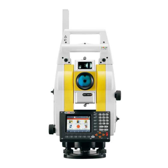
1.4 Components 1.4.1 Instrument Instrument a b c d e f components part 1 of 2 a) Carry handle b) Optical sight c) Telescope, integrating EDM, Aim360 d) NavLight flashing diode - yellow and red e) Scout360, transmitter Scout360, receiver g) Coaxial optics for angle and distance measurement, and exit port of visible laser beam for distance measurements... - Page 24 Zoom80 | 24 Description of the System Instrument components part 2 of 2 k) Vertical drive Focusing ring m) Battery compartment n) Stylus for touch screen o) Screen p) Circular level q) Tribrach footscrew r) Interchangeable eyepiece s) Keyboard Zoom80_002b...
- Page 25 Instrument components for a) ZRT80 b) Bluetooth port Zoom80 | 25 Description of the System...
-
Page 26: Controller
Zoom80 | 26 Description of the System 1.4.2 Controller Upside of controller a) Radio antenna b) Screen c) Keyboard d) Bottom clips e) LEMO port... - Page 27 Underside of controller a) Bottom spring clip for pole holder b) Top clips for pole holder c) Top clips d) Stylus e) Bottom clips LEMO port g) Battery compartment with Compact Flash card compart- ment h) Bluetooth ports (included inside the controller) Zoom80 | 27 Description of the System...
-
Page 28: Instrument
Zoom80 | 28 User Interface 2 User Interface 2.1 Keyboard 2.1.1 Instrument Keyboard / $ % _ @ & * ? ! USER PROG PgUp SHIFT PgDn Zoom80_003... - Page 29 a) Hot keys F7-F12 e) Arrow keys b) Alphanumeric keys SHIFT c) CE, ESC, USER, PROG g) Function keys F1-F6 d) ENTER Keys Description Hot keys F7-F12 • User definable keys to execute commands or access chosen screens. Alphanumeric keys •...
- Page 30 Zoom80 | 30 User Interface Description ENTER • Selects the highlighted line and leads to the next logical dialog/menu. • Starts the edit mode for edit fields. • Opens a list box. SHIFT • Changes between the first and the second level of function keys.
- Page 31 Keys Description combinations PROG plus USER Turns instrument off. SHIFT F12 Calls STATUS Level & Laser Plummet. SHIFT (F11) Calls CONFIGURE Lights, Display, Beeps, Text, Lights page. SHIFT USER Calls QUICK SET Change Settings to:. Pages up. SHIFT Pages down. SHIFT Zoom80 | 31 User Interface...
-
Page 32: Controller
Zoom80 | 32 User Interface 2.1.2 Controller Keyboard PROG a) Function keys F1-F6 b) Alpha keys c) CAPS d) Hot keys F7-F12 e) SPACE, SHIFT CAPS ENTER SPACE g) Arrow keys SHIFT PgUp h) CE, ESC, USER, PROG Numeric keys PgDn Windows key symbol. - Page 33 Keys Description Function keys F1-F6 • Correspond to the six softkeys that appear on the bottom of the screen when the screen is activated. Hot keys F7-F12 • User definable keys to execute commands or access chosen screens. Alpha keys •...
- Page 34 Zoom80 | 34 User Interface Description SPACE • Enters a blank. USER • Calls the user-defined menu. Arrow keys • Move the focus on the screen. ENTER • Selects the highlighted line and leads to the next logical dialog/menu. • Starts the edit mode for edit fields.
- Page 35 2.2 Screen Screen a) Time b) Caption c) Title d) Screen area e) Message line Icons g) ESC h) CAPS SHIFT icon Quick coding icon k) Softkeys Elements of the Element Description screen Time The current local time is shown. Caption Shows location either in Main Menu, under PROG key or USER key.
- Page 36 Zoom80 | 36 User Interface Element Description Screen area The working area of the screen. Message line Messages are shown for 10 s. Icons Shows current status information of the instrument. Refer to "2.4 Icons". Can be used with touch screen. Can be used with touch screen.
- Page 37 2.3 Operating Principles Keyboard and The user interface is operated either by the keyboard or by the touch screen touch screen with supplied stylus. The workflow is the same for keyboard and touch screen entry, the only difference lies in the way information is selected and entered. Selecting Appearance Description...
- Page 38 Zoom80 | 38 User Interface Edit an entire Appearance Description value in input 1) Highlight the field. fields 2) Type numeric and/or alphanumeric characters to overwrite. 3) ENTER or tap outside of the field. Selecting a page Appearance Description To select a page in a screen, do one of the following: PAGE (F6).
- Page 39 Edit an individual Appearance Description character in input A character can be inserted or overwritten. The fields procedure is the same for both cases. 1) Highlight the field. 1) For the keyboard: ENTER. The edit mode is activated where additional functions like insert and overwrite are available.
- Page 40 Zoom80 | 40 User Interface Access special Step Description alphanumeric Highlight the input field. characters for input For the keyboard: ENTER. Toggle to the desired special character set by using the up/down arrow keys. Press the function key assigned to the required character group. Press the function key with the required character.
- Page 41 Appearance and Choicelists have various appearances. selection from a Closed choicelist choicelist Appearance Description Selection Triangles on the right Use the arrow keys indicate further available to change through the choices. list or tap the triangles on the screen. ENTER or tap on the field to access the choicelist. Opening a choicelist reveals either a simple listbox or a comprehensive listbox dialog.
- Page 42 Zoom80 | 42 User Interface Listbox dialog Appearance Description Selection • Choicelist fills the • Highlight the item whole screen. and CONT (F1). • A search field is • To exit without shown. changes press ESC • A scroll bar is shown or tap if necessary.
-
Page 43: Instrument
2.3.1 Instrument Turn instrument Press and hold PROG for 2 s. Turn instrument Step Description The instrument can only be turned off in the Main Menu. step-by-step Press and hold both USER and PROG simultaneously. Press ESC for more than 2 s. Press YES (F6) to continue or NO (F4) to cancel. -
Page 44: Controller
Zoom80 | 44 User Interface 2.3.2 Controller Turn controller on Press PROG (ON) on the keyboard. Turn controller off Option Description Turn The controller can only be turned off in the Main Menu screen or controller in the Windows CE desktop. Press and hold both USER and PROG simultaneously. -
Page 45: Icons
2.4 Icons Description The screen icons display the status information of the instrument. Position of the a) Aim360/Track360/Scout360 a b c d e f g h i icons on the b) Reflector screen c) EDM d) Compensator/face I&II e) Remote control, available on Zoom80 C Bluetooth g) Line/area... - Page 46 Zoom80 | 46 User Interface Icon Description The currently active EDM measurement settings are displayed. Compensator/face Compensator off, out of range or face I&II icon is I&II displayed. Remote control Remote control is turned on. Bluetooth The status of each Bluetooth port and any Bluetooth connection is displayed.
- Page 47 Icon Description Quick coding Shows the quick coding configuration. Can be used with touch screen to turn quick coding on and off. Zoom80 | 47 User Interface...
-
Page 48: Operation
Zoom80 | 48 Operation 3 Operation 3.1 Instrument Setup Description This topic describes an instrument setup over a marked ground point using the laser plummet. It is always possible to set up the instrument without the need for a marked ground point. ... - Page 49 Setup step-by-step SHIFT Zoom80_006 Step Description Shield the instrument from direct sunlight and avoid uneven temper- atures around the instrument. Extend the tripod legs to allow for a comfortable working posture. Position the tripod over the marked ground point, centring it as well as possible.
- Page 50 Zoom80 | 50 Operation Step Description Turn on the instrument by pressing PROG for 2 s. Press SHIFT (F12) to access STATUS Level & Laser Plummet, activating the laser plummet. Move the tripod legs (1) and use the tribrach footscrews (6) to centre the plummet (4) over the ground point.
-
Page 51: Instrument Setup For Remote Control
3.2 Instrument Setup for Remote Control 3.2.1 Remote Control Setup Attaching the ZRT80 to the instrument Zoom80_007 Step Description Refer to "3.1 Instrument Setup" for the initial instrument setup onto a tripod. Remove the instrument carry handle by simultaneously pressing and holding-in the four push buttons. - Page 52 Zoom80 | 52 Operation Step Description Ensure that the interface connection on the underside of the ZRT80 is on the same side as the Bluetooth port. Swing the ZRT80 antenna into an upright position.
- Page 53 Instrument setup for Remote Control a) 360° prism b) Prism pole c) Zoom80 C controller d) ZHR102 holder e) ZRT80 Bluetooth port g) Zoom80 instrument h) Tripod 003630_001 Zoom80 | 53 Operation...
-
Page 54: Led Indicators On Zrt80
Zoom80 | 54 Operation 3.2.2 LED Indicators on ZRT80 LED Indicators Description The ZRT80 has Light Emitting Diode indicators. They indicate the basic ZRT80 status. Diagram of the LED Indicators a b c d Power LED Link LED Data Transfer LED Mode LED... - Page 55 Description of the LED Indicators IF the THEN Power LED power is off. green power is on. Link LED no radio link to remote controller. radio link to remote controller. Data Transfer LED no data transfer to/from remote controller. green or data transfer to/from remote controller.
-
Page 56: Autodetect Behaviour
Zoom80 | 56 Operation 3.3 Autodetect Behaviour Description • The instrument incorporates an autodetect behaviour and automatically detects the following device: • ZRT80 • Whenever a device is attached, the instrument responds with two short beeps. • Whenever a device is removed, the instrument responds with one long beep. -
Page 57: Fixing The Controller To A Holder And Pole
3.4 Fixing the Controller to a Holder and Pole Components of Clamp the ZHR102 a) Ball joint b) Clamp holder c) Tightening screw Holder d) Fixation screw e) Mounting plate Mounting arm g) Ball joint h) Tightening screw Double joint clamp 003628_001 Zoom80 | 57 Operation... - Page 58 Zoom80 | 58 Operation Attaching the Step Description controller to the Remove holder from the travel container. holder step-by-step Insert the pole into the clamp hole. Tighten the clamp with the tightening screw. Adjust the angle and height of the mounting plate and holder on the pole to comfort.
- Page 59 Step Description Hold the controller above the holder and lower the end into the holder. Apply slight pressure in a downward direction and then lower the top part of controller until the unit is clicked into the holder. The guides of the holder aid in this action.
- Page 60 Zoom80 | 60 Operation Step Description After the controller is placed onto the mounting plate ensure that the locking pin is put into the locked position. To lock the locking pin, push up the red button from below.
- Page 61 Detaching the Step Description controller from Unlock the locking pin by pushing down the red button situated on the holder step- top of the mounting plate. by-step Place the palm over the top of the controller until the fingers grip the bar of the holder under the controller.
-
Page 62: Batteries
+68°F if possible. • It is normal for the battery to become warm during charging. Using the chargers recommended by GeoMax, it is not possible to charge the battery if the temperature is too high. • For new batteries or batteries that have been stored for a long time (>... -
Page 63: Instrument
3.5.2 Instrument Insert and remove battery step-by-step Zoom80_008 Step Description Face the instrument so that the vertical drive screw is on the left. The battery compartment is now on the left side of the instrument. Turn the knob to the vertical position, opening the lid of the battery compartment. - Page 64 Zoom80 | 64 Operation Step Description A pictogram of the battery is displayed inside the battery housing. This is a visual aid to assist in placing the battery correctly. Place the battery into the battery housing, ensuring that the contacts are facing outward.
-
Page 65: Controller
3.5.3 Controller Insert and remove battery step-by-step Step Description Turn the controller over to gain access to the battery compartment. Push the slide fastener in the direction of the arrow with the open- lock symbol. Open the battery compartment. Zoom80 | 65 Operation... - Page 66 A pictogram of the battery is displayed inside the battery compart- ment. This is a visual aid to assist in placing the battery correctly. Place the battery into the battery compartment with the GeoMax logo facing to the left. Close the battery compartment by pushing the slide fastener in the...
-
Page 67: Working With The Compactflash Card
3.6 Working with the CompactFlash Card • Keep the card dry. • Use it only within the specified temperature range. • Do not bend the card. • Protect the card from direct impacts. Failure to follow these instructions could result in data loss and/or permanent damage to the card. -
Page 68: Instrument
Zoom80 | 68 Operation 3.6.1 Instrument Insert and remove a CompactFlash card step-by-step Step Description Face the instrument so that the vertical drive screw is on the left. The CompactFlash card compartment is now on the right side of the instrument. - Page 69 Step Description Place the lower end of the CompactFlash card at the lower end of the CompactFlash card compartment. The extended edge of the card has to be on the upper side as shown on the pictogram in the Compact- Flash card compartment.
-
Page 70: Controller
Zoom80 | 70 Operation 3.6.2 Controller Insert and remove a CompactFlash card step-by-step Step Description The CompactFlash card is inserted into a slot inside the battery compartment. Turn the controller over to gain access to the battery compartment. - Page 71 Step Description Push the slide fastener in the direction of the arrow with the open- lock symbol. Open the battery compartment. Pull the battery from the battery compartment. The card should be held with the label for the care instruc- tions upwards and the contacts facing the slot.
- Page 72 Zoom80 | 72 Operation Format a Formatting the CompactFlash card before starting to store data is required if a CompactFlash completely new CompactFlash card is used or if all existing data needs to be card deleted. step-by-step Step Description Main Menu: Tools...\Format Memory Device. TOOLS Format Memory Device <Memory Device: CF Card>...
- Page 73 Step Description NO (F6) to abort the formatting of the CompactFlash card and return to TOOLS Format Memory Device. Once the formatting of the CompactFlash card is completed the system returns to the Main Menu. Zoom80 | 73 Operation...
-
Page 74: Accessing Survey Application Program
Zoom80 | 74 Operation 3.7 Accessing Survey Application Program Access Select Main Menu: Survey. Press PROG. Highlight Survey. CONT (F1). SURVEY Survey Begin CONT (F1) To accept changes and access the subsequent screen. The chosen settings become active. CONF (F2) To access SURVEY Configura- tion. - Page 75 Description of fields Field Option Description <Job:> Choicelist The active job. All jobs from Main Menu: Manage...\Jobs can be selected. <Codelist:> Choicelist No codes are stored in the selected <Job:>. All codelists from Main Menu: Manage...\Codelists can be selected. Output Codes have already been stored in the selected <Job:>.
- Page 76 Zoom80 | 76 Operation Field Option Description <Config Set:> Choicelist The active configuration set. All configura- tion sets from Main Menu: Manage...\Configuration Sets can be selected. The instrument has numerous user configu- ration parameters and functions. This allows a variety of preferences to be addressed. The configuration of the parameters and functions for an individual measuring tech- nique are combined in a configuration set.
-
Page 77: Guidelines For Correct Results
3.8 Guidelines for Correct Results Very short distances may be measured reflectorless in IR mode to well reflecting targets. Note that the distances are corrected with the additive constant defined for the active reflector. Distance measurement Zoom80_009 When measurements are being made using the red laser EDM, the results can be influenced by objects passing between the EDM and the intended target surface. - Page 78 Zoom80 | 78 Operation is triggered, the measurement may be made to the side of the vehicle. The result is the distance to the vehicle, not to the surface of the building. If using the long range measurement mode (> 1000 m, > 3300 ft) to prisms, and an object passes within 30 m of the EDM as the measurement is triggered, the distance measurement may be similarly effected due to the strength of the laser signal.
- Page 79 Aim360/ The Aim360 sensor permits automatic angle and distance measurements to Track360 prisms. The prism is sighted with the optical sight. After initiating a distance measurement, the instrument sights the prism centre automatically. Vertical and horizontal angles and the distance are measured to the centre of the prism.
-
Page 80: Check & Adjust
4 Check & Adjust 4.1 Overview Description GeoMax instruments are manufactured, assembled and adjusted to a high quality. Quick temperature changes, shock or stress can cause deviations and decrease the instrument accuracy. It is therefore recommended to calibrate the instrument from time to time. - Page 81 View current The currently used adjustment errors can be viewed under Main Menu: adjustment Tools...\Check & Adjust...\Current Values. errors Mechanical The following instrument parts can be adjusted mechanically: adjustment • Circular level on instrument and tribrach • Laser plummet • Optical plummet - option on tribrach •...
- Page 82 Zoom80 | 82 Check & Adjust During the manufacturing process, the instrument errors are carefully deter- mined and set to zero. As mentioned above, these errors can change and it is highly recommended to redetermine them in the following situations: •...
- Page 83 Summary of Instrument error Effects Effects Elimination Automati- errors to be with two cally adjusted face corrected electronically measure- with proper ment adjustment c - Line of sight error a - Tilting axis error l - Compensator index error ...
-
Page 84: Preparation
Zoom80 | 84 Check & Adjust 4.2 Preparation Before determining the instrument errors, the instrument has to be levelled using the electronic level. SHIFT (F12) to access STATUS Level & Laser Plummet, Level page. The tribrach, the tripod and the underground should be stable and secure from vibrations or other disturbances. - Page 85 Even after adjustment of the Aim360, the crosshairs may not be positioned exactly on the centre of the prism after an Aim360 measurement has been completed. This outcome is a normal effect. The telescope is not normally posi- tioned exactly on the centre of the prism, to speed up the Aim360 measure- ment.
-
Page 86: Combined Adjustment (L, T, I, C And Aim360)
Select the option: Combined (l,t,i,c,Aim) TOOLS Combined I <Aim Adjust: On> Includes the determination of the Aim360 Hz and V adjustment errors. It is recommended to use a clean GeoMax circular prism as target. Do not use a 360° prism. - Page 87 Step Description Aim the telescope accurately at a target at about 100 m distant. The target must be positioned within ± 9°/± 10 gon of the horizontal plane. The procedure can be started in any telescope face. ± 9° Zoom80 | 87 Check &...
- Page 88 Zoom80 | 88 Check & Adjust Step Description MEAS (F1) to measure and to continue to the next screen. Instruments change automatically to the other face. 180° The fine pointing has to be performed manually in both faces. 180° TOOLS Combined II MEAS (F1) to measure the same target in the other face and to calculate the instrument errors.
- Page 89 Step Description TOOLS Adjustment Accuracy <No.of Meas:> Shows the number of runs executed. One run consists of a measurement in face I and face II. < l Comp:> and similar lines show the standard deviations of the determined adjustment errors. The standard deviations can be calcu- lated from the second run onwards.
- Page 90 Zoom80 | 90 Check & Adjust Next step IF the results THEN to be stored CONT (F1) overwrites the old adjustment errors with the new ones, if the Use status is set to Yes. to be determined REDO (F2) rejects all new determined adjustment errors again and repeats the whole procedure.
-
Page 91: Tilting Axis Adjustment (A)
4.4 Tilting Axis Adjustment (a) Description This adjustment procedure determines the following instrument error: Tilting axis error Determination of The following table explains the most common settings. tilting axis error Step Description step-by-step The Hz collimation error (c) has to be determined before starting this procedure. - Page 92 Zoom80 | 92 Check & Adjust Step Description TOOLS Tilting-Axis Adjustment I Aim the telescope accurately at a target at about 100 m distance or less if not possible. The target must be positioned at least 27°/30 gon above or beneath the horizontal plane. The procedure can be started in any telescope face.
- Page 93 Step Description MEAS (F1) to measure and to continue to the next screen. Instruments change automatically to the other face. The fine pointing has to be 180° performed manually in both faces. 180° TOOLS Tilting-Axis Adjustment II MEAS (F1) to measure the same target in the other face and to calculate the tilting axis error.
- Page 94 Zoom80 | 94 Check & Adjust Step Description TOOLS T-Axis Adjustment Accuracy <No.of Meas:> Shows the number of runs executed. One run consists of a measurement in face I and face II. < a T-axis:> shows the standard deviation of the determined tilting axis error.
- Page 95 Next step IF the results THEN to be stored CONT (F1) overwrites the old tilting axis error with the new one. to be determined REDO (F2) rejects the new determined tilting axis error again and repeats the whole procedure. Refer to step of para- graph "Determination of tilting axis error step-by-step".
- Page 96 Zoom80 | 96 Check & Adjust 4.5 Adjusting the Circular Level of the Instrument and Tribrach Adjusting the circular level step-by-step SHIFT Step Description Place and secure the instrument into the tribrach and onto a tripod. Using the tribrach footscrews, level the instrument with the elec- tronic level.
- Page 97 Step Description a) If both circular levels are centered, no adjustments are neces- sary. b) If one or both circular levels are not centered, adjust as follows: Instrument: If it extends beyond the circle, use the supplied allen key to centre it with the adjustment screws. Turn the instru- ment by 200 gon (180°).
-
Page 98: Adjusting The Circular Level Of The Prism Pole
Zoom80 | 98 Check & Adjust 4.6 Adjusting the Circular Level of the Prism Pole Adjusting the Step Description circular level Suspend a plumb line. step-by-step Use a pole bipod, to align the prism pole parallel to the plumb line. Check the position of the circular level on the prism pole. -
Page 99: Inspecting The Laser Plummet Of The Instrument
The laser plummet is integrated into the vertical axis of the instrument. Under normal conditions of use, the laser plummet does not need adjusting. If an adjustment is necessary due to external influences, the instrument has to be returned to a GeoMax service workshop. Inspecting the laser plummet step-by-step 360°... - Page 100 Zoom80 | 100 Check & Adjust The following table explains the most common settings. Step Description Place and secure the instrument into the tribrach and onto a tripod. Using the tribrach footscrews, level the instrument with the elec- tronic level. SHIFT (F12) to access STATUS Level & Laser Plummet.
- Page 101 3 mm away from the point which was first marked, an adjustment may be required. Inform your nearest GeoMax authorised service workshop. Depending on brightness and surface, the diameter of the laser dot can vary. At 1.5 m it is about 2.5 mm.
-
Page 102: Servicing The Tripod
Zoom80 | 102 Check & Adjust 4.8 Servicing the Tripod Servicing the tripod step-by-step TS_076 The following table explains the most common settings. Step Description The connections between metal and timber components must always be firm and tight. Tighten the leg cap screws moderately, with the supplied allen key. Tighten the articulated joints on the tripod head enough to keep the tripod legs open when lifting the tripod off the ground. -
Page 103: Care And Transport
Always carry the product in its transport container and secure it. Shipping When transporting the product by rail, air or sea, always use the complete original GeoMax packaging, transport container and cardboard box, or its equivalent, to protect against shock and vibration. Shipping, trans-... -
Page 104: Storage
Zoom80 | 104 Care and Transport 5.2 Storage Product Respect the temperature limits when storing the equipment, particularly in summer if the equipment is inside a vehicle. Refer to "7 Technical Data" for information about temperature limits. Field adjustment After long periods of storage inspect the field adjustment parameters given in this user manual before using the product. -
Page 105: Cleaning And Drying
5.3 Cleaning and Drying Product and • Blow dust off lenses and prisms. accessories • Never touch the glass with your fingers. • Use only a clean, soft, lint-free cloth for cleaning. If necessary, moisten the cloth with water or pure alcohol. Do not use other liquids; these can attack the polymer components. - Page 106 Zoom80 | 106 Care and Transport Cables and plugs Keep plugs clean and dry. Blow away any dirt lodged in the plugs of the connecting cables.
-
Page 107: Maintenance
5.4 Maintenance Motorisation An inspection of the motorisation in motorised instruments must be done in a GeoMax authorised service workshop. Following conditions: • After about 4000 hours operation. • Twice a year in case of permanent use of the instrument. -
Page 108: Safety Directions
Zoom80 | 108 Safety Directions 6 Safety Directions 6.1 General Introduction Description The following directions enable the person responsible for the product, and the person who actually uses the equipment, to anticipate and avoid operational hazards. The person responsible for the product must ensure that all users understand these directions and adhere to them. -
Page 109: Intended Use
6.2 Intended Use 6.2.1 Instrument Permitted use • Measuring horizontal and vertical angles. • Measuring distances. • Recording measurements. • Automatic target search, recognition and -tracking. • Visualising the aiming direction and vertical axis. • Remote control of product. • Data communication with external appliances. - Page 110 • Use of products with recognisable damages or defects. • Use with accessories from other manufacturers without the prior explicit approval of GeoMax. • Aiming directly into the sun. • Inadequate safeguards at the working site, for example when measuring on roads.
-
Page 111: Controller
Use after misappropriation. • Use of products with recognisable damages or defects. • Use with accessories from other manufacturers without the prior explicit approval of GeoMax. • Inadequate safeguards at the working site, for example when measuring on roads. •... - Page 112 Zoom80 | 112 Safety Directions Adverse use can lead to injury, malfunction and damage. WARNING It is the task of the person responsible for the equipment to inform the user about hazards and how to counteract them. The product is not to be operated until the user has been instructed on how to work with it.
-
Page 113: Limits Of Use
6.3 Limits of Use Environment Suitable for use in an atmosphere appropriate for permanent human habita- tion: not suitable for use in aggressive or explosive environments. Local safety authorities and safety experts must be contacted before working DANGER in hazardous areas, or close to electrical installations or similar situations by the person in charge of the product. -
Page 114: Responsibilities
Zoom80 | 114 Safety Directions 6.4 Responsibilities Manufacturer of GeoMax AG, CH-9443 Widnau, hereinafter referred to as GeoMax, is respon- the product sible for supplying the product, including the user manual and original acces- sories, in a safe condition. Manufacturers of... - Page 115 WARNING The person responsible for the product must ensure that it is used in accord- ance with the instructions. This person is also accountable for the training and the deployment of personnel who use the product and for the safety of the equipment in use.
-
Page 116: Hazards Of Use
Zoom80 | 116 Safety Directions 6.5 Hazards of Use WARNING The absence of instruction, or the inadequate imparting of instruction, can lead to incorrect or adverse use, and can cause accidents with far-reaching human, material, financial and environmental consequences. Precautions: All users must follow the safety directions given by the manufacturer and the directions of the person responsible for the product. - Page 117 Precautions: Keep at a safe distance from electrical installations. If it is essential to work in this environment, first contact the safety authorities responsible for the elec- trical installations and follow their instructions. CAUTION With the remote control of products, it is possible that extraneous targets will be picked out and measured.
- Page 118 WARNING If computers intended for use indoors are used in the field there is a danger of electric shock. Precautions: Adhere to the instructions given by the computer manufacturer regarding field use with GeoMax products.
- Page 119 Precautions: Do not use the product in a thunderstorm. WARNING Using a battery charger not recommended by GeoMax can destroy the batteries. This can cause fire or explosions. Precautions: Only use chargers recommended by GeoMax to charge the batteries.
- Page 120 Zoom80 | 120 Safety Directions CAUTION During the transport, shipping or disposal of batteries it is possible for inap- propriate mechanical influences to constitute a fire hazard. Precautions: Before shipping the product or disposing of it, discharge the batteries by running the product until they are flat.
- Page 121 Always prevent access to the product by unauthorised personnel. Product-specific treatment and waste management information is available from GeoMax AG. WARNING Only GeoMax authorised service workshops are entitled to repair these products. Zoom80 | 121 Safety Directions...
-
Page 122: Laser Classification
Zoom80 | 122 Safety Directions 6.6 Laser Classification 6.6.1 General General The following chapters provide instructions and training information for the safe use of lasers according to international standard IEC 60825-1 (2007-03) and technical report IEC TR 60825-14 (2004-02). The information enables the person responsible for the product and the person who actually uses the equip- ment, to anticipate and avoid operational hazards. -
Page 123: Distancer, Measurements With Reflectors
6.6.2 Distancer, Measurements with Reflectors General The EDM module built into the product produces a visible laser beam which emerges from the telescope objective. The laser product described in this section is classified as laser class 1 in accordance with: •... - Page 124 ..S.No.: Power: 12V/7,4V ---, 1A max according to ..GeoMax AG CH-9443 Widnau IEC 60825-1 (2007 - 03) Manufactured: ..Made in Switzerland Complies with FDA performance standards for laser products except for deviations pursant to Laser Notice No.50, dated June 24, 2007.
-
Page 125: Distancer, Measurements Without Reflectors
6.6.3 Distancer, Measurements without Reflectors General The EDM module built into the product produces a visible laser beam which emerges from the telescope objective. The laser product described in this section is classified as laser class 3R in accordance with: •... - Page 126 Zoom80 | 126 Safety Directions Description Value (R1000) Maximum average radiant power 5.00 mW Pulse duration 800 ps Pulse repetition frequency 100 MHz - 150 MHz Wavelength 650 nm - 690 nm Beam divergence 0.2 mrad x 0.3 mrad NOHD (Nominal Ocular Hazard Distance) @ 0.25s 80 m / 262 ft CAUTION From a safety perspective, class 3R laser products should be treated as poten-...
- Page 127 CAUTION Potential hazards are not only related to direct beams but also to reflected beams aimed at reflecting surfaces such as prisms, windows, mirrors, metallic surfaces, and so on. Precautions: 1) Do not aim at areas that are essentially reflective, such as a mirror, or which could emit unwanted reflections.
- Page 128 Zoom80 | 128 Safety Directions Labelling Laser Aperture Laser Radiation Avoid direct eye exposure Class 3R Laser Product according to IEC 60825-1 (2007 - 03) Po 5.00 mW Zoom80_011 = 650 - 690 nm a) Laser beam...
- Page 129 Equip.No.: ... S.No.: Power: 12V/7,4V ---, 1A max ..GeoMax AG CH-9443 Widnau Manufactured: ..Made in Switzerland Complies with FDA performance standards for laser products except for deviations pursant to Laser Notice No.50, dated June 24, 2007.
-
Page 130: Aim360
Zoom80 | 130 Safety Directions 6.6.4 Aim360 General The Aim360 built into the product produces an invisible laser beam which emerges from the telescope objective. The laser product described in this section is classified as laser class 1 in accordance with: •... - Page 131 S.No.: ..Power: 12V/7,4V ---, 1A max according to ..GeoMax AG CH-9443 Widnau IEC 60825-1 (2007 - 03) Manufactured: ..Made in Switzerland Complies with FDA performance standards for laser products except for deviations pursant to Laser Notice No.50, dated June 24, 2007.
-
Page 132: Scout360
Zoom80 | 132 Safety Directions 6.6.5 Scout360 General The Scout360 built into the product produces an invisible laser beam which emerges from the front side of the telescope. The laser product described in this section is classified as laser class 1 in accordance with: •... - Page 133 S.No.: ..Power: 12V/7,4V ---, 1A max according to ..GeoMax AG CH-9443 Widnau IEC 60825-1 (2007 - 03) Manufactured: ..Made in Switzerland Complies with FDA performance standards for laser products except for deviations pursant to Laser Notice No.50, dated June 24, 2007.
-
Page 134: Navigation Light
Zoom80 | 134 Safety Directions 6.6.6 Navigation Light General The integrated Navigation Light produces a visible LED beam from the front side of the telescope. The product described in this section, is excluded from the scope of IEC 60825-1 (2007-03): "Safety of laser products". The product described in this section, is classified as exempt group in accordance with IEC 62471 (2006-07) and does not pose any hazard provided that the product is used and maintained in accordance with... - Page 135 ..S.No.: Power: 12V/7,4V ---, 1A max according to ..GeoMax AG CH-9443 Widnau IEC 60825-1 (2001 - 08) Manufactured: ..Made in Switzerland Complies with FDA performance standards for laser products except for deviations pursant to Laser Notice No.50, dated June 24, 2007.
-
Page 136: Laser Plummet
Zoom80 | 136 Safety Directions 6.6.7 Laser Plummet General The laser plummet built into the product produces a visible red laser beam which emerges from the bottom of the product. The laser product described in this section, is classified as laser class 2 in accordance with: •... - Page 137 CAUTION From a safety perspective, class 2 laser products are not inherently safe for the eyes. Precautions: 1) Avoid staring into the beam. 2) Avoid pointing the beam at other people. Zoom80 | 137 Safety Directions...
- Page 138 Equip.No.: ... S.No.: Power: 12V/7,4V ---, 1A max ..GeoMax AG CH-9443 Widnau Manufactured: ..Made in Switzerland Complies with FDA performance standards for laser products except for deviations pursant to Laser Notice No.50, dated June 24, 2007.
- Page 139 Zoom80_016 a) Laser beam b) Exit for laser beam Zoom80 | 139 Safety Directions...
-
Page 140: Electromagnetic Compatibility Emc
Electromagnetic radiation can cause disturbances in other equipment. WARNING Although the product meets the strict regulations and standards which are in force in this respect, GeoMax cannot completely exclude the possibility that other equipment may be disturbed. CAUTION There is a risk that disturbances may be caused in other equipment if the... - Page 141 Although the product meets the strict regulations and standards which are in force in this respect, GeoMax cannot completely exclude the possibility that the product may be disturbed by intense electromagnetic radiation, for example, near radio transmitters, two-way radios or diesel generators.
- Page 142 It can also affect humans and animals. Precautions: Although the product meets the strict regulations and standards which are in force in this respect, GeoMax cannot completely exclude the possibility that other equipment can be disturbed or that humans or animals can be affected. •...
-
Page 143: Fcc Statement, Applicable In U.s
6.8 FCC Statement, Applicable in U.S. The greyed paragraph below is only applicable for products without radio. WARNING This equipment has been tested and found to comply with the limits for a Class B digital device, pursuant to part 15 of the FCC rules. These limits are designed to provide reasonable protection against harmful interference in a residential installation. - Page 144 Zoom80 | 144 Safety Directions WARNING Changes or modifications not expressly approved by GeoMax for compliance could void the user's authority to operate the equipment. Labelling ....
- Page 145 Labelling internal This device complies with part 15 of the FCC Rules. Operation battery ZBA400 is subject to the following two conditions: (1) This device may not cause harmful interference, and (2) this device must accept any interference received, including interference that may cause undesired operation.
- Page 146 15 of the FCC Power: 7.4/12V --- nominal / 0.2A max. Rules. Operation is 100 mW EIRP subject to the following two GeoMax AG conditions: (1) This CH-9443 Widnau device may not cause harmful interference, Manufactured: ..
-
Page 147: Technical Data
7 Technical Data 7.1 Instrument 7.1.1 General Technical Data of the Instrument Magnification: 30 x Telescope Clear objective diameter: 40 mm Focusing: 1.7 m/5.6 ft to infinity Field of view: 1°30’/1.66 gon. 2.7 m at 100 m Compensator Type Setting accuracy Setting range ["] [mgon]... - Page 148 Zoom80 | 148 Technical Data Display: 1/4 VGA (320 x 240 pixels), colour, graphics Control unit capable LCD, illumination, touch screen Keyboard: 34 keys including 12 function keys and 12 alphanu- meric keys, illumination Angle Display: 360°’", 360° decimal, 400 gon, 6400 mil, Distance Display: m, ft int, ft us, ft int inch, ft us inch Position:...
- Page 149 Instrument Dimensions 101.5 mm 101.5 mm 226 mm TPS12_212 203 mm TPS12_213 Instrument: 4.8 - 5.5 kg Weight Tribrach: 0.76 kg Internal battery ZBA400: 0.2 kg Zoom80 | 149 Technical Data...
- Page 150 Zoom80 | 150 Technical Data Recording Data can be recorded onto a CompactFlash card. Type Capacity [MB] Number of measure- ments per MB CompactFlash card 1750 Type: Visible red laser class 2 Laser plummet Location: In standing axis of instrument Accuracy: Deviation from plumb line: 1.5 mm (2 sigma) at 1.5 m instrument height...
- Page 151 Type Operating temperature Storage temperature [°C] [°C] Instrument -20 to +50 -40 to +70 GeoMax Compact- -40 to +80 -40 to +80 Flash cards, all sizes Battery internal -20 to +55 -40 to +70 Bluetooth -30 to +60 -40 to +80...
- Page 152 Zoom80 | 152 Technical Data Humidity Type Protection Instrument Max 95 % non condensing The effects of condensation are to be effectively coun- teracted by periodically drying out the instrument. Reflectors Type Additive Constant Aim36 Scout360 [mm] Circular prism Mini prism +17.5 Mini 0 360°...
- Page 153 Working range: 5 m to 150 m (15 ft to 500 ft) Navigation Light Position accuracy: 5 cm at 100 m (1.97" at 330 ft) Automatic The following automatic corrections are made: corrections • Line of sight error • Vertical index error •...
-
Page 154: Angle Measurement
Zoom80 | 154 Technical Data 7.1.2 Angle Measurement Accuracy Type std. dev. Hz, V, Display least count ISO 17123-3 ["] [mgon] ["] [mgon] Zoom80 S/R Zoom80 S/R Characteristics Absolute, continuous, diametric. -
Page 155: Distance Measurement With Reflectors
7.1.3 Distance Measurement with Reflectors Range Reflector Range A Range B Range C [ft] [ft] [ft] Circular prism 1800 6000 3000 10000 3500 12000 3 prisms 2300 7500 4500 14700 5400 17700 360° prism 2600 1500 5000 2000 7000 360° Mini prism 1500 2600 1000... - Page 156 Zoom80 | 156 Technical Data Measurements can be made to reflector tapes over the entire range without external ancillary optics. Accuracy Accuracy refers to measurements to standard prisms. std. dev. std. dev. Measurement measuring ISO 17123-4, ISO 17123-4, time, typical [s] mode standard prism tape...
-
Page 157: Distance Measurement Without Reflectors
7.1.4 Distance Measurement without Reflectors Range Type Kodak Gray Range D Range E Range F Card [ft] [ft] [ft] accXess1 White side, 2630 1000 3280 >1000 >3280 90 % reflective accXess1 Grey side, 1320 1640 >500 >1640 18 % reflective Range of Measurement: 1.5 m - 1200 m Display unambiguous:... - Page 158 Zoom80 | 158 Technical Data Accuracy Standard measuring std. dev. Measure time, Measure time, ISO 17123-4 typical [s] maximum [s] 0 m - 500 m 2 mm + 2 ppm 3 - 6 >500 m 4 mm + 2 ppm 3 - 6 Object in shade, sky overcast.
-
Page 159: Distance Measurement - Long Range (Lo Mode)
7.1.5 Distance Measurement - Long Range (LO mode) Range Reflector Range A Range B Range C [ft] [ft] [ft] Circular prism 2200 7300 7500 24600 >10000 >32800 Range of measurement: 1000 m to 12000 m Display unambiguous: up to 12000 m Range A: Strong haze, visibility 5 km;... - Page 160 Zoom80 | 160 Technical Data Principle: Phase measurement Characteristics Type: Coaxial, visible red laser Carrier wave: 658 nm Measuring system: System analyser basis 100 MHz - 150 MHz...
-
Page 161: Aim360
7.1.6 Aim360 Range Aim360/ Reflector Range Aim360 Range Track360 Track360 mode mode [ft] [ft] Circular prism 1000 3300 2600 360° prism 2600 2000 360° Mini prism 1150 1000 Mini prism 1600 1300 Reflective tape not qualified 60 mm x 60 mm ... - Page 162 Zoom80 | 162 Technical Data Aim360 angle accuracy Hz, V 1 " (0.3 mgon) Aim360 accuracy (std. dev. ISO 17123-3): with the circular Base Positioning accuracy (std.dev.): ± 1 mm prism System accuracy • The accuracy with which the position of a prism can be determined with with Aim360 Aim360 depends on several factors such as internal Aim360 accuracy, instrument angle accuracy, prism type, selected EDM measuring program...
- Page 163 5” 2” GRZ4 Zoom80_020 Leica GRZ4 prism (360°) Circular prisms and circular Mini prisms Zoom80 | 163 Technical Data...
- Page 164 Zoom80 | 164 Technical Data Aim360 accuracy [mm] Distance measurement [m] " Instrument angle accuracy ["] Maximum speed Maximum tangential speed: 5 m/s at 20 m; 25 m/s at 100 m Maximum radial speed with 5 m/s in Track360 <EDM Mode: Tracking> mode Typical search time in field of view: 1.5 s...
-
Page 165: Scout360
7.1.7 Scout360 Range Reflector Range Track360 [ft] Circular prism 1000 360° prism 300* 1000* Mini prism Measurements at the vertical limits of the fan or under unfavourable atmos- pheric conditions may reduce the maximum range. (*optimally aligned to the instrument) Shortest measuring distance: 1.5 m Typical search time:... -
Page 166: Scale Correction
Zoom80 | 166 Technical Data 7.1.8 Scale Correction Use of scale By entering a scale correction, reductions proportional to distance can be taken correction into account. • Atmospheric correction. • Reduction to mean sea level. • Projection distortion. Atmospheric The slope distance displayed is correct if the scale correction in ppm, mm/km, correction D1 which has been entered corresponds to the atmospheric conditions prevailing at the time of the measurement. - Page 167 Air humidity The air humidity influences the distance measurement if the climate is extremely hot and damp. For high precision measurements, the relative humidity must be measured and entered along with the air pressure and the temperature. Air humidity correction ppm Air humidity correction [mm/km] Relative humidity [%] C°...
- Page 168 Zoom80 | 168 Technical Data Formulas Formula for visible red laser 0.29525 · p 4.126 · 10 · h ΔD = 286.34 - · 10 TS_105 D Atmospheric correction [ppm] Air pressure [mbar] Air temperature [°C] Relative humidity [%] 273.15 (7.5 * t/(237.3 + t)) + 0.7857 If the basic value of 60 % relative humidity as used by the EDM is retained,...
- Page 169 Reduction to The values for D are always negative and are derived from the following mean sea level formula: D D Reduction to mean sea level [ppm] ΔD · 10 Height of EDM above sea level [m] 6.378 * 10 TS_106 Projection distor- The magnitude of the projection distortion is in accordance with the projection...
- Page 170 Zoom80 | 170 Technical Data Atmospheric Atmospheric corrections in ppm with temperature [°C], air pressure [mb] and corrections °C height [m] at 60 % relative humidity. 550 mb 1000 1050 mb 50°C 50°C 40°C 40°C 30°C 30°C 20°C 20°C 10°C 10°C 0°C 0°C...
- Page 171 Atmospheric Atmospheric corrections in ppm with temperature [°F], air pressure [inch Hg] correction °F and height [ft] at 60 % relative humidity. 16 17 18 19 20 21 22 23 24 25 26 27 28 29 30 31 32 inch Hg 130°F 130°F 120°F...
-
Page 172: Reduction Formulas
Zoom80 | 172 Technical Data 7.1.9 Reduction Formulas Measurements a) Mean Sea Level b) Instrument c) Reflector Slope distance Horizontal distance Height difference TS_110 Reflector types The reduction formulas are valid for measurements to all reflector types: • measurements to prisms, to reflector tape and reflectorless measurements. - Page 173 Formulas The instrument calculates the slope distance, horizontal distance, height differ- ence in accordance with the following formulas: Displayed slope distance [m] = D 0 · ( 1 + ppm · 10 ) + mm Uncorrected distance [m] TS_111 ppm Atmospheric scale correction [mm/km] mm Additive constant of the reflector [mm] Horizontal distance [m] = Y - A ·...
- Page 174 Zoom80 | 174 Technical Data Distance meas- In the distance measuring program Averaging, the following values are uring program displayed: Averaging Slope distance as arithmetic mean of all measurements Standard deviation of a single measurement Number of measurements These values are calculated as follows: Slope distance as arithmetic mean of all measurements ·...
- Page 175 The standard deviation of the arithmetic mean of the distance can be calcu- lated as follows: Standard deviation of the arith- metic mean of the distance Standard deviation of a single TS_116 measurement Number of measurements Zoom80 | 175 Technical Data...
-
Page 176: Controller
Zoom80 | 176 Technical Data 7.2 Controller Design Glass reinforced polymer housing with internal battery and radio modem. Control unit Display: 1/4 VGA (320 x 240 pixels), graphics capable LCD, illumination, touch screen, colour display Keyboard: 62 keys including 12 function keys, illumination Angle Display 360°’", 360°... - Page 177 Recording Data can only be recorded on the CompactFlash card. Type Capacity [MB] CompactFlash card • Power Consumption [W] External supply voltage Nominal voltage 12 V DC ( Voltage range 11.5 V-28 V Internal battery Battery Voltage Capacity Operating time, typical ZBA200 Li-Ion 7.4 V...
- Page 178 Zoom80 | 178 Technical Data Environmental Temperature specifications Type Operating temperature [°C] Storage temperature [°C] Controller -30 to +65 -40 to +80 Bluetooth -25 to +65 -40 to +80 Colour -30 to +50 -40 to +80 display Internal -20 to +55 -40 to +70 battery Protection against water, dust and sand...
- Page 179 Interfaces RS232 Bluetooth No handshake LEMO port Class 2 LEMO port Data format for The default values are: RS232 Baud rate: 115200 Parity: None Terminator: CR/LF Data bits: Stop bits: Ports 8 pin LEMO-1 For power and/or communication Zoom80 | 179 Technical Data...
-
Page 180: Conformity To National Regulations
• FCC Part 15 (applicable in US). Conformity to • Hereby, GeoMax AG, declares that the instrument Zoom80 is in compliance national with the essential requirements and other relevant provisions of Directive regulations 1999/5/EC. The declaration of conformity is available from GeoMax AG. -
Page 181: Controller
• FCC Part 15 (applicable in US) Conformity to • Hereby, GeoMax AG, declares that the Zoom80 C is in compliance with the national essential requirements and other relevant provisions of Directive regulations 1999/5/EC. The declaration of conformity is available from GeoMax AG. - Page 182 Zoom80 | 182 Technical Data Output power Type Output power [mW] Bluetooth Spread Spectrum Transceiver < 100 Antenna Type Antenna Gain Connector Frequency [dBi] band [MHz] Bluetooth Integrated antenna Spread Spectrum Detachable /4 2409 - 2435 Transceiver antenna...
-
Page 183: Zrt80
• FCC Part 15 (applicable in US) Conformity to • Hereby, GeoMax AG, declares that the ZRT80 is in compliance with the national essential requirements and other relevant provisions of Directive regulations 1999/5/EC. The declaration of conformity is available from GeoMax AG. - Page 184 Zoom80 | 184 Technical Data Type: /2 dipole antenna Antenna Gain: 2 dBi Connector: Special customized SMB...
-
Page 185: International Limited Warranty, Software Licence Agreement
This product is subject to the terms and conditions set out in the International Limited Warranty Limited Warranty which you can download from the GeoMax home page at http://www.geomax-positioning.com or collect from your GeoMax distributor. The foregoing warranty is exclusive and is in lieu of all other warranties, terms... - Page 186 You must not install or use the software unless you have read and accepted the terms and conditions of the GeoMax Software Licence Agreement. Instal- lation or use of the software or any part thereof, is deemed to be an accept- ance of all the terms and conditions of such Licence Agreement.
-
Page 187: Index
Index Aim360 Accuracy with the circular prism ... 162 A10 ............13 Description ......... 130, 161 Accuracy Positioning of crosshairs ......85 Angle measurement ......154 System accuracy ........ 162 IR mode ..........156 Angle measurement ........ 154 LO mode ..........159 Antenna ..........180 RL mode ..........158 ZRT80 .......... - Page 188 Zoom80 | 188 Index Capacity, memory ........177 Data conversion ........21 CAPS ............33 Data Conversion ........20 CE ............. 29, 33 Data Storage ..........20 Check & Adjust ........80 Data transfer to GGO ........ 21 CompactFlash card Description of the system ......11 Insert ..........
- Page 189 ENTER ..........30, 34 Turn on and turn off ......43 Environmental Specifications ....151 Weight ..........149 ESC ........... 29, 33 Instrument Models ........14 Instrument Setup For remote control ........51 FCC Statement ........143 Intended Use ......... 109 Frequency Band ........180 Internal memory, icon ....... 46 ZRT80 ..........183 International Limited Warranty ....
- Page 190 Zoom80 | 190 Index Labelling ..........145 Navigation Light ZBA200 ..........145 Safety directions ........ 134 Laser Navigation Light NavLight Classification ........122 Technical data ........153 Laser Classification Aim360 ........130, 161 ON ............ 29, 33 Integrated Distancer, Invisible Laser ..123 Output Power ......... 180 Integrated Distancer, Visible Laser ..125 ZRT80 ..........
- Page 191 SPACE ............. 34 Survey Application ........74 Radio Modem Available radios ........16 Recording ........150, 177 Technical Data Reduction Formulas .........172 Dimensions ........176 Reflectors ..........152 Display and keyboard ......176 Remove Environmental specifications ....178 CompactFlash card ....... 70 Ports ..........
- Page 192 Zoom80 | 192 Index Temperature range Product, drying ........105 ZRT80 Touch Screen, operating principles ..... 37 Description ..........14 Transfer raw data to GGO ......21 Setup for remote control ....... 51 Turn instrument off ........34 Technical data ........183 Unlock, keyboard ........
- Page 193 Zoom80 | 193 Index...
- Page 194 GeoMax Zoom80 Series 794008-1.0.0en Original text © 2012 GeoMax AG, Widnau, Switzerland GeoMax AG www.geomax-positioning.com info@geomax-positioning.com...
Need help?
Do you have a question about the Zoom80 Series and is the answer not in the manual?
Questions and answers