Table of Contents
Advertisement
Advertisement
Table of Contents

Related Manuals for GeoMax Zeta125


Summary of Contents for GeoMax Zeta125
- Page 1 GeoMax Zeta125/Zeta125s User Manual Version 1.0...
- Page 2 GeoMax Zeta125/Zeta125s User Manual Version 1.0...
- Page 3 Zeta125/ Zeta125s | 2 Introduction Introduction About the instru- The Zeta125 pipe laser is built to withstand the harsh environment of the ment construction site. The integrated Li-Ion battery with internal charge control provides a long oper- ating time. The battery can be recharged in the instrument. The battery can be recharged while the instrument is working.
- Page 4 All instructions required in order to safely operate and handle the product throughout its life cycle can be found here. Read and follow the User Manual before using the product. Keep all documentation for future reference! Zeta125/ Zeta125s | 3 Introduction...
-
Page 5: Table Of Contents
Zeta125/ Zeta125s | 4 Table of Contents Table of Contents In this manual Chapter Page Safety Directions 1.1 General 1.2 Definition of Use 1.3 Limits of Use 1.4 Responsibilities 1.5 Hazards of Use 1.6 Laser Classification 1.7 Electromagnetic Compatibility EMC 1.8 FCC Statement, Applicable in U.S. - Page 6 Turning On / Turning Off 5.3.2 Auto Alignment Procedure 5.4 Troubleshooting Care and Transport 6.1 Maintenance 6.2 Transport 6.3 Storage 6.4 Cleaning and Drying Technical Data 7.1 Technical Data 7.2 Conformity to National Regulations Zeta125/ Zeta125s | 5 Table of Contents...
-
Page 7: Safety Directions
Zeta125/ Zeta125s | 6 Safety Directions 1 Safety Directions 1.1 General Description The following directions enable the person responsible for the product, and the person who actually uses the equipment, to anticipate and avoid operational hazards. The person responsible for the product must ensure that all users understand these directions and adhere to them. - Page 8 Important paragraphs which must be adhered to in prac- tice as they enable the product to be used in a technically correct and efficient manner. Zeta125/ Zeta125s | 7 Safety Directions...
-
Page 9: Definition Of Use
Zeta125/ Zeta125s | 8 Safety Directions 1.2 Definition of Use Intended use • Remote control of product. • The instrument projects a collimated beam of laser light for the purposes of alignment of gravity flow pipelines. • The laser beam can be detected by viewing it on an opaque red target. -
Page 10: Limits Of Use
The following advice is only valid for battery charger, power adapter and car adapter. Environment Suitable for use in dry environments only and not under adverse conditions. Zeta125/ Zeta125s | 9 Safety Directions... -
Page 11: Responsibilities
Zeta125/ Zeta125s | 10 Safety Directions 1.4 Responsibilities Manufacturer of GeoMax is responsible for supplying the product in a safe condition. This the product includes the product documentation and original accessories. Person respon- The person responsible for the product has the following duties: sible for the •... -
Page 12: Hazards Of Use
Precautions: When setting-up the product, make sure that the accessories are correctly adapted, fitted, secured, and locked in position. Avoid subjecting the product to mechanical stress. Zeta125/ Zeta125s | 11 Safety Directions... - Page 13 Zeta125/ Zeta125s | 12 Safety Directions During the transport, shipping or disposal of batteries it is possible for inap- WARNING propriate mechanical influences to constitute a fire hazard. Precautions: Before shipping the product or disposing of it, discharge the batteries by running the product until they are flat.
- Page 14 Touching live components • Using the product after incorrect attempts were made to carry out repairs Precautions: Do not open the product. Only GeoMax authorised service workshops are enti- tled to repair these products. Zeta125/ Zeta125s | 13 Safety Directions...
- Page 15 Zeta125/ Zeta125s | 14 Safety Directions If the product is improperly disposed of, the following can happen: WARNING • If polymer parts are burnt, poisonous gases are produced which may impair health. • If batteries are damaged or are heated strongly, they can explode and cause poisoning, burning, corrosion or environmental contamination.
-
Page 16: Laser Classification
User Manual due to the low eye hazard level. National laws and local regulations could impose more stringent instruc- tions for the safe use of lasers than IEC 60825-1 (2014-05) and IEC TR 60825-14 (2004-02). Zeta125/ Zeta125s | 15 Safety Directions... - Page 17 Zeta125/ Zeta125s | 16 Safety Directions General The laser source built into the product produces a visible laser beam which emerges from the laser aperture. The laser product described in this section is classified as laser class 3R in accordance with: •...
- Page 18 From a safety perspective, class 3R laser products should be treated as poten- CAUTION tially hazardous. Precautions: 1) Prevent direct eye exposure to the beam. 2) Do not direct the beam at other people. Zeta125/ Zeta125s | 17 Safety Directions...
- Page 19 Zeta125/ Zeta125s | 18 Safety Directions Potential hazards are not only related to direct beams but also to reflected CAUTION beams aimed at reflecting surfaces such as prisms, windows, mirrors, metallic surfaces, etc. Precautions: 1) Do not aim at areas that are essentially reflective, such as a mirror, or which could emit unwanted reflections.
-
Page 20: Electromagnetic Compatibility Emc 19 En
WARNING Although the product meets the strict regulations and standards which are in force in this respect, GeoMax cannot completely exclude the possibility that other equipment may be disturbed. There is a risk that disturbances may be caused in other equipment if the... - Page 21 Although the product meets the strict regulations and standards which are in force in this respect, GeoMax cannot completely exclude the possibility that the product may be disturbed by intense electromagnetic radiation, for example, near radio transmitters, two-way radios or diesel generators.
-
Page 22: Fcc Statement, Applicable In U
• Consult the dealer or an experienced radio/TV technician for help. Changes or modifications not expressly approved by GeoMax for compliance WARNING could void the user's authority to operate the equipment. Zeta125/ Zeta125s | 21... - Page 23 Zeta125/ Zeta125s | 22 Safety Directions Labelling Type: Zeta125s Manufactured for GeoMax AG Art.No.: 829480 CH-9443 Widnau Power: 10.8V / 2.7A Made in the USA S.No.: acc. to IEC 60825-1:2014 / λ = 620-690nm, P = <1mW, t = 1x10 Complies with FDA performance standards for laser products except for deviations pursuant to Laser Notice Nr.
- Page 24 This device complies with part 15 of the FCC Rules. Operation is subject to the following two conditions: (1) This device may not cause harmful interference, and (2) this device must accept any interference received, including interference that may cause undesired operation. 007210_002 Zeta125/ Zeta125s | 23 Safety Directions...
-
Page 25: Container Contents
Zeta125/ Zeta125s | 24 Container Contents 2 Container Contents Container for instrument a) Instrument b) Universal target for 150/200/250 mm pipes c) Auto Target d) Charger e) Leg depot Manual g) Target plate insert for universal target h) Spare battery... -
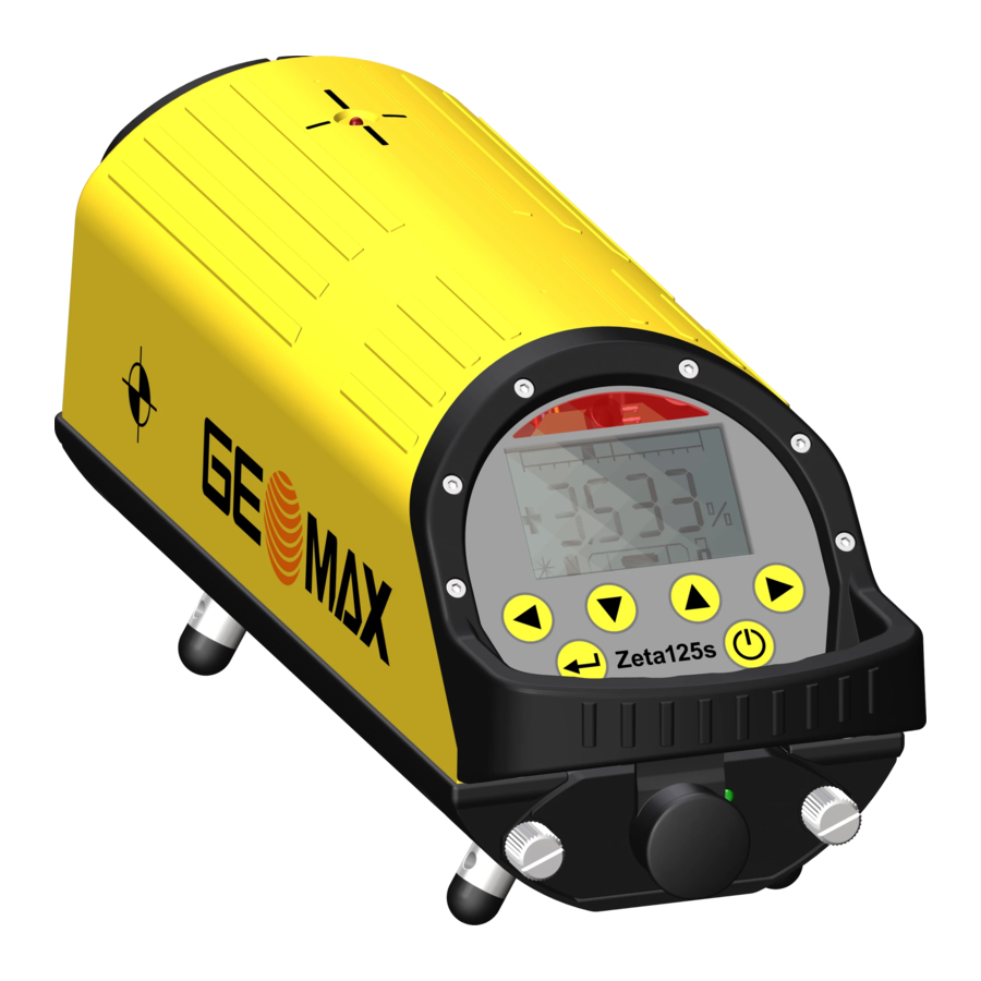
Page 26: Product Overview
3 Product Overview Instrument components a) Laser aperture b) Pivot LED c) 5/8“ thread d) Metal feet e) Display Keypad g) Handle h) Battery Charge socket 008386_001 Zeta125/ Zeta125s | 25 Product Overview... - Page 27 Zeta125/ Zeta125s | 26 Product Overview Keypad Description Left arrow key Down arrow key Up arrow key Right arrow key Enter key ON/OFF key...
-
Page 28: Batteries
+68°F if possible. • It is normal for the battery to become warm during charging. Using the chargers recommended by GeoMax, it is not possible to charge the battery if the temperature is too high. • For Li-Ion batteries, a single refreshing cycle is sufficient. We recommend... -
Page 29: Changing The Battery
Pull the screws tight. Otherwise water can come into the battery case and can damage the battery. To turn on the Zeta125 after long time storage without battery pack: Reinsert the battery pack and press the ON/OFF key for approxi-... - Page 30 Loosen the six screws on the back case of the remote control to open the battery housing. Take the back case. Replace the batteries. Always use three new batteries size AA (LR6) of the same type. Zeta125/ Zeta125s | 29 Product Overview...
- Page 31 Zeta125/ Zeta125s | 30 Product Overview Step Description Do not mix new and old batteries. Mixing old and new batteries decreases the battery lifetime. Check • the correct position of the back case. • that the back case is free from dirt.
-
Page 32: Charging The Battery
Step Description Connect the charger to an AC outlet. Remove the protection cap onto the charge socket of the Zeta125. Attach the plug to the charge socket of the Zeta125. Plug the power cord into an external power supply. Charging starts. -
Page 33: Basic Handling
Zeta125/ Zeta125s | 32 Product Overview 3.2 Basic Handling Turning on Step Description Press the ON/OFF key Each time the laser is switched on, the battery power level is tested. The display shows the start-up screen first and then the capacity of the battery. - Page 34 Refer to "4 Menu" for instructions how to set the entry format to percent or per mil. Step Description Press the Enter key on the keypad. Use the right/left arrow key to set the position of the comma. Press the Enter key to confirm the position of the comma Zeta125/ Zeta125s | 33 Product Overview...
- Page 35 Zeta125/ Zeta125s | 34 Product Overview Step Description Set positive/negative grade. Select and set individual digits for grade values: Use the right/left arrow key to select the digit that must be changed. Use the up/down arrow key to change the value.
- Page 36 Move the target plate in the base until the mark is on the line of the feet length mounted at the laser. Tighten the target plate in place. 150 mm diameter: 008398_001 200 mm diameter: 008399_001 Zeta125/ Zeta125s | 35 Product Overview...
- Page 37 Zeta125/ Zeta125s | 36 Product Overview 250 mm diameter: 008400_001 Setup Step Description Set up the laser in the pipe at the front side. Align the cross axis using the electronic level vial shown in the display. For Zeta125s: Wait until the electronic level vial moves to the middle position.
- Page 38 If the remote control is used from the display 008401_001 side of the laser, the azimuth direction is opposite the arrow direction. Refer to "3.3 Remote Control" for a detailed description of the remote control. Zeta125/ Zeta125s | 37 Product Overview...
- Page 39 Zeta125/ Zeta125s | 38 Product Overview Laser beam Type Description To do flashing Levelling finished Adjust the pipe frequency Grade value reached Permanently on Laser is levelling Wait until level is reached Laser symbol is Flashing constantly flashing Cross Axis Warning...
- Page 40 Press the right and left arrow keys on the keypad simultane- ously for 2 seconds. The laser beam moves back to the centre position automatically. Entered gradient to 0.000% Press the up and down arrow keys simultaneously. Zeta125/ Zeta125s | 39 Product Overview...
- Page 41 Zeta125/ Zeta125s | 40 Product Overview Warning Possible warning messages, their reasons and necessary actions are: messages Warning message Description To do Self-levelling Change the tilt of the laser as shown range exceeded in the display until warning message disappears. Self levelling starts again automatically.
- Page 42 Warning message Description To do Error 0 Data Error 1) Turn laser off and on again. The instrument 2) Check calibration. turns off auto- 3) If the message appears again, matically. contact your service centre. Zeta125/ Zeta125s | 41 Product Overview...
-
Page 43: Remote Control
Key lock function b) Auto alignment function c) Line control adjustment (up move- ment in calibration mode) d) Left arrow key e) Sleep mode (down movement in calibration mode) g) Key for Pivot LED (on the Zeta125) h) Right arrow key 008404_001... - Page 44 All keys on the remote control and on the laser are locked. Locked keys avoid unintentional change when the laser is in use. To deactivate the function press the lock key again. Zeta125/ Zeta125s | 43 Product Overview...
- Page 45 These keys can stop the upward movement of the beam, if the height of the measuring rod is reached earlier. Zeta125: Press the key to turn on the second laser scan beam. The beam position can now be aligned manually or with the right/left arrow keys.
-
Page 46: Menu
SET UP screen >INFO SETTINGS appears. CALIBRATION SERVICE The active menu step is highlighted and > is EXIT displayed in front of the line. 007179_001 Press to open the menu option. Zeta125/ Zeta125s | 45 Menu... - Page 47 Zeta125/ Zeta125s | 46 Menu INFO menu This screen shows: • the software version, • the working hours of the instrument and • internal adjustment values for authorised service centres. All fields are display only fields. Next step Press to return to the SET UP menu.
- Page 48 PRC and PRM. Percent Per mil Next step Step Description Move the cursor to EXIT. Press to return to the SET UP menu. CALIBRATION The settings on this screen change the adjustment of the laser. menu Zeta125/ Zeta125s | 47 Menu...
- Page 49 Zeta125/ Zeta125s | 48 Menu Responsibilities and operation The user can calibrate the instrument. Carry out the calibration attentively and carefully. The user takes full responsibility for failures at measurements and/or consequential damages through wrong calibration. If you feel unsure about doing the calibration, contact your authorised dealer or GeoMax.
- Page 50 Description The calibration has to be done by a qualified authority. Place the pipe laser on a horizontally aligned base. Press to select MAIN AXIS. WAIT is displayed. Wait until SET is displayed. Zeta125/ Zeta125s | 49 Menu...
- Page 51 Zeta125/ Zeta125s | 50 Menu Step Description Use the arrow up and down keys on the remote control to change the calibration value. The height of the laser beam changes with the cali- bration value. Wait until SET is displayed.
-
Page 52: Auto Target
The unit is unsuitable for different application and does not function as intended with non-approved modifications or accessories. Opening the instrument (except exchanging the battery) or making any other modifications does adversely affect the intended function. Zeta125/ Zeta125s | 51 Auto Target... -
Page 53: Product Overview
Zeta125/ Zeta125s | 52 Auto Target 5.1 Product Overview Instrument components a) Secure Knob for pipe target b) Pipe target c) Keypad d) Secure Knobs for battery compartment e) Level vial Rubber feet g) Screws for pipe target holder h) 1/4“ thread... - Page 54 Keypad a) Left LED (red) b) Left arrow key c) ON/OFF LED (green) d) ON/OFF key e) Auto alignment LED (green) Auto alignment key g) Right LED (red) h) Right arrow key 008412_001 Zeta125/ Zeta125s | 53 Auto Target...
- Page 55 Zeta125/ Zeta125s | 54 Auto Target Functions of the Description keys When facing the laser: Moves the laser beam to the left. Switches the auto target on or off. Starts the auto alignment function. When facing the laser: Moves the laser beam to the right.
- Page 56 008422_001 Flashing Auto alignment is running and seeking the auto target in wide mode. 008423_001 Right and left (red): Solid Auto target is in wide mode. 008424_001 Zeta125/ Zeta125s | 55 Auto Target...
- Page 57 Zeta125/ Zeta125s | 56 Auto Target Description Flashing Auto target has timed out. 008425_001 Left (red) and ON/OFF LED (green): Solid In laser receiver mode: The rotating laser beam is to the left of the centre. 008426_001 Right (red) and ON/OFF (green):...
- Page 58 Description Battery level: 75% 008430_001 Battery level: 100% Power off 008431_001 Zeta125/ Zeta125s | 57 Auto Target...
-
Page 59: Changing The Battery
Zeta125/ Zeta125s | 58 Auto Target 5.2 Changing the Battery Insert and The auto target is powered by 4 AA Alkaline batteries. remove the batteries 008432_001 Step Description Remove the two screws from the battery compartment with a coin for example. -
Page 60: Basic Handling
• detector mode The narrow mode is faster than the wide mode. Align the auto target with +/-3° to the centre of the auto target. Zeta125/ Zeta125s | 59 Auto Target... - Page 61 Zeta125/ Zeta125s | 60 Auto Target Switching Step Description between narrow Press the ON/OFF key to power down the auto target. mode and wide mode With the auto target powered down, press and hold the auto align- ment key and at the same time turn on the auto target.
-
Page 62: Auto Alignment Procedure
If necessary, switch the mode. Before you start the auto alignment procedure, ensure that there is free sight between the Zeta125s and the auto target. While the auto alignment is running, nobody must move through the area. Zeta125/ Zeta125s | 61 Auto Target... - Page 63 Zeta125/ Zeta125s | 62 Auto Target Step 3 To start the auto alignment procedure, press the auto alignment key The green auto alignment LED is flashing and the main beam of the Zeta125s switches off. Facing the Zeta125s from the auto target, the Zeta125s pivots to the right.
-
Page 64: Troubleshooting
There was not permanently free sight between Zeta125s and the auto target, for example a person moves through the beam during the auto alignment procedure. b) The alignment of the Zeta125s was not in the +/-3° or +/-6° area of the auto alignment modes. Zeta125/ Zeta125s | 63 Auto Target... - Page 65 Zeta125/ Zeta125s | 64 Auto Target If the Alignment of the Zeta125s was not in +/-3° or +/-6° area, precede as follows: Step Description If the narrow mode is activated: Switch to the wide mode. If the wide mode is activated: Set up the laser again.
-
Page 66: Care And Transport
A calibration interval of one year is recommended. Check the instrument before use. The manufacturer and its representatives are not responsible for any damages resulting from using a maladjusted instru- ment. Zeta125/ Zeta125s | 65 Care and Transport... -
Page 67: Transport
Shipping When transporting the product by rail, air or sea, always use the complete original GeoMax packaging, transport container and cardboard box, or its equivalent, to protect against shock and vibration. Field adjustment Periodically carry out test measurements and perform the field adjustments indicated in the User Manual, particularly after the product has been dropped, stored for long periods or transported. -
Page 68: Cleaning And Drying
40°C/104°F and clean them. Remove the battery cover and dry the battery compartment. Do not repack until everything is dry. Always close the transport container when using in the field. Zeta125/ Zeta125s | 67 Care and Transport... -
Page 69: Technical Data
Zeta125/ Zeta125s | 68 Technical Data 7 Technical Data 7.1 Technical Data Accuracy At 20 °C: ±10" / ± 4.8 mm at 100 m Levelling range: -15% / +45% Range Grade range: Direction: ±10° Grade: –10% / +40% Operation range: >... - Page 70 Ingress protection against water, dust and sand Type Protection Instrument IP68 (IEC 60529) Humidity Type Protection Instrument Max 95 % non condensing The effects of condensation are to be effectively counteracted by periodically drying out the instrument. Zeta125/ Zeta125s | 69 Technical Data...
- Page 71 Zeta125/ Zeta125s | 70 Technical Data Input: 100 - 240 V AC / 47 - 63 V ACHz Charger LDG125 Output: 15 V / 2.0 A Detected wavelength: 635 nm Auto target Detection range: Narrow = +/- 3° Wide = +/- 6°...
Need help?
Do you have a question about the Zeta125 and is the answer not in the manual?
Questions and answers