Table of Contents
Advertisement
Quick Links
Advertisement
Table of Contents

Related Manuals for GeoMax Zeta125 Series


Summary of Contents for GeoMax Zeta125 Series
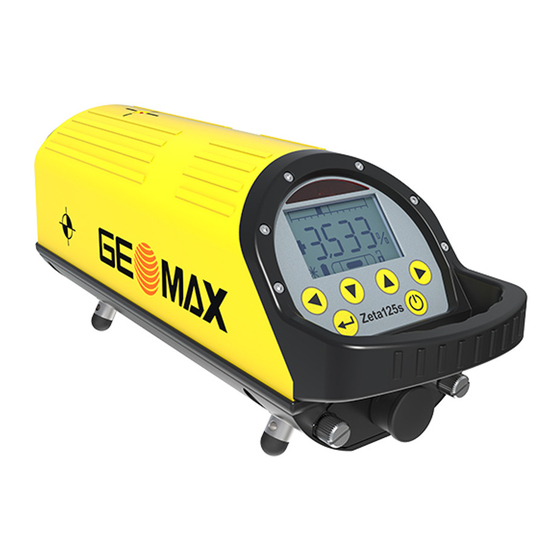
- Page 1 User Manual Version 2.0 English GeoMax Zeta125 Series...
- Page 2 Introduction About the instru- The Zeta125 pipe laser series is built to withstand the harsh environment of ment the construction site. The integrated Li-Ion battery with internal charge control provides a long operating time. The battery can be recharged while the instrument is work- ing.
- Page 3 Models of the Model Description GeoMax Zeta125 Series Zeta125 Red beam pipe laser, Laser class 2 Zeta125 Red beam pipe laser, Laser class 3R Zeta125S Red beam pipe laser with active cross axis compensation Zeta125G Green beam pipe laser, Laser class 2M...
- Page 4 Available Docu- Name Description mentation User Manual All instructions required in order to safely operate and handle the product throughout its life cycle can be found here. ☞ Read and follow the User Manual before using the product. ☞ Keep all documentation for future reference!
-
Page 5: Table Of Contents
Table of Contents Safety Directions General Definition of Use Limits of Use Responsibilities Hazards of Use Laser Classification 1.6.1 Laser Class 1 1.6.2 Laser Class 2/Laser Class 2M 1.6.3 Laser Class 3R Electromagnetic Compatibility (EMC) FCC Statement, Applicable in U.S. Container Contents Product Overview Batteries... -
Page 6: Table Of Contents
Table of Contents 3.1.3 Charging the Battery Basic Handling Remote Control Menu Care and Transport Maintenance Transport Storage Cleaning and Drying Technical Data Technical Data Conformity to National Regulations Dangerous Goods Regulations... -
Page 7: Safety Directions
Safety Directions General Description The following directions enable the person responsible for the product, and the person who actually uses the equipment, to anticipate and avoid opera- tional hazards. The person responsible for the product must ensure that all users under- stand these directions and adhere to them. -
Page 8: Definition Of Use
Safety Directions Type Description Indicates a potentially hazardous situation or an unin- tended use which, if not avoided, may result in minor CAUTION or moderate injury. Indicates a potentially hazardous situation or an unin- NOTICE tended use which, if not avoided, may result in appre- ciable material, financial and environmental damage. -
Page 9: Limits Of Use
Use of products with recognisable damage or defects • Use with accessories from other manufacturers without the prior expli- • cit approval of GeoMax Inadequate safeguards at the working site • Controlling of machines, moving objects or similar monitoring applica- •... - Page 10 Safety Directions WARNING Working in hazardous areas, or close to electrical installations or similar situations Life Risk. Precautions: ▶ Local safety authorities and safety experts must be contacted by the person responsible for the product before working in such conditions. ☞...
-
Page 11: Responsibilities
Responsibilities Manufacturer of GeoMax AG, CH-9443 Widnau, hereinafter referred to as GeoMax, is the product responsible for supplying the product, including the user manual and ori- ginal accessories, in a safe condition. Person respons- The person responsible for the product has the following duties:... -
Page 12: Hazards Of Use
Safety Directions Hazards of Use NOTICE Dropping, misusing, modifying, storing the product for long periods or transporting the product Watch out for erroneous measurement results. Precautions: ▶ Periodically carry out test measurements and perform the field adjust- ments indicated in the User Manual, particularly after the product has been subjected to abnormal use as well as before and after important measurements. - Page 13 CAUTION Not properly secured accessories If the accessories used with the product are not properly secured and the product is subjected to mechanical shock, for example blows or falling, the product may be damaged or people can sustain injury. Precautions: ▶...
- Page 14 Safety Directions For the AC/DC power supply and the battery charger: WARNING Electric shock due to use under wet and severe conditions If unit becomes wet it may cause you to receive an electric shock. Precautions: ▶ If the product becomes humid, it must not be used! ▶...
- Page 15 Either of the following actions may cause you to receive an electric shock: Touching live components • Using the product after incorrect attempts were made to carry out • repairs. Precautions: ▶ Do not open the product! ▶ Only GeoMax authorised service centres are entitled to repair these products. Safety Directions...
- Page 16 Safety Directions WARNING Inappropriate mechanical influences to batteries During the transport, shipping or disposal of batteries it is possible for inap- propriate mechanical influences to constitute a fire hazard. Precautions: ▶ Before shipping the product or disposing it, discharge the batteries by the product until they are flat.
- Page 17 WARNING Exposure of batteries to high mechanical stress, high ambient tem- peratures or immersion into fluids This can cause leakage, fire or explosion of the batteries. Precautions: ▶ Protect the batteries from mechanical influences and high ambient temperatures. Do not drop or immerse batteries into fluids. WARNING Short circuit of battery terminals If battery terminals are short circuited e.g.
- Page 18 • repairs Precautions: ▶ Do not open the product! ▶ Only GeoMax authorised service centres are entitled to repair these products. WARNING Wet or moisture conditions The housing around the battery has wiring which may produce a short-cir- cuit. Precautions: ▶...
- Page 19 CAUTION Before any cleaning procedure, ensure that the instrument is switched off and the battery has been removed. Safety Directions...
- Page 20 Dispose of the product appropriately in accordance with the national regulations in force in your country. Always prevent access to the product by unauthor- ised personnel. Product-specific treatment and waste management information can be received from your GeoMax dealer.
-
Page 21: Laser Classification
Laser Classification General The following chapters provide instructions and training information about laser safety according to international standard IEC 60825-1 (2014-05) and technical report IEC TR 60825-14 (2004-02). The information enables the person responsible for the product and the person who actually uses the equipment, to anticipate and avoid operational hazards. -
Page 22: Laser Class 1
Safety Directions CAUTION Reflected beams aimed at reflecting surfaces Potential hazards are not only related to direct beams but also to reflected beams aimed at reflecting surfaces such as prisms, windows, mirrors, metallic surfaces, etc. Precautions: ▶ Do not aim at areas that are essentially reflective, such as a mirror, or which could emit unwanted reflections. - Page 23 IEC 60825-1 (2014-05): “Safety of laser products” • These products are safe under reasonably foreseeable conditions of opera- tion and are not harmful to the eyes provided that the products are used and maintained in accordance with this User Manual. Zeta125G/Zeta125SG: Description Value...
-
Page 24: Laser Class 2/Laser Class 2M
Safety Directions 1.6.2 Laser Class 2/Laser Class 2M Laser class 2/ The laser source built into the product produces a visible laser beam which Laser class 2M emerges from the laser aperture. The laser product described in this section is classified as laser class 2 in accordance with: IEC 60825-1 (2014-05): “Safety of laser products”... - Page 25 Description Value Beam divergence 0.06 mrad Green laser specifications (Laser class 2M) Description Value Wavelength 520 nm Maximum average radiant power <1.2 mW cw Beam divergence 0.024 mrad Safety Directions...
- Page 26 Avoid staring into the beam or viewing it through optical instruments. ▶ Avoid pointing the beam at other people or at animals. Labelling Zeta125 Model: Zeta125 Manufactured for GeoMax AG Art.No.: 829481 CH-9443 Widnau Power: 10.8V / 2.7A Made in China S.No.: Manufactured: According to IEC 60825-1:2014 / λ...
-
Page 27: Laser Class 3R
Labelling Zeta125G Model: Zeta125G Manufactured for GeoMax AG Art.No.: 938335 CH-9443 Widnau Power: 10.8V / 2.7A Made in China S.No.: 20205001 Manufactured: According to IEC 60825-1:2014 / λ = 520 nm, P = < 1.2 mW cw Complies with 21 CFR 1040.10 and 1040.11 except for conformance with IEC 60825-1 Ed. - Page 28 Safety Directions Direct intrabeam viewing may be hazardous (low eye hazard level), in par- ticular for deliberate ocular exposure. The beam may cause dazzle, flash- blindness and after-images, particularly under low ambient light conditions. The risk of injury for laser class 3R products is limited because of: unintentional exposure would rarely reflect worst case conditions of (e.g.) beam alignment with the pupil, worst case accommodation, inherent safety margin in the maximum permissible exposure to laser...
- Page 29 Green laser specifications Description Value Wavelength 520 nm Maximum average radiant power <5.0 mW cw Beam divergence 0.02 mrad CAUTION Class 3R laser products From a safety perspective, class 3R laser products should be treated as potentially hazardous. Precautions: ▶ Prevent direct eye exposure to the beam.
- Page 30 Safety Directions Labelling Zeta125 US Model: Zeta125 US Manufactured for GeoMax AG Art.No.: 866395 CH-9443 Widnau Power: 10.8V / 2.7A Made in China S.No.: Manufactured: According to IEC 60825-1:2014 / λ = 630 - 680nm, P = < 5.0 mW cw Complies with 21 CFR 1040.10 and 1040.11 except for conformance with...
- Page 31 Labelling Zeta125S Model: Zeta125s Manufactured for GeoMax AG Art.No.: 829480 CH-9443 Widnau Power: 10.8V / 2.7A Made in China S.No.: Manufactured: According to IEC 60825-1:2014 / λ = 635 nm, P < 5.0 mW cw Complies with 21 CFR 1040.10 and 1040.11 except for conformance with IEC 60825-1 Ed.
- Page 32 Safety Directions Labelling Zeta125G Model: Zeta125G Manufactured for GeoMax AG Art.No.: 938336 CH-9443 Widnau Power: 10.8V / 2.7A Made in China S.No.: 20206001 Manufactured: According to IEC 60825-1:2014 / λ = 520nm, P < 5.0 mW cw Complies with 21 CFR 1040.10 and 1040.11 except for conformance with IEC 60825-1 Ed.
- Page 33 Labelling Zeta125SG Model: Zeta125SG Manufactured for GeoMax AG Art.No.: 938334 CH-9443 Widnau Power: 10.8V / 2.7A Made in China S.No.: 20204001 Manufactured: According to IEC 60825-1:2014 / λ = 520nm, P < 5.0 mW cw Complies with 21 CFR 1040.10 and 1040.11 except for conformance with IEC 60825-1 Ed.
- Page 34 Safety Directions Labelling Type: ZRC 125/150 Art.No.: 829482 Manufactured for GeoMax AG CH-9443 Widnau Made in China 8384_002 Labelling Type: Li-Ion battery pack Li-Ion Battery Art.No.: 821886 10.8V / 2.75Ah Manufactured for 12A / 29Wh GeoMax AG S.No.: CH-9443 Widnau...
-
Page 35: Electromagnetic Compatibility (Emc)
WARNING Electromagnetic radiation can cause disturbances in other equipment. Although the product meets the strict regulations and standards which are in force in this respect, GeoMax cannot completely exclude the possibility that other equipment may be disturbed. Safety Directions... - Page 36 Precautions: ▶ Use only the equipment and accessories recommended by GeoMax. When combined with the product, they meet the strict requirements stipulated by the guidelines and standards. When using computers and two-way radios, pay attention to the information about electro-...
- Page 37 Although the product meets the strict regulations and standards which are in force in this respect, GeoMax cannot completely exclude the possibility that the product may be disturbed by intense electromagnetic radiation, for example, near radio transmitters, two-way radios or diesel generators.
-
Page 38: Fcc Statement, Applicable In U
Safety Directions FCC Statement, Applicable in U.S. WARNING This equipment has been tested and found to comply with the limits for a Class B digital device, pursuant to part 15 of the FCC rules. These limits are designed to provide reasonable protection against harm- ful interference in a residential installation. - Page 39 CAUTION Changes or modifications not expressly approved by GeoMax for compli- ance could void the user's authority to operate the equipment. Safety Directions...
-
Page 40: Container Contents
Container Contents Container Contents Container con- tens Instrument Universal target for 150/200/250 mm pipes Charger Leg depot Manual Target plate insert for universal target Spare battery Clip-in target plate for 125 mm pipes Remote control Universal compartment: Manuals, spare cables, target plate etc. 8385_002... -
Page 41: Product Overview
Product Overview Instrument components Laser aperture Pivot LED 5/8“ thread Metal feet Display Keypad Handle Battery Charge socket 008386_001 Product Overview... - Page 42 Product Overview Keypad Description Left arrow key Down arrow key Up arrow key Right arrow key Enter key ON/OFF key...
-
Page 43: Batteries
For Li-Ion batteries, a single discharging and charging cycle is suffi- • cient. We recommend carrying out the process when the battery capa- city indicated on the charger or on a GeoMax product deviates signific- antly from the actual battery capacity available Product Overview... -
Page 44: Changing The Battery
Changing the Battery Insert and remove the battery of the Zeta125 Series 008393_001 Turn off the laser and remove the two screws from the battery pack with a coin for example. The screws are captive at the bat- tery pack to avoid losing them. - Page 45 Pull the screws tight. Otherwise water can come into the battery case and can damage the battery. ☞ To turn on the Zeta125 Series after long time storage without battery pack: Reinsert the battery pack and press the ON/OFF key approximately 3 seconds.
-
Page 46: Charging The Battery
Product Overview ☞ If the LED on the remote control is flashing red while sending, the batteries are low. Loosen the six screws on the back case of the remote control to open the battery housing. Take the back case. Replace the batteries. - Page 47 The charging procedure stops automatically when the maximum charge is reached. The maximum charging time is five hours. After charging is completed, always place the protection cap onto the charge socket of the Zeta125 Series to protect it from dirt. Product Overview...
-
Page 48: Basic Handling
Product Overview Basic Handling Turning on Press the ON/OFF key Each time the laser is switched on, the battery power level is tested. The display shows the start-up screen first and then the capacity of the battery. After initialising the laser beam automatic- ally, the system moves to the last entered grade. - Page 49 Display Line control laser position Laser beam status Battery status Laser beam grade Key lock status Electronic vial 007153_001 Entering a grade Refer to 4 Menu for instructions how to set the entry format to percent. Press the Enter key on the keypad. Set positive/negative grade.
- Page 50 Product Overview Use the up/down arrow key to change the value. Press the Enter key to confirm the setting. The laser adjusts to the setting entered. Setup prepara- Use in large diameter or water bearing pipes tion Unscrew the standard 150 mm feet extensions and screw on the optional available base feet extensions.
- Page 51 Use in pipes with 125 mm diameter Place the laser without metal feet and with the optional clip-in target plate. 008397_001 Use with standard, fixed target Use the same base feet extensions for the laser and the target plate. Use with universal target Adjust the target plate to the pipe diameter.
- Page 52 Product Overview Move the target plate in the base until the mark is on the line of the feet length mounted at the laser. Tighten the target plate in place. 150 mm diameter: 008398_001 200 mm diameter: 008399_001...
- Page 53 Align the cross axis using the electronic level vial shown in the display. For Zeta125 Series: Wait until the electronic level vial moves to the middle position. The cross axis is aligned automatically. Place the target at the opposite side of the pipe. Align the target with the level vial.
- Page 54 Product Overview Aligning the Press the corresponding arrow key on the laser laser line to the or on the remote control. target The beam movement starts slowly and increases in speed while an arrow key is pressed. ☞ On the remote control: The direction of the arrow keys corresponds to the direction of the line movement if the 008401_001...
- Page 55 Type Description To do Flashing Laser is levelling Wait until level is reached constantly Laser symbol is flashing 2 x short Cross Axis Warning Adjust laser position to the Angle error too large level vial Levelling range exceeded Change inclination of the (+/-END) laser until END disappears Flashing...
- Page 56 Product Overview ☞ Ventilate the pipe or place laser and target temporarily on top of the pipe. When the pipe is dry or heated up to the ambient level, the laser spot is stable again. Resetting Line control adjustment - right/left movement Press the right and left arrow keys on the keypad simul- taneously for 2 seconds.
- Page 57 Warning Description To do message Self-levelling Change the tilt of the laser as range exceeded shown in the display until warning message disappears. Self levelling starts again automatically. 007168_001 Laser beam Cross axis Move the instrument so that the flashing 2 x range exceeded level vial in the instrument display short AND...
-
Page 58: Remote Control
Product Overview Warning Description To do message Error 0 Data Error Turn laser off and on again. The instrument Check calibration. turns off auto- If the message appears matically. again, contact your service centre. Remote Control Functions of the The laser can be used with the remote control. remote control... - Page 59 LED and keypad on the remote control Key lock function Auto alignment function Line control adjustment (up move- ment in calibration mode) Left arrow key Sleep mode (down movement in calibration mode) Key for Pivot LED Right arrow key 008404_001 LED on the Remote Control Status Description...
- Page 60 Product Overview Keys Description Use the left and right arrow keys for line control adjustment. The direction of the beam travel corresponds to the arrows, when the remote control is used from the target side. To reset the line control adjustment, press this key for 2 seconds.
- Page 61 Alignment function: This function is used to align the laser beam above the pipe trench. Zeta125 Series: The laser beam moves to the maximum upper position. In this mode the laser beam flashes fast to avoid unintentional use. Use the up and down arrow keys to adjust the height of the laser beam.
- Page 62 Product Overview Description ☞ Remark for Zeta125 Series without automatic cross axis levelling: While aligning, take care that the cross axis is levelled with the level vial in the display.
-
Page 63: Menu
Menu Access to the ☞ The SET UP menu can also be accessed by using the keys on the SET UP Menu remote control. The functions on the remote control are the same and the lock key on the remote control corresponds to the Enter key on the laser keypad. - Page 64 Menu Press to open the menu option. INFO menu This screen shows: Software version • Working hours of the instrument • Internal adjustment values for authorised service centres • All fields are display-only fields. Next step Press to return to the SET UP menu. SETTINGS menu Cross warning settings The settings on this screen define the behaviour of the cross axis warning.
- Page 65 Option Description Press the Enter key to change between ON and OFF. To activate the cross axis warning. The laser beam shortly flashes two times when the cross axis position is out of self-levelling range. To deactivate the cross axis warning. The laser beam stays on continuously, even when the cross axis position is out of self-levelling range.
- Page 66 If you feel unsure about doing the calibration, contact your authorised dealer or GeoMax. Test to see if a horizontal calibration is required Define a horizontal 60 m distance between a reference point and target point.
- Page 67 Measure the height difference between the reference and the tar- get point. Write down the value. Move the laser beam to the target point. Measure the height difference between the target and the refer- ence point. Write down the value. Subtract the values for the two height differences.
- Page 68 Menu Press to select MAIN AXIS. WAIT is displayed. Wait until SET is displayed. Use the arrow up and down keys on the remote control to change the calibration value. The height of the laser beam changes with the calibration value. Wait until SET is displayed.
- Page 69 Next step Move the cursor to EXIT. Press the Enter key to return to the SET UP menu. Menu...
-
Page 70: Care And Transport
Care and Transport Care and Transport Maintenance General informa- All electronic components are enclosed in robust housings to safeguard tion them against mechanical damage. Servicing the system only requires a minimum of time. Periodic checks The user is responsible for regular checks of the instrument by the manu- facturer or one of its authorised service centres. -
Page 71: Storage
Shipping When transporting the product by rail, air or sea, always use the complete original GeoMax packaging, container and cardboard box, or its equivalent, to protect against shock and vibration. Field adjustment Exposing the product to high mechanical forces, for example through fre- quent transport or rough handling, or storing the product for a long time may cause deviations and a decrease in the measurement accuracy. -
Page 72: Cleaning And Drying
Care and Transport Cleaning and Drying Basic Cleaning Basic cleaning is recommended to ensure proper functionality of the instru- ment. Blow off dust. • Use only a clean, soft, lint-free cloth for cleaning. If necessary, • moisten the cloth with water or pure alcohol. Other liquids and solvents than water or alcohol may attack the polymer components. - Page 73 Care and Transport...
-
Page 74: Technical Data
Technical Data Technical Data Technical Data Accuracy Value At 20 °C: ±10" / ± 4.8 mm at 100 m Range Description Value Levelling range −15% / +45% Grade range Direction: ±10° Grade: –10% / +40% Operation range < 200 m Instrument Length [mm] Height [mm]... - Page 75 Weight Value 2.1 kg Power supply Description Value Li-Ion battery, controller charged Internal power supply 230 V/110 V AC power supply • Internal supply voltage with charger Nominal voltage 24 V DC sup- • ply with accessories cable Operating time Value up to 40 h Technical Data...
- Page 76 Technical Data Charging time Value Maximum 5 h, when not in use Environmental Temperature specifications Type Operating temperature Storage temperature [°C] [°C] Instrument −20 to +50 −20 to +70 Ingress protection against water, dust and sand Type Protection Instrument IP68 (IEC 60529)
- Page 77 Humidity Type Protection Instrument Max 95% non condensing The effects of condensation are to be effectively counter- acted by periodically drying out the instrument. Charger LDG125 Description Value Input 100 - 240 V AC / 47 - 63 Hz Output 15 V / 2.0 A Technical Data...
-
Page 78: Conformity To National Regulations
Conformity to National Regulations Conformity to For products without radio transmitter or receiver: National Regula- tions Hereby, GeoMax AG declares that the product/s is/are in • compliance with the essential requirements and other relevant provisions of the applicable European Direct- ives. - Page 79 IATA Dangerous Goods Regulations. ☞ GeoMax has developed Guidelines on “How to carry GeoMax products” and “How to ship GeoMax products” with Lithium bat- teries. Before any transportation of a GeoMax product, we ask you to consult these guidelines on our web page (http:// www.geomax-positioning.com/dgr) to ensure that you are in...
- Page 80 GeoMax AG Espenstrasse 135 9443 Widnau Switzerland geomax-positioning.com 833009-2.0.0en Original text (833009-2.0.0en) © 2021 GeoMax AG is part of Hexagon AB. All rights reserved.
Need help?
Do you have a question about the Zeta125 Series and is the answer not in the manual?
Questions and answers