Table of Contents
Advertisement
Quick Links
Advertisement
Table of Contents

Subscribe to Our Youtube Channel
Related Manuals for GeoMax Zoom80 Series


Summary of Contents for GeoMax Zoom80 Series
- Page 1 GeoMax Zoom80 Series User Manual Version 2.2...
- Page 2 All other trademarks are the property of their respective owners. Validity of this manual Description General This manual applies to all Zoom80 series instruments. Where there are differences between the models they are clearly described. Telescope • Measuring with IR mode: When measuring distances to a reflector with EDM mode "IR", the telescope uses a wide visible red laser beam, which emerges...
-
Page 3: Table Of Contents
Table of Contents In this manual Chapter Page Description of the System System Components System Concept 1.2.1 Software Concept 1.2.2 Power Concept 1.2.3 Data Storage and Data Conversion Concept Container Contents Components 1.4.1 Instrument User Interface Keyboard 2.1.1 Instrument Screen Operating Principles 2.3.1 Instrument... - Page 4 Electromagnetic Compatibility EMC FCC Statement, Applicable in U.S. Technical Data Instrument 7.1.1 General Technical Data of the Instrument 7.1.2 Angle Measurement 7.1.3 Distance Measurement with Reflectors 7.1.4 Distance Measurement without Reflectors 7.1.5 Distance Measurement - Long Range (LO mode) 7.1.6 Aim360 7.1.7 Scout360...
-
Page 5: Description Of The System
The following terms and abbreviations may be found in this manual: Term Description Total Station Positioning System GeoMax Geo Office Electronic Distance Measurement EDM refers to the laser distancer incorporated into the instrument which enables distance measurement. Three measuring modes are available: •... -
Page 6: System Concept
1.2.2 Power Concept General Use the GeoMax batteries, chargers and accessories or accessories recommended by GeoMax to ensure the correct functionality of the instrument. Power options Type... -
Page 7: Data Storage And Data Conversion Concept
Memory device inserted and removed. Available capacity: 256 MB. Whilst other CompactFlash cards may be used, GeoMax recom- mends GeoMax CompactFlash cards and cannot be held respon- sible for data loss or any other error that may occur when using a non-GeoMax card. -
Page 8: Components
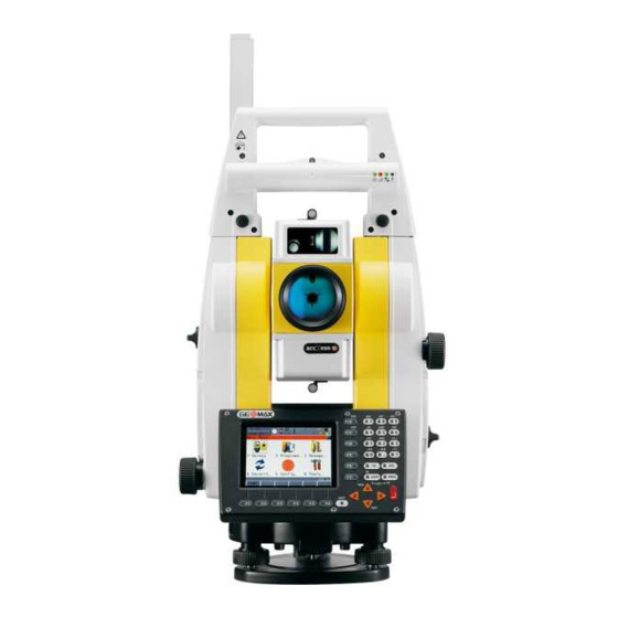
Components 1.4.1 Instrument Instrument components a b c d e f part 1 of 2 a) Carry handle b) Optical sight c) Telescope, integrating EDM, Aim360 d) NavLight flashing diode - yellow and red e) Scout360, transmitter Scout360, receiver g) Coaxial optics for angle and distance measurement, and exit port of visible laser beam for distance measurements h) CompactFlash card compartment Horizontal drive... -
Page 9: User Interface
User Interface Keyboard 2.1.1 Instrument Keyboard / $ % _ @ & * ? ! USER PROG PgUp SHIFT PgDn Zoom80_003 a) Hot keys F7-F12 e) Arrow keys b) Alphanumeric keys SHIFT c) CE, ESC, USER, PROG g) Function keys F1-F6 d) ENTER Keys Description... -
Page 10: Screen
Screen Screen a) Time b) Caption c) Title d) Screen area e) Message line Icons g) ESC h) CAPS SHIFT icon Quick coding icon k) Softkeys Elements of the screen Element Description Time The current local time is shown. Caption Shows location either in Main Menu, under PROG key or USER key. - Page 11 Selecting a page Appearance Description To select a page in a screen, do one of the following: PAGE (F6). Tap on the page tab with the stylus. Edit an individual char- Appearance Description acter in input fields A character can be inserted or overwritten. The procedure is the same for both cases.
-
Page 12: Instrument
Listbox dialog Appearance Description Selection • Choicelist fills the whole • Highlight the item and CONT screen. (F1). • A search field is shown. • To exit without changes press • A scroll bar is shown if neces- ESC or tap sary. -
Page 13: Icons
Icons Description The screen icons display the status information of the instrument. Position of the icons on a b c d e f g h a) Aim360/Track360/Scout360 the screen b) Reflector c) EDM d) Compensator/face I&II e) Bluetooth Line/area g) CompactFlash card h) Battery SHIFT Quick coding... -
Page 14: Operation
Operation Instrument Setup Description This topic describes an instrument setup over a marked ground point using the laser plummet. It is always possible to set up the instrument without the need for a marked ground point. Important features • It is always recommended to shield the instrument from direct sunlight and avoid uneven tempera- tures around the instrument. -
Page 15: Instrument Setup For Remote Control
Instrument Setup for Remote Control 3.2.1 Remote Control Setup Attaching the ZRT81 to the instrument Zoom80_007 Step Description Refer to "3.1 Instrument Setup" for the initial instrument setup onto a tripod. Remove the instrument carry handle by simultaneously pressing and holding-in the four push buttons. Place the ZRT81 onto the instrument by simultaneously pressing and holding-in the four push buttons. -
Page 16: Led Indicators On Zrt81
3.2.2 LED Indicators on ZRT81 LED Indicators Description The ZRT81 has Light Emitting Diode indicators. They indicate the basic ZRT81 status. Diagram of the LED Indicators a b c d Power LED Link LED Data Transfer LED Mode LED Description of the LED Indicators IF the THEN Power LED... -
Page 17: Fixing The Handheld To A Holder And Pole
• For Li-Ion batteries, a single discharging and charging cycle is sufficient. We recommend carrying out the process when the battery capacity indicated on the charger or on a GeoMax product deviates signif- icantly form the actual battery capacity available. -
Page 18: Instrument
3.5.2 Instrument Insert and remove battery step-by-step Zoom80_008 Step Description Face the instrument so that the vertical drive screw is on the left. The battery compartment is now on the left side of the instrument. Turn the knob to the vertical position, opening the lid of the battery compartment. -
Page 19: Working With The Compactflash Card
Working with the CompactFlash Card • Keep the card dry. • Use it only within the specified temperature range. • Do not bend the card. • Protect the card from direct impacts. Failure to follow these instructions could result in data loss and/or permanent damage to the card. ... -
Page 20: Accessing Survey Application Program
Accessing Survey Application Program Access Select Main Menu: Survey. Press PROG. Highlight Survey. CONT (F1). SURVEY Survey Begin CONT (F1) To accept changes and access the subsequent screen. The chosen settings become active. CONF (F2) To access SURVEY Configuration. SETUP (F3) Opens SETUP Station Setup to set station and orientation. -
Page 21: Guidelines For Correct Results
Guidelines for Correct Results Very short distances may be measured reflectorless in IR mode to well reflecting targets. Note that the distances are corrected with the additive constant defined for the active reflector. Distance measurement Zoom80_009 When measurements are being made using the red laser EDM, the results can be influenced by objects passing between the EDM and the intended target surface. -
Page 22: Check & Adjust
Overview Description GeoMax instruments are manufactured, assembled and adjusted to a high quality. Quick temperature changes, shock or stress can cause deviations and decrease the instrument accuracy. It is therefore recommended to calibrate the instrument from time to time. This can be done in the field by running through specific measurement procedures. -
Page 23: Preparation
Preparation Before determining the instrument errors, the instrument has to be levelled using the elec- tronic level. SHIFT (F12) to access STATUS Level & Laser Plummet, Level page. The tribrach, the tripod and the underground should be stable and secure from vibrations or other disturbances. - Page 24 <Aim Adjust: On> Includes the determination of the Aim360 Hz and V adjustment errors. It is recommended to use a clean GeoMax circular prism as target. Do not use a 360° prism. Aim the telescope accurately at a target at about 100 m distant.
-
Page 25: Tilting Axis Adjustment (A)
Tilting Axis Adjustment (a) Description This adjustment procedure determines the following instrument error: Tilting axis error Determination of tilting The following table explains the most common settings. axis error step-by-step Step Description The Hz collimation error (c) has to be determined before starting this procedure. Main Menu: Tools...\Check &... -
Page 26: Adjusting The Circular Level Of The Instrument And Tribrach
Next step IF the results are THEN to be stored CONT (F1) overwrites the old tilting axis error with the new one. to be determined again REDO (F2) rejects the new determined tilting axis error and repeats the whole procedure. Refer to step of paragraph "Determination of tilting axis error step- by-step". -
Page 27: Inspecting The Laser Plummet Of The Instrument
3 mm away from the point which was first marked, an adjustment may be required. Inform your nearest GeoMax authorised service workshop. Depending on brightness and surface, the diameter of the laser dot can vary. At 1.5 m it is about 2.5 mm. -
Page 28: Care And Transport
Shipping When transporting the product by rail, air or sea, always use the complete original GeoMax packaging, transport container and cardboard box, or its equivalent, to protect against shock and vibration. -
Page 29: Maintenance
Maintenance Motorisation An inspection of the motorisation in motorised instruments must be done in a GeoMax authorised service workshop. Following conditions: • After about 4000 hours operation. • Twice a year in case of permanent use of the instrument. Zoom80 | 29... -
Page 30: Safety Directions
Use after misappropriation. • Use of products with recognisable damages or defects. • Use with accessories from other manufacturers without the prior explicit approval of GeoMax. • Aiming directly into the sun. • Inadequate safeguards at the working site, for example when measuring on roads. -
Page 31: Responsibilities
Responsibilities Manufacturer of the GeoMax AG, CH-9443 Widnau, hereinafter referred to as GeoMax, is responsible for supplying the product, product including the user manual and original accessories, in a safe condition. Person responsible for The person responsible for the product has the following duties: the product •... -
Page 32: Laser Classification
Dispose of the product appropriately in accordance with the national regulations in force in your country. Always prevent access to the product by unauthorised personnel. Product-specific treatment and waste management information is available from GeoMax AG. Only GeoMax authorised service workshops are entitled to repair these products. WARNING Laser Classification 6.6.1... -
Page 33: Distancer, Measurements With Reflectors
..S.No.: according to IEC 60825-1 Power: 12V/7,4V ---, 1A max ..GeoMax AG (2007 - 03) CH-9443 Widnau Manufactured: ..Made in .. -
Page 34: Aim360
S.No.: ..Power: 12V/7,4V ---, 1A max ..GeoMax AG CH-9443 Widnau Manufactured: ..Made in ..Complies with FDA performance standards for laser products except for deviations pursant to Laser Notice No.50, dated June 24, 2007. -
Page 35: Scout360
..S.No.: according to IEC 60825-1 Power: 12V/7,4V ---, 1A max ..GeoMax AG (2007 - 03) CH-9443 Widnau Manufactured: ..Made in .. -
Page 36: Navigation Light
..according to IEC 60825-1 Power: 12V/7,4V ---, 1A max ..GeoMax AG (2001 - 08) CH-9443 Widnau Manufactured: ..Made in .. -
Page 37: Electromagnetic Compatibility Emc
Electromagnetic radiation can cause disturbances in other equipment. WARNING Although the product meets the strict regulations and standards which are in force in this respect, GeoMax cannot completely exclude the possibility that other equipment may be disturbed. There is a risk that disturbances may be caused in other equipment if the product is used with accessories... -
Page 38: Fcc Statement, Applicable In U
It can also affect humans and animals. Precautions: Although the product meets the strict regulations and standards which are in force in this respect, GeoMax cannot completely exclude the possibility that other equipment can be disturbed or that humans or animals can be affected. - Page 39 Rules. Operation is Power: 7.4V/12.5V --- / subject to the 0.2A max. following two conditions: (1) This GeoMax AG device may not cause CH-9443 Widnau harmful interference, Manufactured: 20XX and (2) this device Made in ..
-
Page 40: Technical Data Instrument
Technical Data Instrument 7.1.1 General Technical Data of the Instrument Magnification: 30 x Telescope Clear objective diameter: 40 mm Focusing: 1.7 m/5.6 ft to infinity Field of view: 1°30’/1.66 gon. 2.7 m at 100 m Compensator Type Setting accuracy Setting range ["] [mgon] [’]... - Page 41 Temperature cations Type Operating temperature [°C] Storage temperature [°C] Instrument -20 to +50 -40 to +70 GeoMax CompactFlash card -40 to +80 -40 to +80 Battery internal -20 to +55 -40 to +70 Bluetooth -30 to +60 -40 to +80...
-
Page 42: Angle Measurement
Automatic corrections The following automatic corrections are made: • Line of sight error • Vertical index error • Tilting axis error • Standing axis tilt • Earth curvature • Refraction • Circle eccentricity • Aim360 zero point error • Compensator index error 7.1.2 Angle Measurement Accuracy... -
Page 43: Distance Measurement Without Reflectors
7.1.4 Distance Measurement without Reflectors Range Type Kodak Gray Card Range D Range E Range F [ft] [ft] [ft] accXess10 White side, 90 % 2630 1000 3280 >1000 >3280 reflective accXess10 Grey side, 18 % 1320 1640 >500 >1640 reflective Range of Measurement: 1.5 m - 1200 m Display unambiguous:... -
Page 44: Aim360
7.1.6 Aim360 Range Reflector Range Aim360 mode Range Track360 mode Aim360/Track360 [ft] [ft] Circular prism 1000 3300 2600 360° prism 2600 2000 360° Mini prism 1150 1000 Mini prism 1600 1300 Reflective tape not qualified 60 mm x 60 mm ... -
Page 45: Scout360
7.1.7 Scout360 Range Reflector Range Track360 [ft] Circular prism 1000 360° prism 300* 1000* Mini prism Measurements at the vertical limits of the fan or under unfavourable atmospheric conditions may reduce the maximum range. (*optimally aligned to the instrument) Shortest measuring distance: 1.5 m Typical search time: <10 s... - Page 46 Formulas Formula for visible red laser 0.29525 · p 4.126 · 10 · h ΔD = 286.34 - · 10 TS_105 D Atmospheric correction [ppm] Air pressure [mbar] Air temperature [°C] Relative humidity [%] 273.15 (7.5 * t/(237.3 + t)) + 0.7857 If the basic value of 60 % relative humidity as used by the EDM is retained, the maximum possible error in the calculated atmospheric correction is 2 ppm, 2 mm/km.
-
Page 47: Reduction Formulas
Atmospheric correction Atmospheric corrections in ppm with temperature [°F], air pressure [inch Hg] and height [ft] at 60 % rela- °F tive humidity. 16 17 18 19 20 21 22 23 24 25 26 27 28 29 30 31 32 inch Hg 130°F 130°F 120°F... -
Page 48: Conformity To National Regulations
FCC Part 15 (applicable in US). Conformity to national • Hereby, GeoMax AG, declares that the instrument Zoom80 is in compliance with the essential require- regulations ments and other relevant provisions of Directive 1999/5/EC. The declaration of conformity is available from GeoMax AG. -
Page 49: Zrt81
FCC Part 15 (applicable in US) Conformity to national • Hereby, GeoMax AG, declares that the ZRT81 is in compliance with the essential requirements and regulations other relevant provisions of Directive 1999/5/EC. The declaration of conformity is available from GeoMax AG. -
Page 50: Software Licence Agreement
GeoMax. Such software is protected by copyright and other laws and its use is defined and regulated by the GeoMax Software Licence Agreement, which covers aspects such as, but not limited to, Scope of the Licence, Warranty, Intellectual Property Rights, Limitation of Liability, Exclusion of other Assurances, Governing Law and Place of Jurisdiction. -
Page 51: Index
Index Dimensions A10 ................5 Of instrument ............40 Accuracy Distance Measurement Angle measurement ........... 42 Any surface mode ............43 IR mode ..............42 LO mode ..............43 LO mode ..............43 Prism mode .............. 42 RL mode ..............43 Documentation .............. - Page 52 Laser Classification Telescope ..............40 Aim360 .............. 34, 44 Integrated Distancer, Invisible Laser ......33 Temperature Integrated Distancer, Visible Laser ....... 33 Battery Internal Operating ............41 Scout360 ............35, 45 Storage .............. 41 Laser plummet Bluetooth Inspect ..............27 Operating ............
- Page 53 Zoom80 | 53 Index...
- Page 54 GeoMax Zoom80 Series 794008-2.2.0en Original text © 2013 GeoMax AG, Widnau, Switzerland GeoMax AG www.geomax-positioning.com...
Need help?
Do you have a question about the Zoom80 Series and is the answer not in the manual?
Questions and answers