
Related Manuals for Daikin homecontrols EKRRVATU1BA


Summary of Contents for Daikin homecontrols EKRRVATU1BA
- Page 1 Installation and operation manual Daikin Home Controls Radiator Thermostat (UK) EKRRVATU1BA...
- Page 6 1.5 V LR6/mignon/AA batteries Installation and operation manual Documentation © 2022 Daikin Europe N.V., Belgium All rights reserved. This manual may not be reproduced in any format, either in whole or in part, nor may it be duplicated or edited by electronic, mechanical or chemical means, without the written consent of the publisher.
-
Page 7: Table Of Contents
Table of contents Information about this manual ........8 Hazard information ........... 8 Daikin Home Controls ........... 10 Function and accessory overview ......11 Start-up..............13 Connecting further DHC accessories ......13 Mounting ..............14 5.2.1 Mounting the DHC Radiator Thermostat ..16 5.2.2 Danfoss adapter .......... -
Page 8: Information About This Manual
Information about this manual Information about this manual Read this manual carefully before beginning operation with your Daikin Home Controls (DHC) accessories. Keep the manual so you can refer to it at a later date if you need to. If you hand over the device to other persons for use, hand over this manual as well. - Page 9 Hazard information The accessory may only be operated in a dry and dust-free environment and must be protected from the effects of moisture, vibrations, solar or other types of heat radiation, cold and mechanical loads. The accessory is not a toy; do not allow children to play with it.
-
Page 10: Daikin Home Controls
Daikin Home Controls Daikin Home Controls This accessory is part of the DHC ecosystem and commu- nicates with a dedicated wireless connection. All accessories of the system can be configured comfort- ably and individually via the ONECTA app. The available functions provided by the DHC ecosystem in combina- tion with other accessories are described in the DHC Application Guide. -
Page 11: Function And Accessory Overview
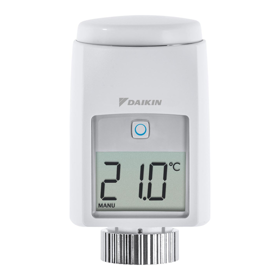
Function and accessory overview Function and accessory overview The DHC Radiator Thermostat enables time-controlled regulation of the room temperature via schedules with in- dividual time slots. You can create 3 different schedules with up to 6 time slots per day. You can comfortably control the DHC Radiator Thermostat in connection with a DHC Access Point via the free ONECTA app. - Page 12 Function and accessory overview Accessory overview (see figure 1): (A) Control wheel/boost button (B) Battery compartment cover System button and LED Display Union nut Display overview (see figure 2): Valve information Setpoint temperature Manual operation Boost mode Operating lock Open window symbol Radio transmission Battery symbol...
-
Page 13: Start-Up
1. Open the ONECTA app. 2. Click on the plus symbol. 3. Select the menu item Add Daikin Home Con- trols. 4. Select Add DHC Accessory. 5. Open the battery compartment (B) by pulling the cover backwards and then down (see figure 7). -
Page 14: Mounting
Start-up You can manually start the connection mode for another 3 minutes by pressing the system button shortly (see figure 3). 8. Follow the instructions in the app. Mounting Read this entire section before starting to mount the accessory. The DHC Radiator Thermostat can be easily installed without draining heating water or intervening in the heat- ing system. No special tools are required, nor does the heating have to be switched off. - Page 15 Start-up • Valf Sanayii • Mertik Maxitrol • Watts • Wingenroth (Wiroflex) • R.B.M • Tiemme • Jaga • Siemens • Idmar By means of the adapters in the delivery, the accessory can also be installed on radiator valves of type Danfoss RA, Danfoss RAV and Danfoss RAVL (see „5.2.2 Danfoss adapter“...
-
Page 16: Mounting The Dhc Radiator Thermostat
Start-up 5.2.1 Mounting the DHC Radiator Thermostat In case of visible damage to the existing radiator, valve or heating pipes, consult a specialist. Remove the old thermostat dial from your radiator valve. 1. Rotate the thermostat dial to the maximum value (N) anti-clockwise (see figure 4). » The thermostat dial no longer presses against the valve spindle, making it easier to remove. -
Page 17: Danfoss Adapter
Start-up Threaded connection with set screw: • 1. Loosen the set screw. 2. Remove the thermostat dial (P). After removing the old thermostat dial you can mount the Radiator Thermostat with the union nut (E) to the radiator valve (see figure 6). If required, you can use one of the supplied adapters for Danfoss valves (see „5.2.2 Danfoss adapter“... - Page 18 Start-up Danfoss RA The Danfoss valve bodies have elongated notches (1) around their circumference, which also ensure that the adapter is properly seated when it snaps on. During installation, make sure that the pins inside the adapter (2) are lined up with the notches (1) on the valve. Make sure that a suitable adapter for the valve is properly clipped on.
- Page 19 Start-up Danfoss RAV The Danfoss valve bodies have elongated notches (1) around their circumference, which also ensure that the adapter is properly seated when it snaps on. During installation, make sure that the pins inside the adapter (2) are lined up with the notches (1) on the valve. Make sure that a suitable adapter for the valve is properly clipped on.
- Page 20 Start-up Danfoss RAVL The Danfoss valve bodies have elongated notches (1) around their circumference, which also ensure that the adapter is properly seated when it snaps on. During installation, make sure that the pins inside the adapter (2) are lined up with the notches (1) on the valve. Make sure that a suitable adapter for the valve is properly clipped on.
-
Page 21: Support Ring
Start-up 5.2.3 Support ring The valves from different manufacturers may have toler- ance fluctuations that make the DHC Radiator Thermostat more loosely seated on the valve. In this case, place the provided support ring (R) into the flange before mounting the device (see figure 5). Adaption run Once the batteries have been inserted, the motor reserves. “ ” and the activity symbol ( are displayed. After mounting the DHC Radiator Thermostat, an adaption run ( ) has to be performed to adapt the acces- soryto the valve. To do this, proceed as follows: 1. -
Page 22: Operation
Operation Operation After connecting and mounting the DHC Radiator Thermostat, simple operations are available directly on the accessory. If the DHC Radiator Thermostat is in standby mode, press the control wheel (A) once before op- eration to activate the accessory. • Temperature: Turn the control wheel (A) to man- ually change the temperature.In automatic mode, manual changes are activated until the next point at which the schedule changes. Afterwards, the... -
Page 23: Replacing Batteries
Replacing batteries The operating lock of the DHC Radiator Thermostat can be activated and deactivated via the ONECTA app. Replacing batteries If the symbol for empty batteries ( ) appears, replace the used batteries by two new LR6/mignon/AA batteries. You must observe the correct battery polarity. To replace the batteries of the accessory, proceed as fol- lows: 1. Open the battery compartment (B) by pulling the cover backwards and then down (see figure 7). -
Page 24: Troubleshooting
Troubleshooting Attention! There is a risk of explosion if the bat- tery is not replaced correctly. Replace only with the same or equivalent type. Never recharge non- rechargeable batteries. Do not throw the batteries into a fire. Do not expose batteries to excessive heat. Do not short-circuit batteries. Doing so will present a risk of explosion. -
Page 25: Duty Cycle
Troubleshooting Duty cycle The wireless DHC accessories operate in the following frequency bands: • 868,000~868,600 MHz • 869,400~869,650 MHz In order to safeguard operation of all devices working in this range, it is legally required to limit the transmission time of devices. Limiting the transmission time minimizes the risk of interference. -
Page 26: Error Codes And Flashing Sequences
Troubleshooting pired. After this period, it will operate normal again. Error codes and flashing sequences Error and flashing Meaning Solution codes Valve drive Check whether the sluggish valve pin is stuck. Actuating Check the fastening range too wide of the DHC Radiator Thermostat Adjustment Check whether the range too valve pin is stuck. - Page 27 Troubleshooting Error and flashing Meaning Solution codes Short orange Radio Wait until the flashing transmission/ transmission is Attempting to completed. transmit 1x long green Transmission Continue the oper- lighting confirmed ation. 1x long red Duty cycle Try again (see „8.2 lighting exceeded or Duty cycle“...
-
Page 28: Restore Factory Settings
Restore factory settings Restore factory settings The factory settings of the accessory can be re- stored. If you do this, you will lose all your settings. To restore the factory settings of the accessory, proceed as follows: 1. Open the battery compartment (B) by pulling the cover backwards and then down (see figure 7). 2. Remove the batteries. 3. -
Page 29: Maintenance And Cleaning
Maintenance and cleaning Maintenance and cleaning The accessory does not require you to carry out any maintenance other than replacing the battery when necessary. Enlist the help of an expert to carry out any repairs. Clean the accessory using a soft, lint-free cloth that is clean and dry. You may dampen the cloth a little with luke- warm water in order to remove more stubborn marks. -
Page 30: General Information About Radio Operation
The range of transmission within buildings can dif- fer greatly from that available in the open air. Be- sides the transmitting power and the reception characteristics of the receiver, environmental fac- tors such as humidity in the vicinity have an im- portant role to play, as do on-site structural/ screening conditions. Hereby, Daikin Europe N.V. declares that the radio equip- ment type DHC EKRRVATU1BA is in compliance with the Directive 2014/53/EU. The original declaration of confor- mity is available from the EKRRVATU1BA product pages. https://qr.daikin.eu/?N=EKRRVATU1BA... -
Page 31: Technical Specifications
Technical specifications Technical specifications Device name: EKRRVATU1BA Supply voltage: 2x 1.5 V LR6/mignon/AA Current consumption: 120 mA max. Battery life (typ.): 2 years Degree of protection: IP20 Degree of pollution: Ambient temperature: 0 to 50 °C Dimensions (W x H x D): 58 x 71 x 97 mm Weight: 205 g (incl. batteries) Radio frequency band: 868.0 - 868.6 MHz 869.4 - 869.65 MHz... - Page 32 Technical specifications Instructions for disposal Do not dispose of the device with regular domestic waste! Electronic equipment must be disposed of at local collection points for waste electronic equipment in compliance with the Waste Electrical and Electronic Equipment Directive. Information about conformity The CE sign is a free trading sign addressed ex- clusively to the authorities and does not include any warranty of any properties.
- Page 36 Free download of the ONECTA app! 4P687168-1 - 2022.04...
Need help?
Do you have a question about the homecontrols EKRRVATU1BA and is the answer not in the manual?
Questions and answers