
Related Manuals for Daikin homecontrols EKRCTRDI2BA


Summary of Contents for Daikin homecontrols EKRCTRDI2BA
- Page 1 Installer and user reference guide Daikin Home Controls Room Thermostat – 1 EKRCTRDI2BA...
- Page 4 click...
- Page 6 60 mm...
- Page 7 click...
- Page 10 Installation and operation manual Supplement sheet with safety instructions Documentation © 2022 Daikin Europe N.V., Belgium All rights reserved. This manual may not be reproduced in any format, either in whole or in part, nor may it be duplicated or edited by electronic, mechanical or chemical means, without the written consent of the publisher.
-
Page 11: Table Of Contents
Table of contents Information about this manual ........ 13 Hazard information ..........13 Daikin Home Controls ........... 15 Function and accessory overview ......16 Start-up..............18 Connecting DHC accessories ........18 5.1.1 Connecting to the DHC Access Point ....18 Mounting .............. - Page 12 12 General information about radio operation ..... 35 13 Technical specifications .......... 36...
-
Page 13: Information About This Manual
Information about this manual Read this manual carefully before beginning operation with your Daikin Home Controls (DHC) accessories. Keep the manual so you can refer to it at a later date if you need to. If you hand over the accessory to other persons for use, hand over this manual as well. - Page 14 Hazard information The accessory may only be operated in a dry and dust-free environment and must be protected from the effects of moisture, vibrations, solar or other types of heat radiation, cold and mechanical loads. The accessory is not a toy; do not allow children to play with it.
-
Page 15: Daikin Home Controls
Daikin Home Controls Daikin Home Controls This accessory is part of the DHC ecosystem and commu- nicates with a dedicated wireless connection. All accessories of the system can be configured comfort- ably and individually via the ONECTA app. The available... -
Page 16: Function And Accessory Overview
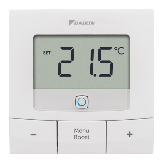
Function and accessory overview Function and accessory overview The DHC Room Thermostat enables time-controlled reg- ulation of your conventional radiators with DHC Radiator Thermostats, or of your floor heating in combination with DHC Floor Heating Controllers, and adjusts heating time slots to your individual needs. - Page 17 Function and accessory overview Display overview (see figure 2): Setpoint/actual temperature Open window symbol Battery symbol Radio transmission Boost function Manual mode* Automatic mode* Holiday mode* Heating Cooling Operating lock* Setpoint temperature Overview of time slots Date and time Offset temperature* Programming a schedule* Days of the week * see “6 Configuration” on page 24...
-
Page 18: Start-Up
Start-up Start-up Connecting DHC accessories Read this entire section before starting to connect other accessories. To integrate the DHC Room Thermostat into your ecosys- tem and enable it to communicatie with other accessories, you must connect them first. You can connect the DHC Room Thermostat to the DHC Access Point via the ONECTA app. - Page 19 Point, proceed as follows: 1. Open the ONECTA app. 2. Click on the plus symbol (+). 3. Select the menu item Add Daikin Home Controls. 4. Select Add DHC Accessory (see figure 4). 5. Open the battery compartment (G) using a slotted screwdriver to loosen the wall mounting plate (see figure 3).
-
Page 20: Mounting
Start-up Mounting Read this entire section before starting to mount the accessory. You can fix the DHC Room Thermostat to a wall with: • the supplied double-sided adhesive strips, or • the supplied screws. You can also mount the DHC Room Thermostat on a flush-mounted box. 5.2.1 Adhesive strip mounting To mount the DHC Room Thermostat using the adhesive strips, proceed as follows: 1. -
Page 21: Screw Mounting
Start-up 4. Remove the protective film from the adhesive strips (see figure 7). 5. Press the assembled DHC Room Thermostat with the back side to the wall (see figure 7). 5.2.2 Screw mounting To mount the DHC Room Thermostat with screws, proceed as follows: 1. Choose a site for installation. Make sure that no electricity or similar lines run in the wall at this location! 2. -
Page 22: Flush-Mounted Box Mounting
Start-up mounting plate to the wall (see figure 9). 6. Insert the electronic unit (A) into the wall mounting plate (see figure 10). Make sure that the electronic unit properly engages into the wall mounting plate. 5.2.3 Flush-mounted box mounting You can mount the DHC Room Thermostat on a flush-mounted box using the screw holes (see figure 11). - Page 23 Start-up *Specialist knowledge required for installation: The following specialist knowledge is particularly important during installation: • The “5 safety rules” to be used: Disconnect from mains; Safeguard from switching on again; Check that system is de-energised; Earth and short cir- cuit; Cover or cordon off neighbouring live parts;...
-
Page 24: Configuration
Configuration Configuration The configuration of the accessory can be set up complete- ly in the ONECTA app. For further information on configura- tion of the accessory without using the DHC Access Point, see the DHC Application Guide. The following modes and settings can be adjusted: Automatic mode Manual mode Offset temperature (not yet available) Programming a schedule Operating lock (not yet available) Holiday mode Automatic mode In automatic mode, the temperature is controlled in accor- dance with the set schedule. -
Page 25: Manual Mode
Configuration Manual mode In manual mode, the temperature is controlled in accor- dance with the current temperature set via the push-but- tons (D + F). The temperature remains activated until the next manual change. Offset temperature (not yet available) As the temperature is measured on the DHC Room Thermostat, the temperature distribution can vary through- out a room. To adjust this, a temperature offset of ±3.5 °C can be set. If a nominal temperature of e.g. 20 °C is set... -
Page 26: Operating Lock (Not Yet Available)
Holiday mode can be activated in the ONECTA app. It will put your system into standby. The holiday mode is visual- ized on your Daikin Altherma and on the Air Conditioning units in the ONECTA App. For further information, see the DHC Application Guide. -
Page 27: Operation
Operation Operation After connecting and mounting the DHC Room Thermostat, simple operations are available directly on the accessory. Temperature: Press the plus and minus buttons • (D + F) to manually change the temperature. In automatic mode, manual changes are activated until the next point at which the schedule changes. -
Page 28: Replacing Batteries
Replacing batteries Replacing batteries If the symbol for empty batteries ( ) appears, replace the used batteries by two new LR6/mignon/AA batteries. You must observe the correct battery polarity. To replace the batteries of the accessory, proceed as fol- lows: 1. Once mounted, the electronic unit (A) can easily be pulled out of the wall mounting plate. -
Page 29: Troubleshooting
Troubleshooting Attention! There is a risk of explosion if the battery is not replaced correctly. Replace only with the same or equivalent type. Never recharge non- rechargeable batteries. Do not throw the batteries into a fire. Do not expose batteries to excessive heat. -
Page 30: Duty Cycle
Troubleshooting Duty cycle The wireless DHC accessories operate in the following fre- quency bands: • 868,000~868,600 MHz • 869,400~869,650 MHz In order to safeguard operation of all devices working in this range, it is legally required to limit the transmission time of devices. -
Page 31: Error Codes And Flashing Sequences
Troubleshooting this period, it will operate normal again. Error codes and flashing sequences Error and flashing Meaning Solution codes Battery Battery Replace the symbol ( voltage too low batteries of the accessory (see “8 Replacing batteries” on page 28). Antenna Communica- Check the con- symbol flash- tion problem nection with the... - Page 32 Troubleshooting Error and flashing Meaning Solution codes Short orange Connection Follow the flashing mode active instructions in (every 10 the app to add seconds) accessory (see “5.1 Connecting DHC accessories” on page 18). Short orange Batteries empty Replace the batter- lighting (after ies (see “8 Replac- green or red ing batteries” on confirmation)
-
Page 33: Restore Factory Settings
Restore factory settings Restore factory settings The factory settings of the accessory can be re- stored. If you do this, you will lose all your settings. To restore the factory settings of the accessory, proceed as follows: 1. Once mounted, the electronic unit (A) can easily be pulled out of the wall mounting plate. -
Page 34: Maintenance And Cleaning
Maintenance and cleaning Maintenance and cleaning The accessory does not require you to carry out any maintenance other than replacing the battery when necessary. Enlist the help of an expert to car- ry out any repairs. Clean the accessory using a soft, lint-free cloth that is clean and dry. - Page 35 Hereby, Daikin Europe N.V. declares that the radio equip- ment type DHC EKRCTRDI2BA is in compliance with the Directive 2014/53/EU. The original declaration of confor- mity is available from the EKRCTRDI2BA product pages.
- Page 36 Technical specifications Technical specifications Device name: EKRCTRDI2BA Supply voltage: 2x 1.5 V LR6/mignon/AA Current consumption: 40 mA max. Battery life (typ.): 5 years Degree of protection: IP20 Degree of pollution: Ambient temperature: 0 to 50 °C Dimensions (W x H x D): 85 x 85 x 22 mm Weight: 140 g (including batteries) Radio frequency band: 868.0-868.60 MHz 869.4-869.65 MHz Maximum radiated power: 10 dBm Receiver category: SRD category 2...
- Page 37 Technical specifications Instructions for disposal Do not dispose of the device with regular domestic waste! Electronic equipment must be disposed of at local collection points for waste electronic equip- ment in compliance with the Waste Electrical and Electronic Equipment Directive. Information about conformity The CE sign is a free trading sign addressed exclu- sively to the authorities and does not include any warranty of any properties.
- Page 40 Technical specifications Free download of the ONECTA app! 4P687364-1 - 2022.04...
Need help?
Do you have a question about the homecontrols EKRCTRDI2BA and is the answer not in the manual?
Questions and answers