
Related Manuals for Daikin Home Controls EKRRVATR2BA


Summary of Contents for Daikin Home Controls EKRRVATR2BA
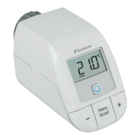
- Page 1 Installer and user reference guide Daikin Home Controls Radiator Thermostat EKRRVATR2BA...
- Page 8 Installation and operation manual Supplement sheet with safety instructions Documentation © 2022 Daikin Europe N.V., Belgium All rights reserved. This manual may not be reproduced in any format, either in whole or in part, nor may it be duplicated or edited by electronic, mechanical or chemical means, without the written consent of the publisher.
-
Page 9: Table Of Contents
Table of contents Information about this manual ........ 11 Hazard information ..........11 Daikin Home Controls ..........13 Function and accessory overview ......14 Start-up..............16 Connecting DHC accessories ........16 5.1.1 Connecting to the DHC Access Point ....16 Mounting .............. - Page 10 11 Maintenance and cleaning ........34 12 General information about radio operation ..... 35 13 Technical specifications .......... 36...
-
Page 11: Information About This Manual
Information about this manual Read this manual carefully before beginning operation with your Daikin Home Controls (DHC) accessories. Keep the manual so you can refer to it at a later date if you need to. If you hand over the accessory to other persons for use, hand over this manual as well. - Page 12 Hazard information For safety and licensing reasons (CE), unautho- rized change and/or modification of the accessory is not permitted. The accessory is not a toy; do not allow children to play with it. Do not leave packaging material lying around. Plastic films/bags, pieces of polystyrene, etc. can be dangerous in the hands of a child. We do not assume any liability for damage to prop- erty or personal injury caused by improper use or the failure to observe the hazard information.
-
Page 13: Daikin Home Controls
Daikin Home Controls Using the accessory for any purpose other than that described in this manual does not fall within the scope of intended use and shall invalidate any warranty or liability. Always keep a minimum distance of 50 cm be- tween the DHC accessories. -
Page 14: Function And Accessory Overview
Function and accessory overview Function and accessory overview The DHC Radiator Thermostat enables time-controlled regulation of the room temperature via a heating schedule with individual time slots. For precise regulation of the room temperature, the DHC Room Thermostat can measure the actual temperature of a room and transmit the data to the DHC Radiator Thermostat. - Page 15 Function and accessory overview Accessory overview (see figure 1): Union nut (B) Battery compartment (and cover) Display System button and LED Minus button Plus button Menu/Boost button Th Fr Sa Su Display overview (see figure 2): Overview of time slots Fr Sa Su Mo Tu We Th Fr Sa Su Setpoint temperature AUTO...
-
Page 16: Start-Up
Start-up Start-up Connecting DHC accessories Read this entire section before starting to connect other accessories. To integrate the DHC Radiator Thermostat into your eco- system and enable it to communicate with other accesso- ries, you must connect them first. You can connect the DHC Radiator Thermostat to the DHC Access Point via the ONECTA app. - Page 17 Access Point, proceed as follows: 1. Open the ONECTA app. 2. Click on the plus symbol (+). 3. Select the menu item Add Daikin Home Controls. 4. Select Add DHC Accessory. 5. Open the battery compartment (B) by pulling the cover down (see figure 3).
-
Page 18: Mounting
Start-up Mounting Read this entire section before starting to mount the accessory. The DHC Radiator Thermostat can be easily installed with- out draining heating water or intervening in the heating sys- tem. No special tools are required, nor does the heating have to be switched off. -
Page 19: Mounting The Dhc Radiator Thermostat
Start-up • Siemens • Idmar By means of the adapter in the delivery, the accessory can also be installed on radiator valves of type Danfoss RA (see “5.2.2 Danfoss RA adapter” on page 20). 5.2.1 Mounting the DHC Radiator Thermostat In case of visible damage to the existing radiator, valve or heating pipes, consult a specialist. Remove the old thermostat dial from your radiator valve. -
Page 20: Danfoss Ra Adapter
Start-up with a screw. Loosen this screw and remove the thermostat dial from the valve (3). Threaded connection with set screw: Loosen • the set screw and remove the thermostat dial (3). After removing the old thermostat dial you can mount the DHC Radiator Thermostat with the union nut (A) to the ra- diator valve (see figure 6). -
Page 21: Support Ring
Start-up Be careful not to get your fingers caught between the two halves of the adapter! After clipping the adapter onto the valve body, fix it using the provided screw and nut. 5.2.3 Support ring The valves from different manufacturers may have toler- ance fluctuations that make the DHC Radiator Thermostat more loosely seated on the valve. In this case, the provided support ring should be placed into the flange before mount- ing the accessory (see figure 8). Adaption run Once the batteries have been inserted, the motor reserves. -
Page 22: Configuration
Configuration time, no other operation is possible. » After the adapting run has been successful, the display returns back to normal. If the adapter run has been initiated prior to mount- ing or if an error message (F1, F2, F3) is displayed, press the menu/boost button (G) and the motor re- verses to the InS position. -
Page 23: Automatic Mode
Configuration Automatic mode In automatic mode, the temperature is controlled in ac- cordance with the set heating schedule. Manual changes are activated until the next point at which the schedule changes. Afterwards, the defined schedule will be activated again. Manual mode In manual mode, the temperature is controlled in accor- dance with the current temperature set via the push-but- tons (E + F). -
Page 24: Programming A Schedule
Holiday mode can be activated in the ONECTA app. It will put your system into standby. The holiday mode is visual- ized on your Daikin Altherma and on the Air Conditioning units in the ONECTA App. For further information, see the DHC Application Guide. -
Page 25: Operation
Operation Operation After connecting and mounting the DHC Radiator Thermostat, simple operations are available directly on the accessory. Temperature: Press the plus and minus buttons • (E + F) to manually change the temperature. In automatic mode, manual changes are activated until the next point at which the schedule changes. -
Page 26: Replacing Batteries
Replacing batteries Replacing batteries If the symbol for empty batteries ( ) appears, replace the used batteries by two new LR6/mignon/AA batteries. You must observe the correct battery polarity. To replace the batteries of the accessory, proceed as fol- lows 1. Open the battery compartment (B) by pulling it down (see figure 3). - Page 27 Replacing batteries Attention! There is a risk of explosion if the battery is not replaced correctly. Replace only with the same or equivalent type. Never recharge non- rechargeable batteries. Do not throw the batteries into a fire. Do not expose batteries to excessive heat.
-
Page 28: Troubleshooting
Troubleshooting Troubleshooting Weak batteries Provided that the voltage value permits it, the accessory will remain ready for operation even if the battery voltage is low. Depending on the particular load, it may be possible to send transmissions again repeatedly, once the batteries have been allowed a brief recovery period. -
Page 29: Duty Cycle
Troubleshooting Duty cycle The wireless DHC accessories operate in the following fre- quency bands: • 868,000~868,600 MHz • 869,400~869,650 MHz In order to safeguard operation of all devices working in this range, it is legally required to limit the transmission time of devices. -
Page 30: Error Codes And Flashing Sequences
Troubleshooting this period, it will operate normal again. Error codes and flashing sequences Error and Meaning Solution flashing codes Valve drive Check whether the sluggish valve pin is stuck. Actuating range Check the fastening too wide of the DHC Radiator Thermostat Adjustment Check whether the... - Page 31 Troubleshooting Error and Meaning Solution flashing Mo Tu We Th Fr Sa Su codes AUTO Operating lock Deactivate the oper- BOOST Lock symbol Mo Tu We Th Fr Sa Su MANU AUTO activated ating lock. BOOST MANU Antenna Communica- Check the con- Offset symbol tion problem...
- Page 32 Troubleshooting Error and Meaning Solution flashing codes Fast orange Direct connec- Activate the con- flashing tion mode active nection mode of the accessory you want to connect (see the DHC Application Guide). Short orange Batteries empty Replace the lighting (after batteries (see “8 green or red Replacing batteries”...
-
Page 33: Restore Factory Settings
Restore factory settings Restore factory settings The factory settings of the accessory can be re- stored. If you do this, you will lose all your settings. To restore the factory settings of the accessory, proceed as follows: 1. Open the battery compartment (B) by pulling the battery compartment down (see figure 3). - Page 34 Maintenance and cleaning Maintenance and cleaning The accessory does not require you to carry out any maintenance other than replacing the battery when necessary. Enlist the help of an expert to car- ry out any repairs. Clean the accessory using a soft, lint-free cloth that is clean and dry.
- Page 35 Hereby, Daikin Europe N.V. declares that the radio equip- ment type DHC EKRRVATR2BA is in compliance with the Directive 2014/53/EU. The original declaration of conformi- ty is available from the EKRRVATR2BA product pages.
- Page 36 Technical specifications Technical specifications Device name: EKRRVATR2BA Supply voltage: 2x 1.5 V LR6/mignon/AA Current consumption: 100 mA max. Battery life (typ.): 2 years Degree of protection: IP20 Degree of pollution: Ambient temperature: 0 to 50 °C Dimensions (W x H x D): 57 x 68 x 102 mm Weight: 185 g (including batteries) Radio frequency band: 868.0-868.6 MHz 869.4-869.65 MHz Maximum radiated power: 10 dBm Receiver category: SRD category 2...
- Page 37 Technical specifications Instructions for disposal Do not dispose of the device with regular domestic waste! Electronic equipment must be disposed of at local collection points for waste electronic equip- ment in compliance with the Waste Electrical and Electronic Equipment Directive. Information about conformity The CE sign is a free trading sign addressed exclu- sively to the authorities and does not include any warranty of any properties.
- Page 40 Free download of the ONECTA app! 4P687359-1 - 2022.04...
Need help?
Do you have a question about the Home Controls EKRRVATR2BA and is the answer not in the manual?
Questions and answers