Advertisement
Overview


IMPORTANT SAFETY NOTES
This device can be installed by anyone, provided that they READ THIS MANUAL CAREFULLY AND FOLLOW THE INSTRUCTIONS WITHIN IT.
This manual contains detailed instructions for the use and installation of the UPS.
This manual should be kept close to the UPS and READ BEFORE THE UPS IS INSTALLED AND USED
© No part of this manual may be reproduced, even partially, without the manufacturer's authorisation. For purposes of improvements the manufacturer reserves the right to change specifications at any time and without notice.
 :
:
Read the following instructions carefully and keep this manual handy for easy referral.
The mains power supply socket used to power the UPS must have an earth connection.
Potentially dangerous electrical voltages are generated inside this device, even when the UPS is switched off. All repairs must be carried out by authorised personnel only.
Voltage may be present on the UPS output sockets even when the UPS is not connected to a mains power supply.
In the event of a mains power supply failure (emergency UPS operation), do not unplug the power supply cable to the UPS, to ensure earth continuity to the connected loads.
Do not allow liquids and/or other foreign bodies to enter the UPS.
Since the mains power supply cable acts as a separation device, the mains power supply socket used that connects to the rear of the UPS must be accessible and easy to disconnect.
In dangerous conditions and/or to disconnect the UPS from sources of energy, (whether mains or batteries), disconnect the power supply cable from the mains socket or from the back of the UPS and shut down the UPS using the STAND-BY/ON switch (1).
Risk of electric shock. Since internal components are connected to the batteries, they will remain powered, and therefore dangerous, even after the device has been disconnected from a mains power supply. Disconnect the batteries and ensure no voltage is present before carrying out any repair or maintenance operations.
The UPS generates an earth leakage current. Ensure that the sum of the UPS and load earth leakage current is less than 3.5mA.
Replaced batteries should be considered as TOXIC WASTE and treated as such.
Do not throw the batteries into a fire.
Do not try to open the batteries: they do not require any maintenance. Furthermore the electrolyte is dangerous if it comes into contact with skin or eyes and may be toxic.
The batteries can cause electric shock and have a high short circuit current. Take the necessary safety measures and precautions when handling them:
- do not wear watches, rings, necklaces or any other metallic material
- only use tools with insulated handles
Only use the UPS following the specific instructions in this user manual.
ENVIRONMENTAL PROTECTION
In developing its products, the company devotes substantial resources in the analysis of environmental aspects.
All of our products pursue the objectives defined in the environmental management system policy developed by the company and in accordance with current legislation.
No hazardous materials such as CFC's, HCFC's or asbestos are used in this product.
In the evaluation of the choice of packaging material, preference was made for recyclable materials. For proper disposal, please separate and identify the type of material making up the package as per the following table. Dispose of all materials according to the regulations prevailing in the country of use of the product.
| DESCRIPTION | MATERIALS |
| Box | Cardboard |
| Angular packaging | Stratocell |
| Protective bag and accessories bag | Polyethylene |
Product's disposal
The UPS contains circuit boards and batteries in its interior that are considered TOXIC WASTE and DANGEROUS. At the end of the product's life, deal with it in accordance with local existing laws. Proper disposal helps respect for the environment and human health.
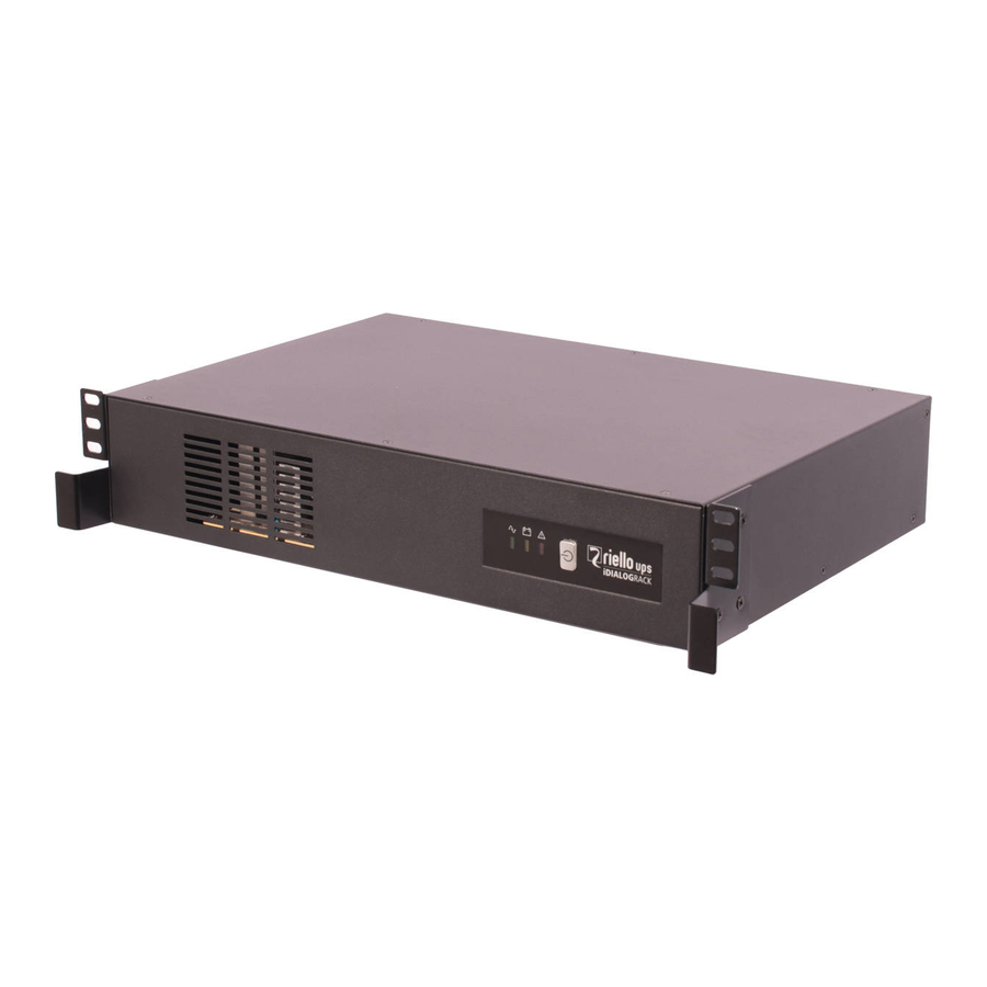
DESCRIPTION OF THE UPS
Front and rear views:
- Main STAND-BY/ON switch
![]() /GREEN LED: the UPS operates from the mains power supply
/GREEN LED: the UPS operates from the mains power supply![]() /YELLOW LED: the UPS operates on battery
/YELLOW LED: the UPS operates on battery![warning]() /RED LED: various messages (see the "Alarms and Report Signals table")
/RED LED: various messages (see the "Alarms and Report Signals table")- Input plug
- Circuit breaker
- IEC 10A output socket
- SCHUKO 10A output socket
- USB communication port
- Communication port RS232
- Remote Emergency Power Off (R.E.P.O.)
 /GREEN LED: the UPS operates from the mains power supply
 /YELLOW LED: the UPS operates on battery
INSTALLATION
Opening of packing and verification of its contents
Remove the UPS from its packaging and check that there is no visible damage caused during shipping. If there is any noticeable damage to the UPS, pack the product up and return to where it was purchased.
Packing contents
- UPS
- User manual
- Download card
- Warranty card
- Handles kit for rack installation
Positioning
Follow the instructions below to correctly install and position the UPS:
- The UPS must be placed on a horizontal surface.
- The UPS must not be exposed to direct sunlight.
- Ensure that the ambient temperature is between 0°C and 40°C, for optimal performance use at a maximum temperature of 25°C.
- The ambient humidity is less than 90%.
- Avoid dusty environments.
- Place the UPS at least 5cm from a wall to ensure adequate ventilation.
- Ensure that the UPS or any other heavy object is clear of the power supply cable.
- Ensure that the cables connecting loads to the UPS are not longer than 10metres.
Storage
The UPS must be fully recharged if it is to be stored for a long time. A full discharge and charge cycle should be carried out every 6 months to keep the battery in good condition.
OPERATION
Connection to mains and battery charging
Please ensure that the mains power supply to be used with this UPS has upstream protection rated at either 10A.
- Connect the UPS to the electrical mains through the input SCHUKO plug (5).
- The UPS will recharge its battery each time it is connected to a mains power supply (even if it is powered down). We recommend that the UPS is charged for 6-8 hours before connecting the loads.
Connecting the loads
After having loaded the UPS, loads can be connected (e.g.: computer, monitor, etc.) to the output sockets, these sockets are only powered when the UPS is on. Should mains power fail, the back-up sockets are battery-powered.
N.B.: we recommend not running laser printers or laser print devices from back-up sockets (7-8) together with other computer peripheral equipment. On odd occasions, this equipment uses a greater quantity of energy than when at rest. This set-up may lead to UPS overload and cause all equipment connected to be switched off.
Starting up/Shutting down
Press the main STAND-BY/ON switch to start-up the UPS and power the loads. Press the switch again to shut down the UPS and power down from the loads.
Starting up on battery (Cold start)
If there is no mains power supply present, pressing the main power switch will cause the UPS to start up using its battery as a source of power.
:
when starting up on battery, the output frequency is set to 50Hz.
USB port
The UPS can be connected to a computer for remote monitoring and sh tions using a USB cable. The UPS management software and related manual can be from www.rielloups.com.
RS232 serial port
The RS232 serial interface allows connection of the UPS to a PC (COM interface) by means of a pinto-pin serial cable with a maximum length of 3 meters, for the same functions of monitoring and shutdown, to the USB port.
:
If the RS232 communication port is used, it is not possible to communicate with the USB port and vice versa.
R.E.P.O.
The remote control terminal allows for implementation of the REPO function (Remote Emergency Power Off).
The UPS is provided by the manufacturer with the REPO terminals short-circuited. For installation remove the short circuit and connect to the device's normally closed contact.
In case of an emergency, if the stop device is used, the REPO control is opened and the UPS goes into stand-by mode and the load is completely disconnected.
:
before restarting the UPS, reset the stop device.
The circuitry of the remote control terminal board is self-powered with SELV circuits. Therefore, an external voltage supply is not required. When a contact is closed, a maximum current of 15mA circulates.
All connections with the remote control terminal board are made through a cable which guarantees a double insulation connection.
ALARMS AND REPORT SIGNALS
| Description | Switch position (1) | Led functioning | Other report signals | ||
Green led  | Yellow led  | Red led  | |||
| Stand-by | STAND-BY | Blinking | |||
| Operation on mains power | ON | Steady | |||
| Operation on battery | ON | Blinking | Slow blinking acoustic signal | ||
| End of discharge warning | ON | Blinking | Blinking acoustic signal | ||
| Overload | ON | Blinking | Blinking acoustic signal | ||
| Battery fault | ON | Steady | Steady | Blinking acoustic signal (10 seconds) | |
| Alarm or fault (other than overload) | ON | Steady | Continuous acoustic signal | ||
| R.E.P.O. contact open | STAND-BY / ON | Steady | |||
TROUBLESHOOTING
| PROBLEM | POSSIBLE CAUSE | PROCEDURE |
The UPS does not switch on | The UPS is switched off | Check that the STAND-BY/ON switch is in the ON position |
| The UPS input thermal protection device has been triggered | Disconnect non-essential equipment from the UPS. Reset the protection (6) by depressing the button. If the switch resets, start up the UPS and reconnect the equipment one device at a time. If the protection activates again, one of the connected devices is causing an overload condition. | |
| REPO connector open | Opening due to an emergency. If unwanted, check the status of any emergency devices. | |
| The UPS is working on battery even though mains power is available | The UPS input thermal protection device has been triggered | Disconnect non essential equipment from the UPS. Reset the protection (6) by depressing the button. |
| The mains power supply socket the UPS is connected to is not supplying power to the device | Connect the UPS to another mains power supply socket or have the mains supply checked by a qualified electrician. | |
| When there is a mains power supply failure, the UPS does not work for the expected runtime | The UPS battery is not sufficiently charged as there was not enough time for it to recharge after a recent power failure | Wait for the battery to recharge. It recharges each time the UPS is connected to a mains socket. It usually takes 8 hours for the battery to recharge fully. UPS operation time is a function of how charged the battery is. |
| The battery needs to be replaced. | Battery needs replacement. Contact the Service. | |
The red LED (4) flashes. | The UPS is overloaded. | Disconnect the backup outlet (7), the nonessential equipment, such as the printer, and connect to a separate power outlet. |
| The red LED (4) remains fixed and the acoustic signal is active | The UPS has a fault. | Remove the external devices from the UPS. Turn off the UPS and disconnect it from the mains. Connect the UPS to the mains and turn on again. If the UPS message the anomaly again, contact your authorized service centre. |
Battery fault message. | Battery fault. | Replace the battery. |
The UPS is not communicating with a PC. | The software sends a message that communication has been lost. | Check that the USB cable or the serial cable (for the models provided with serial ports) is connected to both the UPS and the PC and that the communication configuration of the software selected the correct communicarion port. |
| The software is not installed | Install the specific software for your computer's operating system. |
TECHNICAL DATA
| MODEL | 600VA | 1200VA | |
| INPUT | Voltage | 230Vac +20% / -25% | |
| Frequency | 50 or 60Hz +/-5% (with auto-sensing) | ||
| OUTPUT | Voltage (from battery) | 230Vac +/-10% (Pseudo-sinusoidal wave) | |
| Frequency (from battery) | 50 or 60Hz +/-1Hz (with auto-sensing) | ||
| Trigger time | 2-6 ms typical | ||
| Rated power VA | 600 | 1200 | |
| Rated power W | 360 | 720 | |
| PROTECTION DEVICES AND FILTERS | Overload and shortcircuit protection | From mains: overload input protection. From mains: automatic shutdown after 5 minutes with load >110% and immediate shutdown with load >120% or for shortcircuit. From battery: automatic shutdown after 5 seconds with load >110% and immediate shutdown with load >120% or for shortcircuit. | |
| BATTERY | Type | Sealed lead batteries, maintenance-free | |
| Typical recharge time | 6-8 hours | ||
| Protection | Protection against total discharge, battery replacement indicator | ||
| AMBIENT CONDITIONS | Operating conditions | Max altitude 1000m, 0-90% non condensing humidity, 0- 40°C | |
| VARIOUS | Noise | <40dB (at 1m from source) | |
| Earth leakage current | <1mA | ||
RPS SpA - Riello Power Solutions
Viale Europa, 7
37045 Legnago (VR)
Italy

Documents / Resources
References
Download manual
Here you can download full pdf version of manual, it may contain additional safety instructions, warranty information, FCC rules, etc.
Download Riello iDialog Rack 600 -1200 VA, 600VA, 1200VA Manual
Advertisement


Need help?
Do you have a question about the iDialog Rack and is the answer not in the manual?
Questions and answers