Table of Contents
Advertisement
Quick Links
Advertisement
Table of Contents

Related Manuals for Riello UPS MHT-FC UL Series


Summary of Contents for Riello UPS MHT-FC UL Series
- Page 1 125 to 200 kVA 480V 60Hz / 400-230V 50Hz three-Phase Output MHT-FC UL USER MANUAL Pag. 1 a 55 0MLMFCM13RUENUA...
- Page 2 RPS SpA Viale Europa 7 37045 Legnago (VR) Italy www.riello-ups.com Pag. 2 a 55 0MLMFCM13RUENUA...
- Page 3 Thank you for choosing our product. RPS S.p.A. is highly specialized in the development and production of Frequency Converters (FC). The FC’s of this series are high quality products, carefully designed and manufactured to ensure optimum performance. Applicability This manual applies to the following models of Frequency Converters: MHT FC 125 UL P, MHT FC 125 UL P TCE, 125 kVA / 112,5 kW, 480 V, 60Hz input 3P 3W - 400-230 V, 50Hz output 3P 4W MHT FC 160 UL P, MHT FC 160 UL P TCE,...
- Page 4 WARNING To reduce the risk of fire or electric shock, install this Frequency Converter in a temperature and humidity controlled, indoor environment, free of conductive contaminants. Do not operate near water or excessive humidity (95% maximum). Input and output over-current protection and disconnect switches must be provided by others. High ground leakage current may be present.
- Page 5 DEFINITION OF “OPERATOR” AND “SPECIALIZED TECHNICIAN” The professional figure responsible for accessing the equipment for ordinary maintenance purposes is defined with the term operator. This definition covers personnel that know the operating and maintenance procedures for the equipment, and that have been: Trained to operate in accordance with the safety standards relating to the dangers that may arise where electrical voltage is present.
- Page 6 PERSONAL PROTECTIVE EQUIPMENT No maintenance operations must be carried out on the device without wearing the Personal Protective Equipment (PPE) described below. Personnel involved in the installation or maintenance of the equipment must not wear clothes with wide sleeves or laces, belts, bracelets or other items that may be dangerous, especially if they are metallic.
-
Page 7: Table Of Contents
CONTENTS TCE ..................9 AYOUT UNIT WITHOUT TCE ..................10 AYOUT UNIT WITH ..................11 RELIMINARY OPERATIONS Removing the packaging and positioning the device................... 11 Storage ................................11 Handling................................11 ................. 12 NSTALLATION ENVIRONMENT Ambient conditions: ............................12 Dimensions of the premises ..........................12 Cooling of the premises ............................ - Page 8 1.1.25.6 Cyclic battery recharging ......................39 1.1.25.7 Two- level recharging ......................40 1.1.25.8 PRE-ALARM ......................... 40 1.1.25.9 AUTO-OFF Timer........................42 1.1.25.10 Modem set-up ......................... 42 1.1.25.11 "dial /send " modem ........................ 43 1.1.25.12 RS232 ............................43 1.1.25.13 Echo ............................44 1.1.25.14 Ident ............................
-
Page 9: Layout Unit Without Tce
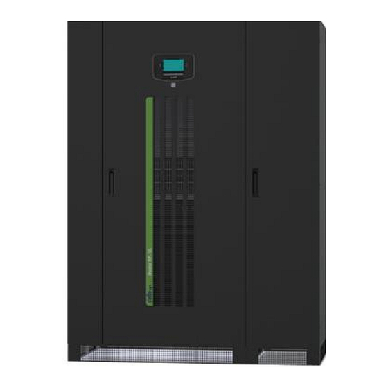
Layout unit without TCE Figure 1- Cabinet without TCE front view A Control panel with graphic display Door handle Ventilation grilles Communication area Front Cover panel with ventilation grilles Switch cover panel G Door SWIN: Input power switch SWOUT: Static switch output Pag. -
Page 10: Layout Unit With Tce
Layout unit with TCE Figure 2 - - Cabinet with TCE front view A Control panel with graphic display B Door handle C Ventilation grilles D Communication area E Front Cover panel with ventilation grilles F Switch cover panel G Door SWIN: Input power switch SWOUT: Static switch output Pag. -
Page 11: Preliminary Operations
Preliminary operations Removing the packaging and positioning the device On delivery, the packaging must be inspected to ensure that it is whole and that it has not been crushed or dented. Check in particular that neither of the two impact resistant devices on the packaging is red; if one of them is red; follow the instructions on the packaging. -
Page 12: Installation Environment
When being moved the cabinet should be handled with care; shocks or drops can damage it. Once in position, remove the packaging carefully in order not to scratch the device. The packaging should be removed as follows: Cut the bands Slide away the carton from above. -
Page 13: Cooling Of The Premises
Cooling of the premises The recommended operating temperature for the lifetime of the Frequency Converter (FC) and of the batteries is between 20 and 25°C. The lifespan of the battery depends on the operating temperature; with an operating temperature increase from 20°C to 30°C, the lifespan of the batteries is halved. -
Page 14: Electrical Connections
Electrical Connections Accessing the FC terminals Danger The following operations must be performed while the FC is disconnected from the utility mains power, switched off and all the input and output power switches on the equipment are open. Before performing connection, open all the input and output power switches and check that the FC is completely isolated from all power sources: battery and AC power line. -
Page 15: Fc -Single Module Configuration
FC -single module configuration The FC is designed to work as Single input Unit. Figure 3- Block schematic of Frequency Converter Pag. 15 a 55 0MLMFCM13RUENUA... -
Page 16: Cable Entry
1.1.1 Cable Entry The cables can enter in the FC from the bottom or from the top with the optional Top Cable Entry cabinet Proceed as follows to open the FC • Open the door • Remove the switch cover panel •... - Page 17 REAR Input Output battery cables entry Aux cables FC bottom closed entry FRONT Figure 5 - - Bottom cable entry footprint – with TCE Pag. 17 a 55 0MLMFCM13RUENUA...
-
Page 18: Connection Of Power Cables - Models Mht Fc Ul (P)
Connection of Power Cables – models MHT FC UL (P) 1.1.2 Connect the input, output and battery cables to the terminals as shown in the figure below: + Battery Output N Output Input Ground A-B-C A-B-C Figure 6- MHT FC 125, 160, 200 - Power connection to field terminals Note: For the Input, Output and Battery connections, respect the order from the top to bottom, or right to left, as described. -
Page 19: Connection Of Power Cables - Models Mht Fc Ul (P) Tce
1.1.3 Connection of Power Cables – models MHT FC UL (P) TCE Connect the input, output and battery cables to the terminals as shown in the figure below: Neutral OUTPUT BATTERY BATTERY PHASE A - OUTPUT PHASE B - OUTPUT PHASE C - OUTPUT PHASE A - INPUT PHASE B - INPUT... -
Page 20: Differential (Gfi)
1.1.4 Differential (GFI) If the FC protection against electric shock uses a differential current device (Ground Fault Interrupter), it must have the following characteristics: Operating threshold 300mA Class A or B (DC and rectified AC) Insensitive to transient current pulses Delay ≥... - Page 21 To access the interface cards, open the door and remove the protection panel secured with screws (K) as shown in the drawing: REF. DESCRIPTION PARALLEL EPO (Emergency Power Off control) REMOTE COMMANDS AND ALARMS RS232-2 RS232-1 SLOT 2 (aux) SLOT 1 (main) REMOTE ALARMS #1(optional) REMOTE ALARMS #2(optional) MODEM (optional) or MULTI I/O (optional)
- Page 22 Table 1- Aux signals isolation boards Connector J1 of Aux signals isolation board NAME TYPE FUNCTION AUX SWBATT INPUT Dry contact (NO) used to indicate when SWBATT is closed AUX SWBATT RETURN INPUT AUX SWMB INPUT Dry contact (NC) used to indicate when the SWMB EXT is closed AUX SWMB RETURN INPUT...
-
Page 23: Remote Commands, Alarms And Epo
1.1.7 Remote commands, alarms and EPO The card is equipped with a 14 positions terminal board. SELV CIRCUIT PROVIDED. CONNECT TO SELV CIRCUIT ONLY. POWER SUPPLY 1 power supply 12Vdc 80mA (max.) [pins 10 and 11]; ALARMS 3 FORM C dry contacts for alarms (rating 30 V AC / DC, 1 A); COMMAND 1 command programmable by panel [pins 11 and 12];... -
Page 24: Rs232
1.1.8 RS232 SELV CIRCUIT PROVIDED. CONNECT TO SELV CIRCUIT ONLY. (2) DB9 connectors are available for RS232 connection. The factory-set transmission protocol is as following: Baud rate Parity Data bits Stop bit 9600 Length cable (meters) Baud rate 9600 4800 2400 1200 Note: The BAUD RATE range [1200 –... -
Page 25: Slot 1 And Slot 2
1.1.9 SLOT 1 and SLOT 2 tollowing cards may be inserted (optional): NetMan (on SLOT 1 main or SLOT 2 aux) SELV CIRCUIT PROVIDED. CONNECT TO SELV CIRCUIT ONLY. Device for management of the FC’s on the Ethernet. It can send information on the status of the device with different protocols: Type Description... -
Page 26: Remote Alarms (Optional Cards)
1.1.10 Remote alarms (optional cards) SELV CIRCUIT PROVIDED. CONNECT TO SELV CIRCUIT ONLY. 6 output (relays): Form C dry contacts for alarms, rating 30 VAC/DC, 1A max, (programmable by display panel), 2 inputs (programmable by display panel) and 1x12V DC 100mA max auxiliary input. 1.1.11 Modem (optional) Model compatible with the communication standards between the FC and the software provided. -
Page 27: Start-Up
1.1.16 Start-up 1.1.16.1 Before starting up procedure • Check all the input/output terminals are securely tightened; • Check all the fuse holders have the fuse inserted, and are in the closed position; • Check the ground conductor is connected (yellow/green cable); •... -
Page 28: Control Panel And Display
Control Panel and Display Signal panel functions Figure 13- Control panel and display F1, F2, F3, F4, F5, F6, F7, F8 = FUNCTION KEYS. The function of each key is shown at the bottom of the display and it varies according to the menu. = Emergency Power Off button. - Page 29 Table 4- Led status indicators Led status indicators Indicator Symbol Color Function State Meaning N.A. NOT USED N.A. N.A. Mains is present and correct Mains Green line Flashing Mains is present but not correct indicator Mains is not present Load on battery Battery “LOW VOLTAGE ON BATTERY PRE-ALARM"...
-
Page 30: Graphic Display
Graphic display A wide graphic display is present on the FC door, which allows the user to have a close-up, detailed overview in real time of the status of the FC. The user can switch the FC on and off, check electrical mains, output, battery measurements etc. - Page 31 Table 5- Diagram item shapes diagram items shapes Active Inactive Meaning Input converter Output inverter Bypass line switch Battery Manual bypass line switch Bypass line input switch Battery switch Output switch Main line input switch Output load (40%VA or 0%VA) Battery (70%Ah or 0%Ah) Table 6- keys numbers and icons keys numbers and Icons...
-
Page 32: Basic Menu (Text Lines Area)
1.1.19 Basic menu (text lines area) If no commands have been inserted, the first text line shows messages to inform about status of operation. First text line NORMAL OPERATION U1100A OUT=100%VA, BATT=100%Ah, 5=ON Second text line In each operating condition, the display returns to the "basic menu" after two minutes from the last command inserted with the keys. -
Page 33: Language Setting Menu (Keys 1, 1)
100%VA provided in the example is obtained with the measurement of the output current. The number indicates the output current in percentage of the rated value. The percentage value showed is the greater of the rms and peak current between the three phases. BATT= 100%Ah example of the percentage of the capacity of battery recharge. -
Page 34: Measurements Menus (Key 2)
1.1.23 Measurements menus (key 2) The measurements with two line displayed, are selected from the basic menu by pressing key 2 IN=100,100,100%V; 101,101,101%A; 60.1Hz OUT= 230,230,230Vln(400V);100,100,100%A 100,100,100%W 50.1Hz;147,147,147%Ap BAT=xxxV; +0.0A; i=230,230,230Vln;yyyVdc OUT= 1000 BATT= 10000sec nBATT= 1000; n0%Ah= 100; 2007-01-01 Ts=28,Tr=50,Ti=49,Tb=25;... -
Page 35: Full Page Measurements And Output Waveforms (Key 2,7)
1.1.24 Full page Measurements and output waveforms (key 2,7) The full-page measurements and output voltage and current waveform are selected by pressing key 7 from the two line measurement menu. Basic Menu IN=100,100,100%V; 101,101,101%A; 60.1Hz BY=277,277,277Vln (480V); 60.1Hz; 125kVA 277V 3L 60Hz [15:35:55] _________________________________ [[1;... -
Page 36: Controls Menu (Key 3)
1.1.25 Controls Menu (key 3), Menu 3, 2 BATTERY TEST Keys 8 and 7 to increase/decrease the contrast DISPLAY CONTRAST: 6 ADJUSTMENT: 7=-, 8=+ 2=BATTERY TEST 4=DISPLAY CONTRAST Code ? ………………. Menu 3, 5 5=PERSONALIZ. 6=BYPASS 7=TOTAL BLOCK TOTAL BLOCK Menu 3, 7 1.1.25.1 Keys menu 3, 2: battery test... -
Page 37: Customizing
1.1.25.2 Customizing The "CUSTOMIZING" menu is accessed by means of key 5 from the COMMANDS menu; an intermediate menu will then be displayed in which a CODE has to be entered. Access by CODE ensures that unauthorized persons cannot modify the operating parameters of the equipment. -
Page 38: Entering Customized Codes
1.1.25.3 Entering customized codes Keys menu 3, 5: CODE 436215 The code is no longer required for 2 minutes after it has previously been inserted. The next menu can only be accessed by inserting the correct code, otherwise it returns to the basic menu. Menu 3, 5, 436215, 2 RATED OUTPUT VOLTAGE BATTERY... -
Page 39: Battery
1.1.25.5 Battery Press the following sequence of keys to access the menu: o Press 3, o press 5, o Enter code 436215, o Then press 3 code present value set Battery: Type=1 Capacity=15Ah Adjustment: 2-/3+ 5/6=-/+10 7=-,8=+ Battery type modify values capacity On initial installation the rated capacity value of the connected battery must be inserted;... -
Page 40: Two- Level Recharging
1.1.25.7 Two- level recharging This type of recharging has two steps or two levels (EN 50272-2); the first step include fast charging (U1) with limited current, while in the second step charging is with float voltage (U2). NOTE: this type of recharging may be configured on site and is mainly used for special type batteries such as vented and Ni-Cd. - Page 41 Type “0” Battery With the battery set to type 0, the following menu is displayed: (420Vmin,480Vp,540Vs) Pre-alarm : 5min Adjustment: (4=setV), 7=-,8=+ When key 4 is pressed, the program proposes the setting of the three voltage values. Vbat.test: Vmin., Vp, Vs: 420, 480, 540V Adjustment: 3-4+, 5-6+, 7-8+ Preset value...
-
Page 42: Auto-Off Timer
1.1.25.9 AUTO-OFF Timer. Press the following sequence of keys to access the menu: o Press 3, o press 5, o Enter code 436215, o press 6 o then press 5 AUTO-OFF Timer: Toff >0: 0', Ton= 0: 0' ADJUSTMENT: (5=Toff, 6=Ton) 7=-, 8=+ Press key 1 to exit the menu. -
Page 43: Dial /Send " Modem
MODEM=0 NOTE: the configuration MODEM=0 is essential when the modem is not used, and the RS232 connector is used for connection to the remote panel 1= signal DTR is activated (terminal 20 at +12V), the modem is enabled to reply (it should be remembered that a remote panel connected to the RS232 connector in place of the modem remains off). -
Page 44: Echo
1.1.25.13 Echo Press the following sequence of keys to access the menu: o Press 3, o press 5, o Enter code 436215, o press 7 o then press 6 Press key 1 to exit the menu. Keys 7 and 8 are used to decrease/increase the number used to enable the "ECHO" function. The number may vary from 0 to 1 to disable or enable the function. -
Page 45: Recorded Voltages Measurements
Key 6: activates submenu 4, 6 " RECORDED CODES" and allows the exchange of stored alarm message with the display of the corresponding status codes at the time of the stored event, and vice versa. The status codes allow a more in-depth analysis by the trained personnel. 1.1.26.1 Recorded voltages measurements Press the following sequence of keys to access the menu:... - Page 46 This key switch to the page showing the message and codes of 4 past events and it is possible to look to the other past events by arrow keys. s=8000 c=0000 b=0000 r=0000-08 i=0000-00 a=0000-0000 2011- 1-24/13:35: 0;n120 ------------------------------------------------------------ s=8000 c=0000 b=3C20 r=0000-08 i=0000-00 a=0400-0000 2011- 1-24/13: 5: 5;n119 ------------------------------------------------------------...
-
Page 47: Disabling The Audible Alarm (Key 5)
1.1.27 Disabling the audible alarm (key 5) Press the following sequence of keys to access the menu: 5 During operation from the basic menu, the operator can permanently disable or re-enable the audible alarm (buzzer) by pressing key 5. "5=ON" is shown in the basic menu when the audible alarm is enabled and "5=OFF" when the audible alarm is disabled. -
Page 48: Maintenance
Maintenance The Frequency Converter is designed and produced to last a long time, even in the most harsh conditions. It should be remembered however that this is electronic power equipment, which requires periodic maintenance. Moreover, some components have a limited lifespan and as such must be periodically checked and replaced: in particular the batteries, the fans and in some cases the electrolytic capacitors. -
Page 49: General Characteristics
General characteristics 200 kVA FC models MFC sizes 125 kVA 160 kVA MECHANICAL DATA Width (inches [mm]) 39.40 [1000] Depth / height (inches [mm]) 33.46 [850] / 74.80 [1900] Ventilation Forced Leakage current (max) 300mA Noise at 1m from front (0÷100% load) (dBA) Applicable Standards UL Standard 1778 5... - Page 50 200 kVA FC models MFC sizes 125 kVA 160 kVA INVERTER Rated power PF=0.9 (kVA) lag Active power PF=1 (kW) 112.5 Power derating (kVA/kW) for PF =0.8/0.9 lead 0.85/0.89 Rated voltage 400Vac 3-phase + N Rated frequency 50Hz Voltage range adjustment +5% -10% Voltage variation [Static] ±...
-
Page 51: Rated Currents
Rated currents WARNINGS To reduce the risk of fire, connect only to a circuit provided with branch circuit protection with maximum current rating per the table, below, in accordance with the National Electrical Code, ANSI/NFPA 70. Use at least 75°C rated copper wire. Minimum wire size is based on full load ratings applied to NEC Code Table 310-16. -
Page 52: Appendixa Alarm Messages
Torque specifications Bolt size Torque load 5/16 10 lbf-ft 13.5 Nm 22 lbf-ft 30 Nm 37 lbf-ft 50 Nm Appendix A Alarm messages Below is a list of the alarm messages that are shown on the first line of the display panel, the “A=” column shows the number that is also displayed on the right in the lower row. - Page 53 Indicates that a signal of “insulation loss” has been received from an external device INSULATION LOSS Indicates that the sequence of the phases at the bypass line input is not correct. INPUT VOLTAGE SEQUENCE It is normally sufficient to switch any two phases over in order to obtain normal NOT OK operation.
- Page 54 INSULATION LOSS The external optional ac imput insulation checking device, detected the ac. insulation A.C. lossing. INSULATION LOSS The external optional dc output insulation checking device, detected the ac. insulation D.C. lossing. Motor Generator parallel mode Optional operation (rem.com)" NOT USED Inverters OFF The inverters are commanded to be OFF from an external command Pag.
-
Page 55: Appendixb - Optional Remote Commands
Appendix B - Optional remote commands Technical support personnel may modify the COMMAND that can executed from the standard “INV.OFF” remote input or from the optional remote input/output card. COMMAND Name Description Typical application Disables the recharging of the battery, keeping the When there is a generator, this Battery charge recharge current to a minimum, independently of the...
Need help?
Do you have a question about the MHT-FC UL Series and is the answer not in the manual?
Questions and answers