
Related Manuals for Riello UPS MASTER HP


Summary of Contents for Riello UPS MASTER HP
- Page 1 UNINTERRUPTIBLE POWER SUPPLY MASTER HP - UL 55 – 100Ah BATTERY CABINET User Manual...
- Page 2 RPS SpA Viale Europa 7 37045 Legnago (VR) Italy www.riello‐ups.com 0ML190480RUENUC page 2 / 24 ...
-
Page 3: Table Of Contents
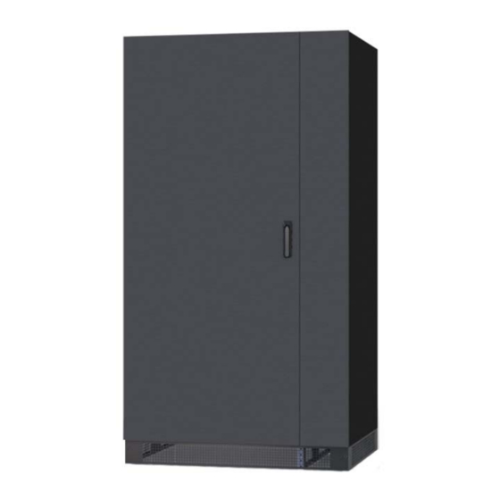
TABLE OF CONTENTS SECTION 1 ..................... 3 INTRODUCTION ................................ 3 SECTION 2 ..................... 5 SAFETY WARNINGS ..............................5 SECTION 3 ..................... 8 BATTERY CABINET SETUP ........................... 8 FLOOR LOAD‐CARRYING CAPACITY ........................ 8 CLEARANCE ................................8 HANDLING THE CABINET (unloading and transporting) ............... 8 INSPECTING THE EQUIPMENT ........................ 1 0 ... - Page 4 This manual is intended to describe all steps for installing the battery cabinet, starting from the empty Fig. 1 - BBX battery cabinet external dimensions cabinet as it is presented without battery blocks installed. This manual cover the versions. BBX 1900 480V UL L6 3U : 55 Ah Rated Voltage 480Vdc (240 cells 40x 12Vdc blocks) OCP 200 A (Circuit breacker provided ).
-
Page 5: Section 1
SECTION 2 SAFETY WARNINGS IMPORTANT SAFETY INSTRUCTIONS SAVE THESE INSTRUCTIONS This manual contains important instructions that you should follow during installation and maintenance of the Battery Cabinet. Please read all instructions before operating the equipment and save this manual for future reference. - Page 6 DANGER This equipment contains HIGH VOLTAGE can cause personal injury or death. All repairs and service should be performed by AUTHORIZED SERVICE PERSONNEL ONLY. There are NO USER SERVICEABLE PARTS inside the Battery Cabinet. WARNING This equipment contains its own energy source (batteries). Hazardous voltage may be present even when the battery cabinet is not connected to a power source.
- Page 7 The life expectancy of batteries is temperature dependence at which they are stored and operated. Batteries should be used in a 70 F (21 C) environment. Consider that for every 15 F (8.3 C) increase in temperature, the life expectancy is halved. Exposure to temperatures in excess of 90 F (32 C) should be limited to no more than 30 days per year.
-
Page 8: Section 3
SECTION 3 BATTERY CABINET SETUP This section describes: Floor load-carrying capacity and clearances Handling the cabinet Equipment inspection FLOOR LOAD-CARRYING CAPACITY When planning the commissioning, consider the battery cabinet weight for floor where it will be placed. The load-carrying capacity of the installation surface must be adequate for point and distributed loading. The approximate weights are shown in the following table. - Page 9 2) Remove N.6 10mm lag bolts securing the cabinet to the pallet. (N.3 for side see Fig. 2). 3) See Fig. 3 to identify the correct area for the insertion of the forks. 4) Make sure forks are at maximum separation 5) Keep the people out of the area of possible fall of the cabinet, during unloading and through path of destination.
-
Page 10: Inspecting The Equipment
INSPECTING THE EQUIPMENT If Battery cabinet is not provided with battery blocks installed: Remove all panels (front, rear, left and right side). See in the figure the appearance of the cabinet without panels. The components used for the assembly of battery blocks are always provided and you’ll find the followings inside the cabinet: Pos.# 1) Cable 1/0 or #2x1/0 AWG length 360mm (14.17 in.) crimped to “green”... -
Page 11: Section 4
SECTION 4 INSTALLATION AND ASSEMBLY OF BATTERY BLOCKS The following operations must be performed by properly trained and qualified personnel, within a suitable area with no access to other people WARNING! When all the cells are connected, the voltage to the terminals could exceed 500Vdc and it is dangerous. Risk of electric shock or burns due to accidental short circuits Appropriate eye protection must be worn to prevent injuries from accidental electrical arcs Risk of electrolyte leakage from batteries. -
Page 12: Remove Trays
REMOVE TRAYS 1. To facilitate the assembly operations, all the trays, except the number 1, can be removed and assembled out of cabinet 2. Remove the tray block, on both sides, remove the screws as shown in Fig. 5; on each block is stamped the number referred to tray (see Fig. -
Page 13: Tray Assembly Procedure
TRAY ASSEMBLY PROCEDURE Place n. 8 batteries on the tray positioned as shown in Fig. 7-7bis Tighten each row of batteries using the straps provided (pos. 14) as shown in Fig. 7-7bis Connect the busbars provided (pos. 7÷10) as shown in Fig. 8 (see the number stamped on each bars). Put the insulating sheet provided on the assembled tray for covering bare bus bars and terminals, Fix the insulating sheet with cables ties, Fig. - Page 14 Fig. 7bis – 55Ah Fig. 7 ‐ 100Ah tray Part. Fig. 8 ‐ bus bars references Fig. 9 ‐ battery tray assembled Fig. 10 – Insulating sheet fixed with cable ties for covering bare bars of batteries 0ML190480RUENUC page 14 / 24 ...
-
Page 15: Connection Between The Trays
Fig. 12‐ battery tray positioned by forkift Fig. 11‐ detail of fastening CONNECTION BETWEEN THE TRAYS Make sure battery circuit breaker is open before operating TO DESCRIPTION FROM TRAY 1 TRAY 2 Connect each other the grey (or green) connectors TRAY 1 CIRCUIT BREAKER Connect the blue connectors TRAY 2 TRAY 3 Connect grey (or green) connectors TRAY 3 CIRCUIT BREAKER Connect the red connectors TRAY 4 CIRCUIT BREAKER Connect the blue connectors TRAY 4 TRAY 5 Connect the grey (or green) connectors TRAY 5 CIRCUIT BREAKER Connect the red connectors ... - Page 16 Fig. 13‐ Battery cabinet assembled Color table connectors Colors Abbreviation Blue BL Red RD Gray GY Green GN When the Battery Cabinet is full assembled reinstall all panels 0ML190480RUENUC page 16 / 24 ...
- Page 17 0ML190480RUENUC page 17 / 24 ...
- Page 18 ELECTRICAL DRAWING 0ML190480RUENUC page 18 / 24 ...
-
Page 19: Section 5
SECTION 5 CONNECTION TO UPS SYSTEM The ground terminal of battery cabinet must be connected with ground terminal of UPS cabinet. NEC article 250 for identify grounding system and sizing grounding conductors POWER CABLE CONNECTION Table 4 ‐ sizing conductor battery battery cabinet OCP device * Field wiring bolt size torque Model ... - Page 20 0ML190480RUENUC page 20 / 24 ...
- Page 21 0ML190480RUENUC page 21 / 24 ...
-
Page 22: Auxiliary Cables Connections (Option)
AUXILIARY CABLES CONNECTIONS (OPTION) The signals described in this paragraph are not part of safety circuit, since they are not insulated from dangerous voltage. Do not connect to SELV circuit Connect to UPS only using the cables provided (600V minimum rating). Circuit breaker interface 1) If opening of Battery Circuit Breaker is required for EPO (Emergency Power Off) operation, Terminals SWBAT COIL must be connected to terminals SWBAT COIL of UPS cabinet. - Page 23 Fig. 14‐ battery cabinet terminal block detail 0ML190480RUENUC page 23 / 24 ...
- Page 24 Fig. 15 ‐ Connections diagram of auxiliary signals 0ML190480RUENUC page 24 / 24 ...
Need help?
Do you have a question about the MASTER HP and is the answer not in the manual?
Questions and answers