
Related Manuals for Riello UPS Master-HP 160


Summary of Contents for Riello UPS Master-HP 160
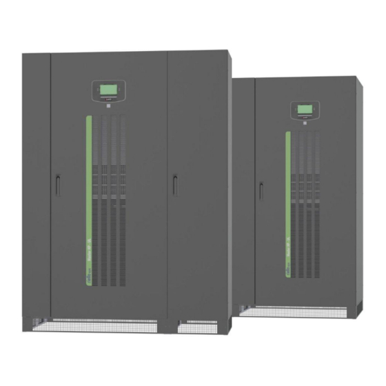
- Page 1 160 to 250 kVA Three-Phase Output MASTER HP-UL USER MANUAL...
- Page 2 RPS SpA Viale Europa 7 37045 Legnago (VR) Italy www.riello-ups.com page 2 / 85 0MLMHTM16RUENUB...
- Page 3 Applicability This manual applies to the following models: Master-HP 160 160 kVA, 480 V input, 480 V output, 60 Hz, configured as wye-wye or delta-delta (see below); “00” may be replaced with an alternate two character designator that denotes installed options as described in the order documentation.
- Page 4 DANGER This UPS contains LETHAL VOLTAGES. All repairs and service should be performed by AUTHORIZED SERVICE PERSONNEL ONLY. There are NO USER SERVICEABLE PARTS inside the UPS. WARNING To reduce the risk of fire or electric shock, install this UPS in a temperature and humidity controlled, indoor environment, free of conductive contaminants.
- Page 5 3. Must have a background of technical training, or specific training relating to the procedures for the safe use and maintenance of the equipment. Emergency interventions The following information is of a general nature. First aid interventions Company regulations and traditional procedures should be followed for any first aid intervention that may be required.
- Page 6 Personal Protective Equipment No maintenance operations must be carried out on the device without wearing the Personal Protective Equipment (PPE) described below. Personnel involved in the installation or maintenance of the equipment must not wear clothes with wide sleeves or laces, belts, bracelets or other items that may be dangerous, especially if they are metallic. Long hair must be tied in such a way as to ensure that it is not a hazard.
-
Page 7: Table Of Contents
CONTENTS ......................9 AYOUT ................11 RELIMINARY OPERATIONS Removing the packaging and positioning the UPS ............ 11 Storage ........................11 Handling ........................11 ..............12 NSTALLATION ENVIRONMENT Ambient conditions: ....................12 Dimensions of the premises ..................12 Cooling of the premises .................... 13 Ventilation for battery premises ................ - Page 8 1.1.19 Input ............................43 1.1.20 Ground Fault ..........................43 1.1.21 Emergency power off device (EPO) .....................44 1.1.22 External maintenance bypass......................44 4.15 Mains, and load connections..................44 1.1.23 UPS AC input / output power connection ..................44 1.1.24 Connecting the Parallel Card (Option) ..................45 4.16 Connection of signals ....................
-
Page 9: Layout
Layout MASTER HP – UL - F RONT A Control panel with graphic display Door handle Ventilation grilles D Communication area Front Cover panel with ventilation grilles Switch cover panel G Door SWIN: Input power switch SWBY: Static switch bypass input SWOUT: Static switch output 0MLMHTM16RUENUB page 9 / 85... - Page 10 MASTER HP – UL MBY TCE - F RONT Control panel with graphic display Door handle Ventilation grilles Communication area Front Cover panel with ventilation grilles Switch cover panel Door 1. SWIN: Input power switch 2. SWBY: Static switch bypass input 3.
-
Page 11: Preliminary Operations
Preliminary operations Removing the packaging and positioning the UPS On delivery, the packaging must be inspected to ensure that it is whole and that it has not been crushed or dented. Check in particular that neither of the two impact indicator devices on the packaging is red; if one of them is red;... -
Page 12: Installation Environment
When being moved the cabinet should be handled with care; shocks or drops can damage it. Once in position, remove the packaging carefully in order not to scratch the device. The packaging should be removed as follows: 1. Cut the bands 2. -
Page 13: Cooling Of The Premises
Cooling of the premises The recommended operating temperature for the lifetime of the UPS and of the batteries is from 20 to 25°C. The lifespan of the battery depends on the operating temperature; with a rise temperature of 10°C above 20°C , the lifespan of the batteries is halved. A heat dissipation system is required to keep the temperature of the premises where the units are placed within the range of 20-25°C. -
Page 14: Electrical Connections
Electrical Connections CCESSING THE TERMINALS The following operations must be performed while the UPS is disconnected from the utility mains power, switched off and all the input and output power switches on the equipment are open. Before performing connection, open all the input and output power switches and check that the UPS is completely isolated from all power sources: battery and AC power line. -
Page 15: Ups In Single Configuration
UPS in single configuration The UPS is designed to work as Single input Unit or as Dual input Unit. Schematic diagram: Single input Unit (*) SWMB only in MASTER HP – UL TCE version. Schematic diagram: Dual input Unit (*) SWMB only in MASTER HP – UL TCE version. 0MLMHTM16RUENUB page 15 / 85... -
Page 16: Cable Entry
1.1.1 Cable Entry The cables can enter in the UPS from the bottom in the MASTER HP – UL version, from the top or the bottom with the MASTER HP – UL MBY TCE version Proceed as follows in order to open the UPS ... - Page 17 MASTER HP – UL MBY TCE FRONT External Control Cable Entry Power AC Cable Entry Power Battery Cable Entry UPS Bottom - Cables can enter in the UPS from the top or from the bottom- 0MLMHTM16RUENUB page 17 / 85...
-
Page 18: Connection Of Power Cables For Single Input Unit
1.1.2 Connection of Power Cables for Single input Unit Connect the input, output and battery cables to the terminals as shown in the figure below: MASTER HP – UL Power connection Terminals Note: For the Input, Output and Battery connections, follow the order from the top to bottom, or right to left, as described in the boxes. - Page 19 MASTER HP – UL MBY TCE Power connection Terminals Note: For the Input, Output and Battery connections, follow the order from the top to bottom, or right to left, as described in the boxes. The label marked “N” present on the terminal identifies the neutral terminal. The single input is a factory default configuration.
-
Page 20: Connection Of Power Cables For Dual Input Unit
1.1.3 Connection of Power Cables for Dual input Unit Connect the input, output and battery cables to the terminals as shown in the figure below: MASTER HP – UL Power connection Terminals Remove the jumpers present between the SWIN and SWBY. The input phase connections attach using bolts through the holes that were previously used to attach the bus bars. - Page 21 MASTER HP – UL MBY TCE Power connection Terminals Remove the jumpers present between the BYPASS and INPUT bars. Note: For the Input, Output and Battery connections, follow the order from the top to bottom, or right to left, as described in the boxes.
-
Page 22: Minimum Wire Size Requirements
Minimum Wire Size Requirements Input (for single input unit) Phase and Neutral Conductor models 160 kVA 500 kcmil or 2x2/0 AWG 200 kVA 2x4/0 AWG 250 kVA 2x4/0 AWG Rectifier Input (for dual input unit only) Phase Conductor models 160 kVA 500 kcmil or 2x2/0 AWG 200 kVA 2x4/0 AWG... - Page 23 CAUTION: Use at least 75 C rated copper wire. Minimum wire size is based on full load ratings applied to NEC Code Table 310-16. Code may require a larger AWG size than shown in this table because of temperature, number of conductors in the conduit, or long service runs. Follow local requirements.
-
Page 24: External Overcurrent Protection Device And Terminals
External Overcurrent Protection device and terminals CAUTION to reduce the risk of fire, connect only to a circuit provided with branch circuit protection with maximum current rating per the table, below, in accordance with the National Electrical Code, ANSI/NFPA 70. Input (for single input unit) Nominal Maximum... -
Page 25: Differential (Gfi)
Battery Nominal Current Maximum Current OCP Device rating Bolt Size (in) models 160 kVA 316A@480Vdc 378A@400.8Vdc 400A 200 kVA 395A@480Vdc 473A@400.8Vdc 500A 250 kVA 493A@480Vdc 591A@400.8Vdc 600A CAUTION: Input and output circuit protection must be provided by others as part of the UPS installation. -
Page 26: Backfeed Protection
1.1.5 Backfeed protection The UPS is provided with a redundant device to prevent voltage backfeed on the input line due to an internal fault. This protection device works by switching off the inverter when detecting a fault current that cause voltage backfeed on the bypass line during operation from the inverter. -
Page 27: Mains, Load And Battery Connections
Mains, load and battery connections Input line without neutral A transformer must be inserted either on the mains supply line or on the bypass line (as shown in the drawings) if the load requires a neutral. Schematic diagram: Single power line without neutral from the source SWMB SWBY 3P+G... -
Page 28: Connection Of Signals And Remote Commands
Battery connections This UPS has been designed to be supplied by a battery consist on 240 Lead Acid Battery cells (40 12Vdc battery blocks). See “General Characteristics” for voltages and current of charge If “RIELLO BBX 1900 489V UL 3U” battery cabinets are used, the connection have to be made in accordance with the manual for the battery cabinet. - Page 29 MASTER HP – UL MBY TCE A- PARALLEL B- EPO (emergency power off control) C- REMOTE COMMANDS AND ALARMS D- RS232-2 E- RS232-1 F- SLOT 2 (aux) G- SLOT 1 (main) H- REMOTE ALARMS (optional) REMOTE ALARMS (optional) M- AUX SIGNALS ISOLATION BOARD N- TERMINAL BLOCK 0MLMHTM16RUENUB page 29 / 85...
- Page 30 NOTE: Aux signals isolation board allows receiving external auxiliary contacts and keeping them isolated from the UPS internal circuits making easy connections in case of paralleling of the units. Jumpers AUX (SWBATT, SWMB, SWOUT) must be connected to the terminal of the board if no external auxiliary contacts are presents.
-
Page 31: Parallel (Optional)
1.1.7 Parallel (optional) -A- To be used for the connection of UPS’s in a parallel configuration only. See the chapter “parallel version” on page 1.1.8 REMOTE COMMANDS, ALARMS AND EPO -C- The card is equipped with a 14 positions terminal board. SELV CIRCUIT PROVIDED. -
Page 32: Rs232
The position of the contacts as shown is without the alarm present. The contacts rating is 24Vac - 1A. Please refer to APPENDIX A for the list of alarms and commands that can be programmed. The change of function may be made by authorized technical support personnel. 1.1.9 RS232 SELV CIRCUIT PROVIDED. -
Page 33: Slots 2-1 , The Following Cards May Be Inserted (Optional)
Modem male female female male maschio femmina DB9 male RS232-1 femmina maschio - E - For connection with a modem use a cable RS232-2 standard. See the diagram for connection with a modem. Computer male female female male maschio femmina femmina maschio RS232-2... -
Page 34: 1.1.13 Swout And Swmb Aux
1.1.13 SWOUT and SWMB aux. -The auxiliary contacts of the external SWMB and of the SWOUT shall be connected to the board of each UPS in parallel, as depicted in the diagram below. Note: MASTER HP-UL series have input terminals (for acquiring the status of aux contacts) isolated from the internal circuits of the UPS. -
Page 35: Start-Up Procedure
Start-up procedure mains power supply The mains power supply has to be present in order to start up the UPS The UPS output terminals will be powered in this phase and all loads will be supplied. All users must therefore be warned before carrying out the start-up procedure. BATTERY CABINET ( if present): The battery cabinet must be provided with a disconnect device for connection to the UPS. -
Page 36: 1.1.14 Battery Operation Check
SWMB (only in MASTER HP – UL TCE version) The mechanical bypass switch SWMB must not be closed during normal operation of the UPS. SWMB should only be closed during UPS maintenance operations in order to keep the load powered (see the instructions on page 38). When the UPS is first started up, it is in on-line mode (see page 37 ). -
Page 37: 1.1.15 On - Line - Factory Setting
1.1.15 On - line - factory setting - Load is always powered by the inverter, in the event of an input mains outage the load continues to be powered from the inverter using the energy stored in the batteries. On – line: The load is always powered by the inverter, with steady voltage and frequency, using the energy from the mains power supply (INPUT). -
Page 38: Stabilizer (Operation In On-Line Mode Without Battery)
1.1.18 Stabilizer (operation in on-line mode without battery) Load is supplied by inverter, if there is a mains failure the load is not powered, the batteries are not present. Stabilizer: This mode of operation makes the UPS a power conditioner with no backup capability. The load is always powered through the inverter, with steady voltage and frequency, using the energy from the input mains. -
Page 39: Ups And Load Shutdown
Static bypass is an automatic electronically switched bypass path. It is engaged if the inverter is overloaded or if fails. Also, the static bypass is the normal source of the load if the UPS is in “Standby On” Mode or if it is in “Smart Active” Mode, with the inverter taking the load if the bypass source is out of range. -
Page 40: Block Diagram
4.11 Block diagram page 40 / 85 0MLMHTM16RUENUB... -
Page 41: Components Of The Block Diagrams
4.12 Components of the block diagrams The UPS is made up of the following sub-assemblies: IGBT RECTIFIER This represents the input stage and its function is to convert the AC voltage of the mains into DC voltage. Rectifier start-up can be programmed by the display panel. -
Page 42: Ups In Parallel Configuration (Option)
INVERTER This is the output stage, the function of which is to convert the DC voltage from the RECTIFIER or from the BATTERY into a steady sinusoidal AC voltage. The inverter output is isolated from the input and from the batteries by an isolation transformer. -
Page 43: Electrical System Set-Up
4.14 Electrical system set-up All the information contained in the section on electrical system set-up in relation to the UPS remains valid with the addition of the information set out below. 1.1.19 Input The instructions seen in the first part of the manual for a single UPS remain valid; each unit must be protected with equivalent fuses or switches. -
Page 44: Emergency Power Off Device (Epo)
1.1.21 Emergency power off device (EPO) When several devices are connected in parallel, the EPO command must be sent to all UPS’s simultaneously, as shown in the figure below: UPS 8 UPS 2 UPS 1 a - EPO terminal board on the UPS b- EPO switch with auxiliary contacts (not provided). -
Page 45: Connecting The Parallel Card (Option)
Phase connections Phase L1 of the mains source must be connected to input phase L1 on all the UPS’s; all the output phases L1 must be connected together and with phase L1 of the load. This rule must be observed for phases L2, L3 and for the input and output neutral. -
Page 46: Connection Of Signals
4.16 Connection of signals The signals of parallel UPS’s are connected in a closed loop configuration; if the loop is interrupted at any point, either due to a fault or for maintenance, operation of the system continues normally, as will be shown repeatedly below. The parallel UPS’s are connected through the “signals RJ45-flat- adapter”... - Page 47 - RJ45-flat-adapter signals parallel card. Note: The UPS may be provided with one of two versions of the parallel card which differ in the type of switch used (type 1 or type 2). The difference between the two switches is the position of the control lever. J1 RJ45 type connector J2 RJ45 type connector start position...
- Page 48 Two UPS’s in parallel UPS 1 UPS 2 LED (D) SW1 (E) START CONT Note: 2 RJ45 cables are required. System will not start up unless 2 cables are installed. UPS 2 UPS 1 page 48 / 85 0MLMHTM16RUENUB...
- Page 49 Three UPS in parallel UPS 1 UPS 2 UPS 3 LED (D) SW1 (E) START CONT CONT Note: 3 RJ45 cables are required. System will not start up unless 3 cables are installed. UPS 2 UPS 2 UPS 1 To add other parallel UPS’s, a “UPS PARALLEL CABLE” must be added for each new UPS connected. The signal connection must not be removed when one UPS is shut down 0MLMHTM16RUENUB page 49 / 85...
-
Page 50: Start-Up Procedure
4.17 Start-up procedure Before starting up the whole system for the first time, some checks have to be performed to see that the UPS’s are connected to each other correctly. A) Open all the switches and disconnects on the UPS’s (SWIN, SWOUT and SWMB if present) and SWBATT on the battery cabinets. -
Page 51: Operating Modes
4.18 Operating modes UPS units connected in parallel share the current load. In a system with UPS’s connected in parallel, there is a single MASTER unit and the remaining units are SLAVE. The UPS’s are same models and sizes and the MASTER is chosen on start-up. The MASTER unit is shown on the display panel by the capital letter “P”... - Page 52 Example of parallel operation For clarification reasons, the instructions below refer to a system with three UPS’s, but are valids for systems with more units. Let us assume that all signals cables are ok and not damaged and that the UPS’s are in the following state: UPS STATUS 1) Normal operation, Master unit 2) Normal operation, Slave unit...
-
Page 53: Mechanical Bypass (Only For Master Hp - Ul Ptce Version)
4.19 Mechanical Bypass (only for MASTER HP – UL PTCE version) Follows the precautions when operating SWMB SWMB must not be closed on a UPS that is off and connected in parallel with other units operating normally. This operation may cause a fault on the UPS’s which may create a dangerous voltage at the output. - Page 54 Procedure b) The bypass line is out of the range; the following message is shown on display panel: BAD BYPASS VOLTAGE or SWBY OFF and the green LED 1 will flash 1. Open all the switches on the UPS (SWIN, SWOUT, SWBY and the battery cabinet circuit breaker/disconnect).
- Page 55 With hot removal, it is not necessary to shut down all the UPSs of the system in order to remove one. A) UPS parallel cable type RJ45 UPS 1 UPS 3 UPS 2 B) RJ45 female/RJ45 female shielded adaptor cable UPS BYPASS CABLE NOTE: if the UPS to be removed has SW1 in the start position, one...
-
Page 56: Signal Panel Functions
Signal panel functions Control Panel View 250kVA LED Bypass line indicator LED Mains line indicator LED Battery powering the load LED Load on bypass LED Normal output LED Alarm for internal fault Graphic display F1, F2, F3, F4, F5, F6, F7, F8 = FUNCTION KEYS. The function of each key is shown at the bottom of the display and it change according to the menu. - Page 57 EPO = Emergency Power Off button. Led status indicators Indica Symbol Color Function State Meaning Input Bypass line is present and correct Bypass Green line Flashing Input Bypass line is present but not correct indicator Input Bypass line is not present Mains is present and correct Mains Green...
- Page 58 RAPHIC DISPLAY A wide graphic display is present on the UPS door, which allows the user to have a mimic detailed overview in real time of the status of the UPS. The user can switch the UPS on and off, consult electrical mains, output, battery measurements etc.
- Page 59 Picture of the UPS display having all items OFF, 250kVA Table of diagram items Shapes Active Inactive Meaning Input converter Output inverter Bypass line switch Battery Manual bypass line switch Bypass line input switch Battery switch Output switch Main line input switch Output load (40%VA or 0%VA) Battery(70%Ah or 0%Ah) Table with keys numbers and Icons...
- Page 60 Basic menu (text lines area) If no commands have been inserted, the first text line shows messages to inform about status of operation. First text line NORMAL OPERATION U200A OUT=100%VA, BATT=100%Ah, 5=ON Second text line In each operating condition, the display returns to the "basic menu" after two minutes from the last command inserted by keys.
-
Page 61: Language Setting Menu (Keys 1, 1)
The message OUT changes to BY when the load is not powered from the inverter (normal operation) but from the mains through the bypass line. The message OUT=100%VA changes to OUT= SWMB when the load is powered through the mechanical bypass switch, and the output current cannot be provided. -
Page 62: Measurements Menus (Key 2)
1.1.26 Measurements menus (key 2) The measurements with two line displayed, are selected from the basic menu by pressing key 2 IN=100,100,100%V, 60.2Hz OUT=277,277,277Vln Measurement of the three voltages, neutral phase and input Measurement of the three output phase voltages of frequency. -
Page 63: Full Page Measurements And Output Waveforms (Key 2, 7)
1.1.28 Full page Measurements and output waveforms (key 2, 7) The full page measurements and output voltage and current waveform are selected by pressing key 7 from the two line measurement menu. Basic Menu IN=100,100,100%V; 101,101,101%A; 60.1Hz BY=277,277,277Vln (480V); 60.1Hz; 250kVA 125kVA 277V 3L 60Hz [15:35:55]... -
Page 64: Controls Menu (Key 3)
1.1.29 Controls Menu (key 3), BATTERY TEST Menu 3, 2 Keys 8 and 7 to increase and DISPLAY CONTRAST: 6 ADJUSTMENT: 7=-, 8=+ decrease the contrast. Code ? ………………. 2=BATTERY TEST 4=DISPLAY CONTRAST Menu 3, 5 5=PERSONALIZ. 6=BYPASS 7=TOTAL BLOCK Menu 3, 6 INVERTER OFF/BYPASS Menu 3, 7... -
Page 65: Customizing
1.1.29.2 CUSTOMIZING The "CUSTOMIZING" menu is accessed by means of key 5 from the COMMANDS menu; an intermediate menu will then be displayed in which a CODE has to be entered. Access by CODE ensures that unauthorized persons cannot modify the operating parameters of the equipment. -
Page 66: Rated Output Voltage
1.1.29.4 RATED OUTPUT VOLTAGE. Press the following sequence of keys to access the menu: 3, 5, 436215, 2 Keys 7 and 8 can be used to decrease or increase the rated output voltage. The value displayed is the voltage between phase and neutral "Vln". The value set modifies the operation of the inverter, during normal operation. -
Page 67: Pre-Alarm
NOTE: this type of recharging may be configured on site and is mainly used for special type batteries such as open vase and NiCd. For batteries of type 1, 2 or 3, press key 2 from menu a to change from cyclical charge to charging at two levels float voltage Ac= xxx, Vbat.: min=xxx, ch xxx, max=xxx Bat.type(1) 2=Cycl.->ON ,... - Page 68 Type “0” Battery With the battery set to type 0, the following menu is displayed: (420Vmin,480Vp,540Vs) Prealarm : 5min Adjustment: (4=setV), 7=-,8=+ When key 4 is pressed, the program proposes the setting of the three voltage values. Vbat.test: Vmin., Vp, Vs: 420, 480, 540V Adjustment: 3-4+, 5-6+, 7-8+ Preset value...
-
Page 69: Auto-Off "Va
1.1.29.7 AUTO-OFF "VA" Press the following sequence of keys to access the menu: 3, 5, 436215, 6: Automatic Switch-OFF when Output < 0%VA Adjustment: (5=Toff,Ton) 7=-,8=+ Press key 1 to exit the menu. Keys 7 and 8 can be used to decrease or increase the percentage threshold of the output load for the AUTO-OFF function and switching the system to the bypass line;... -
Page 70: Bypass Voltage Range Adjustment
The "end of discharge pre-alarm" contact for remote alarms is also switched. In this case the system remains active for the next 4 minutes, after that the system switches onto the bypass line and then deactivates. There is no output voltage after deactivation. The interval between the start of the alarm and deactivation is equal to the interval selected as PRE-ALARM. -
Page 71: Dial /Send" Modem
NOTE: for correct operation, use a modem pre- configured which admit "HAYES" type commands and that is able to dial the telephone number using pulses or tones depending on the telephone line to be used. Example of messages sent to the modem in the event of an "INTERNAL FAULT 5" alarm. Assuming that the settings are as follows: Modem =2, Dial=23456, Send=123456. -
Page 72: Ident
1.1.29.15 IDENT. Press the following sequence of keys to access the menu: 3, 5, 436215, 7, 7: Press key 1 to exit the menu. Keys 7 and 8 can be used to decrease or increase the number used for the identification of a single unit in systems with several UPS connected to a single RS232 serial line. -
Page 73: Total Block
1.1.29.19 TOTAL BLOCK Press the following sequence of keys to access the menu: 3, 7 : Total System Shut-OFF Command = 47263 WARNING, the Output Voltage will be OFF Exit the menu by pressing key 8 or any other key with a sequence other than the one described here. Pressing keys 4, 7, 2, 6, 3 in succession as shown on the display activates the command for TOTAL BLOCK of the system. -
Page 74: Recorded Value On Full Page
The "RECORDED CODES" menu is accessed with key 6 from menu 4 "RECORDED EVENTS" and menus 4, 2; 4, 2, 2; 4,2,2,2 that is, the recorded measurement menus. Return to the basic menu by means of key 1. Apart from key 6, the other keys have the same functions as those described for menu 4, and the messages on the lower line also remain the same. -
Page 75: Disabling The Audible Alarm (Key 5)
1.1.31 DISABLING THE AUDIBLE ALARM (key 5) Press the following sequence of keys to access the menu: 5 During operation from the basic menu, the operator can permanently disable or re-enable the audible alarm (buzzer) by pressing key 5. "5=ON" is shown in the basic menu when the audible alarm is enabled and "5=OFF" when the audible alarm is disabled. -
Page 76: Maintenance
Maintenance The uninterruptible power system is designed and produced to last a long time, even in the most severe conditions. It should be remembered however that this is an electronic power equipment, which requires periodic maintenance. Moreover, some components have a limited lifetime and they must be periodically checked and replaced: in particular the batteries, the fans and in some cases the electrolytic capacitors. -
Page 77: General Characteristics
General characteristics 160kVA UPS models 200kVA 250kVA MECHANICAL DATA Width (inches [mm]) 39.4 [1000] Width (inches [mm]) TCE version * 55 [1400] Depth / height (inches [mm]) 33.46 [850] / 74.80 [1900] Ventilation Forced Noise at 1m from front (0÷100% load) (dBA) UL Standard 1778 5 edition... - Page 78 UPS models 160kVA 200kVA 250kVA INTERMEDIATE D.C. CIRCUIT N. cells (Lead acid batteries) 240 (40 12Vdc battery) Rated battery voltage Float charge (20°C) with cyclical charge not active Battery type 1 or 2 542 (2,26V/cells-default) 528 (2,2 V/cells-default) 2÷2,5 V/cells programmable Boost charge Battery type 1 or 2 562 (2,34 V/cells - default)
- Page 79 UPS models 160kVA 200kVA 250kVA INVERTER Rated power Pf 0.9 (kVA) inductive Active power Pf 1 (kW) Rated power reduction factor (kVA/kW) 0.85/0.89 for Pf =0.8/0.9 capacitive Rated voltage 480Vac 3-phase + N Rated frequency 60Hz Rated voltage adjustment field +5% -10% Static variation ±...
- Page 80 UPS models 160kVA 200kVA 250kVA BYPASS Rated voltage 480Vac 3-phase + N Rated voltage tolerance ± 15% (adjustable from ± 10% to ± 25% from control panel) Rated frequency 60Hz Frequency tolerance ± 2% ( adjustable up to ± 6% from control panel) Switching onto bypass with synchronized Inverter (UPS in “Normal ~ 0ms...
-
Page 81: Appendixa Alarm Messages
Appendix A Alarm messages Below is a list of the alarm messages that are shown on the first line of the display panel, the “A=” column shows the number that is also displayed on the right in the lower row . ALARMS EVENT MESSAGE DESCRIPTION... - Page 82 Alarm present when the system has been deactivated and switched onto the BYPASS COMMAND bypass, by means of a specific command inserted via the keyboard. The command ACTIVE; 8=COMMAND remains stored also during shutdown due to a mains power supply failure. The system does not return to normal operation when the mains power supply is restored if the block has been set intentionally and not deactivated.
- Page 83 Parallel Redund. lost: Redund. In a parallel system, the redundancy is has been lost because the operating units unit OFF are less than t he set number of units. Brake circuit fail The optional brake circuit has a failure Brake circuit Overload The optional brake circuit has an overload Rectifier switched OFF by The input converter stage is switched off by a remote command.
-
Page 84: Appendixb - Optional Remote Commands
Appendix B - Optional remote commands Technical support personnel may modify the COMMAND that can executed from the standard “INV.OFF” remote input or from the optional remote input/output card. COMMAND Name Description Typical application Disables the recharging of the battery, keeping the When there is a generator, this allows Battery charge recharge current to a minimum, independently of the... - Page 85 UPS conform to: This device has been designed and manufactured in accordance with the standards for the product. -Safety: EN 62040-1 - Electromagnetic Compatibility: EN 62040-2(cat. C3) - Methods of specifying the performance and test requirements: EN 62040-3 The conformity to these norms allow to put the mark.
Need help?
Do you have a question about the Master-HP 160 and is the answer not in the manual?
Questions and answers