Table of Contents
Advertisement
Advertisement
Table of Contents

Related Manuals for Riello UPS Sentinel Dual SDU 4000


Summary of Contents for Riello UPS Sentinel Dual SDU 4000
- Page 3 NTRODUCTION Congratulations on purchasing a UPS Sentinel Dual product and welcome to Riello UPS! To use the support service offered by Riello UPS, visit the site www.riello-ups.com Our Company is a specialist in the design, development and manufacturing of uninterruptible power supplies (UPS).
-
Page 4: Table Of Contents
NDICE PRESENTATION UPS V IEWS RONT ISPLAY PANEL VIEW ATTERY OPTIONAL INSTALLATION NITIAL CONTENT CHECK NSTALLATION ENVIRONMENT OWER VERSION OWER VERSION WITH ATTERY ACK VERSION OWER ONNECTION NTERNAL ROTECTIVE EVICES OF THE XTERNAL ROTECTIVE EVICES ONNECTION CABLES CROSS SECTION DETAILS ONNECTIONS ATTERY NSTALLATION... - Page 5 ONITORING AND CONTROL SOFTWARE ONFIGURATION SOFTWARE CONFIGURATION OMMUNICATION PORTS RS232 CONNECTOR OMMUNICATION TROUBLESHOOTING LARM CODES AULT TECHNICAL DATA - 5 -...
-
Page 6: Presentation
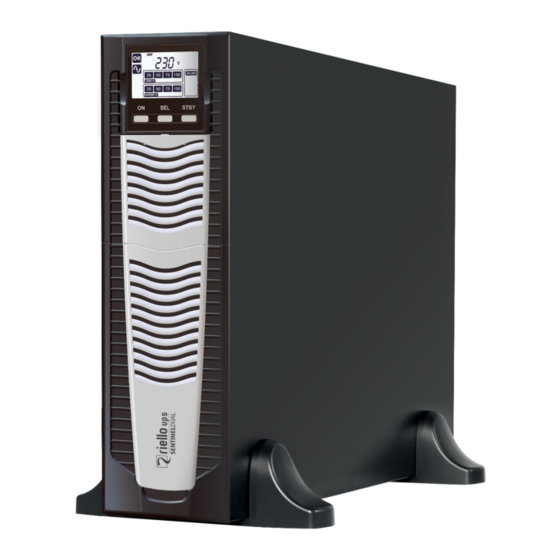
PRESENTATION SENTINEL DUAL Sentinel Dual is the best solution for powering mission critical applications and electro-medical devices requiring maximum power reliability. Flexibility of installation and use (digital display, user-replaceable battery set), as well as the many communication options available, makes the Sentinel Dual suitable for many different applications from IT to security. SENTINEL DUAL can be installed as Tower (floor standing) or Rack, ideal for network and server rack applications. -
Page 7: Ups Views
UPS V IEWS RONT With front panel Without front panel Extractable/rotatable display plate 1/0 Switch Release slits Battery pack connector Removable front panel Battery pack retention panel - 7 -... -
Page 8: Rear View
Battery expansion connector RS232 communication port EnergyShare sockets (10A max) and overcurrent Cooling fan protection Communication Card Slot IEC sockets (16A max) and overcurrent protection Remote control terminal Protection box for IN/OUT connection USB communication port - 8 -... -
Page 9: Display Panel View
ISPLAY PANEL VIEW “SEL” button Load level indicator “ON” button Configuration area “STAND-BY” button Maintenance request Regular operation Timer Mains operation Measurement display area Battery operation Stand-by / alarm Load powered by bypass EnergyShare Battery charge indicator - 9 -... -
Page 10: Battery Box ( Optional )
ATTERY OPTIONAL The BATTERY BOX, with the same dimensions and aesthetic appearance of the UPS, is optional. The BATTERY BOX contains batteries which allow the operating time of the uninterruptible power supplies to be increased during extended blackouts. The number of batteries contained can vary according to the type of UPS for which the BATTERY BOX is intended. -
Page 11: Installation
INSTALLATION NITIAL CONTENT CHECK After opening the packaging, it is first necessary to check the contents. The package must contain: UPS (and eventual BATTERY BOX) Safety manual + Quick start guide + Download card USB cable Support feet + extensions Handles for rack installation Handle screws Connection cable UPS - Battery Box... -
Page 12: Installation Environment
NSTALLATION ENVIRONMENT The UPS and the Battery Box must be installed in ventilated, clean environments which are sheltered from bad weather. The relative humidity in the environment must not exceed the maximum values shown in the Technical Data table. The ambient temperature, whilst the UPS is in operation, must remain between 0 and 40°C, and the UPS must not be positioned in places which are exposed to direct sunlight or to hot air. -
Page 13: Tower Version
OWER VERSION This chapter describes the steps for preparing the UPS and Battery Box for tower version use. BEFORE CARRING OUT THE FOLLOWING SEQUENCE OF OPERATIONS, ENSURE THAT: THE UPS IS COMPLETELY SWITCHED OFF AND NOT CONNECTED TO THE MAINS POWER SUPPLY OR TO ANY LOAD. -
Page 14: Tower Version With Battery Box
OWER VERSION WITH ATTERY BEFORE CARRING OUT THE FOLLOWING SEQUENCE OF OPERATIONS, ENSURE THAT: THE UPS IS COMPLETELY SWITCHED OFF AND NOT CONNECTED TO THE MAINS POWER SUPPLY OR TO ANY LOAD. THE BATTERY BOX IS DISCONNECTED FROM THE UPS, FROM ANY OTHER BATTERY BOXES AND WITH THE BATTERY ISOLATOR OPEN ... -
Page 15: Rack Version
ACK VERSION The sequence of operations to be followed in order to transform the UPS or Battery Box into rack version are described below. BEFORE CARRING OUT THE FOLLOWING SEQUENCE OF OPERATIONS, ENSURE THAT: THE UPS IS COMPLETELY SWITCHED OFF AND NOT CONNECTED TO THE MAINS POWER SUPPLY OR TO ANY LOAD. -
Page 16: Power Connection
OWER ONNECTION ALL OPERATIONS DESCRIBED IN THIS SECTION MUST BE PERFORMED BY QUALIFIED PERSONNEL ONLY. Our Company assumes no liability for damages caused by incorrect connections or operations not contained in this manual. The UPS has HAZARDOUS electrical voltages inside it, even when the input and/or battery switches are off. -
Page 17: External Protective Devices
XTERNAL ROTECTIVE EVICES LINE PROTECTION: MAGNETOTHERMAL OR FUSE Within the UPS there are protection devices for output and internal faults. You must protect the input line with the appropriate protection devices. These devices must comply with the regulations of the country where the UPS is installed. -
Page 18: Battery Box Installation
ATTERY NSTALLATION ATTENTION: CONFIRM ON THE SPECIFICATION LABEL THAT THE VOLTAGE FROM THE BATTERY BOX IS THE SAME AS THAT ALLOWED BY THE UPS. THE CONNECTION BETWEEN THE UPS AND THE BATTERY BOX MUST BE MADE WITH THE BATTERY BOX FUSE HOLDERS OPEN. CONNECT THE CABLE BETWEEN THE UPS AND BATTERY BOX. -
Page 19: Use
ONNECTIONS AND SWITCHING ON FOR THE FIRST TIME 1) Power ON the UPS. 2) Press the 1/0 switch located under the removable front panel. 3) After a few moments, the UPS will switch on, the display will light up, there will be a beep and the icon will start to flash. -
Page 20: Display Panel Messages
ISPLAY PANEL MESSAGES This chapter describes, in detail, the various information that can be displayed on the LCD. STATUS MESSAGES ICON STATUS DESCRIPTION Fixed Indicates a fault Flashing The UPS is in stand-by mode Fixed Indicates regular operation Fixed The UPS is operating from the mains The UPS is operating from the mains, but the output voltage is not Flashing synchronised with the mains voltage... -
Page 21: Measurement Display Area
EASUREMENT DISPLAY AREA The front panel can be used to display important UPS operating information. When the UPS is switched-on, the display shows the main voltage value. To display a different measurement, press the “SEL” button repeatedly until the desired measurement appears. In the event of a fault/alarm (FAULT) or a lock (LOCK), the display will automatically show the type and code of the corresponding alarm. -
Page 22: Operating Mode Configuration
PERATING ODE CONFIGURATION The area of the display shown in the figure displays the active operating mode and allows the user to choose other modes directly from the display panel. HOW TO PROCEED: To access the configuration area, hold down the “SEL” button for at least 3 seconds till the “SET” icon lights up. ... - Page 23 PROGRAMMABLE AUXILIARY SOCKETS (EnergyShare) The EnergyShare sockets are outlets that allow for the automatic disconnection of the load applied to them in certain operating conditions. The events that determine automatic disconnection of the EnergyShare sockets can be selected by the user through the configuration software.
-
Page 24: Battery Pack Replacement
ATTERY PACK REPLACEMENT The UPS is also equipped with a dedicated battery pack that allows for easy replacement of batteries (hot swap) in complete safety, thanks to the protected connection system. WHEN THE BATTERY PACK IS DISCONNECTED, THE LOADS CONNECTED TO THE UPS ARE NOT PROTECTED IN THE EVENT OF A MAINS FAILURE ... - Page 25 Remove the battery pack's retention panel carrying out the operations shown in the figure below. Slip off the battery pack pulling it towards the outside, as shown in the figure below. Be careful when extracting and lifting up the battery pack as it is heavy. ATTENTION: the new battery pack must contain the same number and type of batteries (see the label located on the battery pack near the connector).
-
Page 26: Software
OFTWARE CAUTION: If the RS232 communication port is used, it is not possible to communicate with the USB port and vice versa. It is advisable to use a cable which is shorter than 3 metres for communication with the UPS. To obtain additional communication ports with different functions, independent from the standard USB and RS232 ports on the UPS, various accessories are available which can be inserted into the communication card slot. -
Page 27: Ups Configuration
CONFIGURATION The table below illustrates all the possible configurations available to the user in order to best adapt the UPS for individual requirements. It is possible to perform these operations using the configuration software. FUNCTION DESCRIPTION DEFAULT POSSIBLE CONFIGURATIONS 50 Hz Output nominal Selects the rated output ... - Page 28 FUNCTION DESCRIPTION DEFAULT POSSIBLE CONFIGURATIONS Selects the permitted Low: 180 ÷ 200 in 1V steps Bypass voltage Low: 180V voltage range for switching thresholds High: 264V High: 250 ÷ 264 in 1V steps to the bypass Bypass voltage Selects the permitted ...
-
Page 29: C Ommunication Ports
OMMUNICATION PORTS On the back of the UPS (see UPS Views), the following communication ports are present: RS232 connector USB connector Expansion slot for additional communication cards RS232 CONNECTOR RS232 CONNECTOR PIN # SEGNALE NOTE Programmable OUTPUT #3 *: [default: UPS in lock] (*) Opto-isolated contact max. -
Page 30: Troubleshooting
TROUBLESHOOTING An irregular operation of the UPS is frequently not due to malfunctions, but to simple problems, inconveniences or distractions. Therefore, the user is advised to consult the table below providing useful information on how to solve the most common problems. - Page 31 PROBLEMA POSSIBILE CAUSA SOLUZIONE THE DISPLAY SHOWS THE Switch off and disconnect the UPS from the power INPUT RELAY FAULTY CODES: L10, L11, F11 supply and contact the support centre. THE DISPLAY SHOWS THE CONTROL CARD IS NOT Switch off and disconnect the UPS from the power CODE: L02 INSERTED CORRECTLY supply and contact the support centre.
-
Page 32: A Larm Codes
LARM CODES Using a sophisticated self-diagnosis system, the UPS is able to check its own status and any anomalies and/or faults which may occur during normal operation and display them on the display panel. If there is a problem, the UPS signals the event by showing the code and the type of active alarm on the display (FAULT and/or LOCK). - Page 33 LOCK alerts are normally preceded by an alarm signal and their scale leads to the power-off of the inverter and the load being powered by the bypass line (this procedure is excluded for locks due to serious, persistent overloads and short circuits). CODICE DESCRIZIONE Control card is not inserted correctly...
-
Page 34: Technical Data
TECHNICAL DATA INPUT Nominal voltage [Vac] 220 - 230 - 240 (1W+N+PE) Maximum operating voltage [Vac] Nominal frequency [Hz] 50 - 60 Nominal current 18.5 BATTERY Recharge time < 4h for 80% of the load Nominal voltage [Vdc] OUTPUT Nominal voltage [Vac] Selectable: 220 / 230 / 240 Frequency...
Need help?
Do you have a question about the Sentinel Dual SDU 4000 and is the answer not in the manual?
Questions and answers