Table of Contents
Advertisement
Quick Links
Advertisement
Table of Contents
Troubleshooting

Related Manuals for Neptune L900


Summary of Contents for Neptune L900
- Page 1 Certification Exhibit FCC ID: P2SL900M IC: 4171B-L900M FCC Rule Part: 15.247 ISED Canada Radio Standards Specification: RSS-247 Project Number: 72126503 Manufacturer: Neptune Technology Group Inc. Model: L900M Manual 5015 B.U. Bowman Drive Buford, GA 30518 USA...
- Page 2 L900™ MIU Pit Installation and Maintenance Guide...
- Page 4 L900™ MIU Pit Installation and Maintenance Guide...
- Page 5 Copyright This manual is an unpublished work and contains the trade secrets and confidential information of Neptune Technology Group Inc., which are not to be divulged to third parties and may not be reproduced or transmitted in whole or part, in any form or by any means, electronic or mechanical for any purpose, without the express written permission of Neptune Technology Group Inc.
- Page 6 Professional Installation In accordance with section 15.203 of the FCC rules and regulations, the L900 MIU must be professionally installed by trained utility meter installers. Industry Canada (IC) Statements: Section 8.4 of RSS-GEN...
- Page 7 Type (s) d'antenne approuvé R900 Pit antennaaximum L900™ MIU Pit Installation Neptune Technology Group Inc. andMaintenance Guide 1600 Alabama Highway 229 Literature No. IM L900 Pit MIU 09.17 Tallassee, AL 36078 Part No. 13381-001 Tel: (800) 633-8754 Fax: (334) 283-7293 Copyright © 2017 Neptune Technology Group Inc.
-
Page 8: Table Of Contents
Verifying/Preparing the Encoder Register Installation of a Register (Non Pre-Wired or Potted Only) Chapter 4: Pit Installation Prior to Installation Storage Unpacking Tools and Materials Site Selection L900 MIU Pit Installation Installing the Antenna L900 MIU Pit Installation and Maintenance Guide... - Page 9 Contents Begin the Installation Threading the F-Connector Installing the Scotchloks Connecting the Splice Tube Tying the Cable and Magnet Swiping the L900 MIU Testing the Installation Chapter 5: Data Logging Extraction About Data Logging Accessing Data Logging Initializing the Data Logger...
- Page 10 Figures Figure 1 – L900 MIU - Pit Figure 2 – L900 MIU - Pit Dimensions - Front Figure 3 – L900 MIU Pit Dimensions - Side Figure 4 – L900 MIU Pit Antenna Figure 5 – Wiring a Neptune Encoder Register Figure 6 –...
- Page 11 Figures Figure 31 – L900 MIU Attached to Antenna Figure 32 – Magnet Swipe the L900 MIU Figure 33 – HHU Home Screen Figure 34 – N_SIGHT Main Screen Figure 35 – Data Logger Options Figure 36 – Reader ID Input Figure 37 –...
- Page 12 Tables Table 1 – Supported Encoder Maximum Cable Length Table 2 – L900 MIU Pit Environmental Conditions Table 3 – L900 MIU Pit Functional Specification Table 4 – L900 MIU Pit Functional Specification Table 5 – Recommended Tools Table 6 – Recommended Materials Table 7 –...
- Page 13 Tables This page intentionally left blank. L900 MIU Pit Installation and Maintenance Guide...
-
Page 14: Chapter 1: Product Description
15-minute intervals and transmits a mobile message that includes the meter reading data and the unique nine-digit L900 MIU ID every 20 seconds. This allows the meter to be read by an HHU or mobile data collection unit. -
Page 15: Product Description
The fixed network message that transmits for use on a LoRa network is sent every three hours. The L900 MIU is designed to offer advantages to utility organizations of all sizes: Increases meter reading accuracy. Eliminates infrastructure concerns and the burden of managing collection devices. -
Page 16: Chapter 2: L900 Specifications
Chapter 2: L900 Specifications This chapter provides you with the specifications for the L900 MIU. Electrical Specifications The power is supplied by a Lithium battery. Transmitter Specifications This section provides information on transmitter specifications. ® Transmit Period Every 20 seconds - R900... -
Page 17: Specifications - L900 Miu Pit
Register Reading Eight digits L900 MIU ID Nine digits Dimensions and Weight This section provides the dimensions and weight of the L900 MIU. Table 4 – L900 MIU Pit Functional Specification Dimensions Refer to Figure 3 and Figure 4 Weight 1.0 lbs. -
Page 18: Figure 2 - L900 Miu - Pit Dimensions - Front
Chapter 2: L900 Specifications Figure 2 – L900 MIU - Pit Dimensions - Front Figure 3 – L900 MIU Pit Dimensions - Side L900 MIU Pit Installation and Maintenance Guide... -
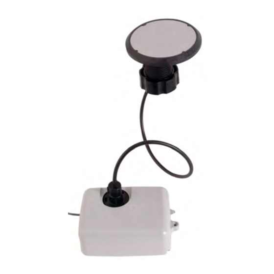
Page 19: Figure 4 - L900 Miu Pit Antenna
Chapter 2: L900 Specifications Figure 4 – L900 MIU Pit Antenna L900 MIU Pit Installation and Maintenance Guide... -
Page 20: Chapter 3: General Installation Guidelines
Tools and Materials Table 5 below and Table 6 on the next page show the recommended tools and materials you need to successfully install the L900 MIU. It is possible that some items do not apply to your specific installation, or the list does not contain all required tools or materials. -
Page 21: Safety And Preliminary Checks
Notify the customer of your presence and tell them you need access to the water meter. Write in the ID number(s) of the L900 MIU you are about to install, if the site work order does not have an L900 MIU ID number. -
Page 22: Installation Of A Register (Non Pre-Wired Or Potted Only)
AutoDetect ProRead register must be programmed for three- wire mode. If connecting the L900 MIU to a new ProRead encoder register, or if a three-conductor cable is already connected to a ProRead encoder register, ensure that the ProRead register is programmed for three-wire mode using the ProRead programmer and its RF/L900 MIU 6, 8, or 10 ID TDI format. -
Page 23: Figure 5 - Wiring A Neptune Encoder Register
Chapter 3: General Installation Guidelines Figure 5 – Wiring a Neptune Encoder Register Figure 6 – L900 MIU Color Code for Wires 6. If required, connect the three conductor wires to the encoder register's terminal per the manufacturer's instructions. See Figure 5 and Figure 6. -
Page 24: Figure 7 - Cable Threaded Around Strain Relief Posts
Figure 7 – Cable Threaded Around Strain Relief Posts 8. Apply sealant liberally and ensure that it encapsulates the terminal screws and exposed wires. See Figure 8. Neptune requires Novaguard G661 sealant or Dow Corning compound 4. Figure 8 – Application of the Sealant Any leak point can cause a reading failure in a submerged meter setting. -
Page 25: Figure 9 - Covering The Terminal Screws
9. Snap the cover onto the encoder register. See Figure 9 below. Figure 9 – Covering the Terminal Screws 10. Run the cable to the L900 MIUand fasten it securely. Do not exceed maximum cable lengths as defined in Table 1 on page 4. -
Page 26: Chapter 4: Pit Installation
After the inspection is complete, store the cartons in a clean, dry environment. Keep in mind that the L900 MIU has an internal battery. Storage for more than one year can affect product life. Be sure to use a first-in first-out inventory control system. -
Page 27: Tools And Materials
Chapter 4: Pit Installation Tools and Materials Table 5 on page 7 and Table 6 on page 8 show the recommended tools and materials you need to successfully install the L900 MIU. Some items may not apply to your specific installation, or the list may not contain all required tools or materials. -
Page 28: L900 Miu Pit Installation
Although the L900 MIU has a cable already attached (2 feet or 6 feet), some installations can require additional cable. In these cases, the maximum cable length between the encoder register and L900 MIU depends on the register's manufacturer and model. -
Page 29: Installing The Antenna
Chapter 4: Pit Installation Select a location for the L900 MIU that meets the recommendations in "Site Selection" on page 14. Installing the Antenna 1. Insert the antenna cable and housing through the 1¾- inch hole in the meter pit lid. See Figure 13. -
Page 30: Begin The Installation
Figure 16 shows a completed installation of the antenna. Figure 16 – Installation Completed Begin the Installation Complete the following steps to install the L900 MIU in a pit. 1. Remove black plastic thread protector cap from the male F-connector on the L900 MIU. -
Page 31: Threading The F-Connector
3. Apply a coating of Novaguard around the base of the F-connector and on the flat rubber washer. See Figure 4. Using a torque wrench, connect the coaxial cable connector to the F-connector on the L900 MIU/housing, tightening it to 15 inch-pounds. Figure 19 – Apply Novaguard Antenna connection should have Novaguard applied inside the connector. -
Page 32: Installing The Scotchloks
Complete the following steps to install the Scotchloks. 1. Complete steps outlined in "L900 MIU Pit Installation" on page 15 to install the L900 MIU through the lid. 2. Use 3M Scotchloks type UR connector to connect the L900 MIU wires to the encoder wires. -
Page 33: Figure 25 - Ur Crimping Tool
Figure 27. 10. After all three color wires have been connected, go to "Testing the Installation" on page 1 to ensure proper connections and the L900 MIU is functioning properly. Figure 27 – Three Color Wires Connected L900 MIU Pit Installation and Maintenance Guide... -
Page 34: Connecting The Splice Tube
2. Separate each gray wire and place in the slots on each side as shown in Figure 29. Figure 29 – Gray Wire in Slots 3. Snap cover closed to finish the installation as shown in Figure 30. Figure 30 – Cover in Place L900 MIU Pit Installation and Maintenance Guide... -
Page 35: Tying The Cable And Magnet Swiping The L900 Miu
Be careful not to lodge the L900 MIU between the meter box and any components inside the box. Make sure the L900 MIU is placed in such a way that it does not lodge itself when the pit lid is removed. -
Page 36: Testing The Installation
Chapter 4: Pit Installation Testing the Installation If the L900 MIU is connected to an E-CODER register or another register with an eight-digit output, the L900 MIU will transmit an eight-digit read. For example, read 12345678 (E-CODER or other eight-digit register output). - Page 37 Chapter 4: Pit Installation This page intentionally left blank. L900 MIU Pit Installation and Maintenance Guide...
-
Page 38: Chapter 5: Data Logging Extraction
HHU connected to the R900 BCT via Bluetooth. The activation signal is sent by the R900 BCT to the L900 MIU which in turn sends the data intervals to the R900 BCT and are saved in the HHU. -
Page 39: Figure 34 - N_Sight Main Screen
2. From the HHU Menu screen, click UTILS (option 4). See Figure 34. Figure 34 – N_SIGHT Main Screen 3. Click DATA LOGGER (option 9). See Figure 35. Figure 35 – Data Logger Options L900 MIU Pit Installation and Maintenance Guide... -
Page 40: Initializing The Data Logger
1. Verify the time is correct, and click YES. See Figure 37. Figure 37 – HHU Time Confirmation The HHU must be synchronized prior to data logging in order to set the clock. L900 MIU Pit Installation and Maintenance Guide... -
Page 41: Figure 38 - Initialize Rf Device
Figure 38 – Initialize RF Device You must initialize the R900 BCT each time you attempt to data log. 3. Select RF and type the L900 MIU ID. See Figure 39. Figure 39 – L900 MIU ID Entry L900 MIU Pit Installation and Maintenance Guide... -
Page 42: Figure 40 - Capture Button
Chapter 5: Data Logging Extraction You can type the L900 MIU ID with the number pad keys or expand the on-screen keyboard. 4. After you type the L900 MIU ID, click CAPTURE. See Figure 40. Figure 40 – Capture Button 5. -
Page 43: Initiating Rf-Activated Data Logging
1. Click START to initiate RF-activated data logging. See Figure 42. Figure 42 – Start Button The R900 BCT activates the L900 MIU and listens for the data logger to start transmitting. See Figure 43. Figure 43 – Listening for Data... -
Page 44: Sample Data Logging Graphs
The HHU processes and saves the data. After closing the data logging screen, the unit performs a backup. Figure 45 – Graph Button Sample Data Logging Graphs The following are two examples of the graphs that can be produced with data logging. L900 MIU Pit Installation and Maintenance Guide... -
Page 45: Figure 46 - Examples Of Data Logging Graphs
Major Backflow Blue bars No Flags Red bars Leak Gray bars * Backflow * If the Backflow flag and the Leak flag appear at the same time, Backflow (Gray bars) has precedence over Leak. L900 MIU Pit Installation and Maintenance Guide... -
Page 46: Off-Cycle Data Extraction
1. From the host software home screen on the HHU, click MENU. See Figure 47. Figure 47 – HHU Home Screen 2. From the HHU Menu screen, click UTILS (option 4). See Figure 48. Figure 48 – HHU Menu Screen L900 MIU Pit Installation and Maintenance Guide... -
Page 47: R900 Belt Clip Transceiver
3. Type the L900 MIU ID. 4. Click CAPTURE. The reads come in just like the data logger reads. The data logger has 96 days of hourly reads and off cycle has 96 days of daily reads. L900 MIU Pit Installation and Maintenance Guide... -
Page 48: Chapter 6: Maintenance And Troubleshooting
The sixth digit displayed is a five if the last digit on the odometer is five through nine. The sixth digit is a zero if the last digit on the odometer is zero through four. The L900 MIU adds an additional two zeros on the end to provide an eight- digit reading to the host software. -
Page 49: Troubleshooting
???????? Indicates an ambiguous, bad read Replaces -------- and HHHHHHHH Replacement Parts Table 10 lists the available replacement parts for the L900 MIU. Table 10 – Available Replacement Parts Part Name Part Number Solid 3 Conductor Wire, 22 awg (1000 ft.) 6431-352 Dow Corning #4 compound (5.3 oz tube) -
Page 50: Chapter 7: Contact Information
A description of any actions taken to correct the issue. By Fax To contact Neptune Customer Support by fax, send a description of your problem to (334) 283-7497. Please include on the fax cover sheet the best time of day for a Support Specialist to contact you. - Page 51 Chapter 7: Contact Information This page intentionally left blank. L900 MIU Pit Installation and Maintenance Guide...
-
Page 52: Glossary
Cone-shaped rubber gasket on antenna cable used to seal cable at top of connector housing. connector housing Black plastic 1/4-turn connector for waterproofing antenna cable connection to L900 MIU pit. connector nut Black plastic nut used to depress conical-shaped gasket and seal antenna cable at the top of connector housing. - Page 53 Glossary main housing Main body of the L900 MIU that attaches to the mounting adapter. main housing fastener screw Set screw (Hi-Lo fastener) that holds the main housing to the mounting adapter. maximum cable length Length set by the manufacturer for the wire between the encoder and the remote receptacle.
- Page 54 Device used to join two pieces of wire. strain relief posts Posts located on the encoder register and the back of the main L900 MIU housing. terminal screw Screws on the encoder register face that are used to connect and anchor the three (3) conductor wire to the register.
- Page 55 This page intentionally left blank. L900 MIU Pit Installation and Maintenance Guide...
-
Page 56: Index
3 extraction coaxial cable 18 data logging 25 color diagram, wire 19 off-cycle data 33 conditions, functional 4 conductor wire 4, 10 connector FCC 3 female-threaded 18 frequency hopping 1 housing 18 L900 MIU Pit Installation and Maintenance Guide... - Page 57 8 magnet 7, 26-28 practices 14 magnet (illus) 22 Scotchloks 8, 12, 19 maintenance 35 sealant 11 materials 7 specifications 3 electrical 3 environmental 4 functional 4 Novaguard sealant 8, 18 L900 MIU Pit Installation and Maintenance Guide...
- Page 58 11 swipe, L900 MIU with magnet 22 temperature operating 4 storage 4 terminal screw 9 tool kit 7 tools 7 transmitter specifications 3 troubleshooting 35 weight 4 wires, color-coded diagram 19 L900 MIU Pit Installation and Maintenance Guide...
- Page 59 Index This page intentionally left blank. L900 MIU Pit Installation and Maintenance Guide...
- Page 61 11570 Mèxico, Distrito Federal Fax: (905) 858-0428 T: (525) 55203 5294 / (525) 55203 5708 IM L900 Pit MIU 09.17 Part No. 13381-001 © Copyright 2006 - 2017, Neptune Technology Group Inc. Neptune is a registered trademark of Neptune Technology Group Inc.
Need help?
Do you have a question about the L900 and is the answer not in the manual?
Questions and answers