Advertisement
Advertisement
Table of Contents

Subscribe to Our Youtube Channel
Related Manuals for SAESHIN Traus SIP10


Summary of Contents for SAESHIN Traus SIP10
- Page 1 INSTRUCTION MANUAL 사용설명서 www.saeshin.com...
- Page 2 SIP10 INTRODUCTION USER GUIDELINES PRODUCT FEATURES & ADVANTAGES PRODUCT COMPONENTS PART NAME OF CONTROL BOX BUTTONS ON OPERATION PANEL LCD WINDOW BUTTONS ON THE FOOT CONTROLLER CONNECTION OF EACH PART OPERATION PROCESS MAINTENANCE OF THE PRODUCT ATTENTION PRODUCT SPECIFICATION ELECTROMAGNETIC COMPATIBILITY INFORMATION WARRANTY SYMBOL...
- Page 3 Specially, pay attention the contents with marks such as <User> • Qualified Professional <Intended purpose> • The TRAUS SIP10 is intended for use in dental surgery, implantology, maxilla-facial surgery and endodontics for treatment of dental hard tissue and mechanical rotating root canal preparation. <Classification of equipment>...
- Page 4 USER GUIDELINES CAUTION · Please pay attention to the use considering the patient’s safety first of all. · Check condition of the product before use. · Stop to use and inspect the product when an abnormal sign such as calescence, vibration or noise occurs before or during operation.
- Page 5 WARNING · Please watch old person, children, or disabled person near the place that the product is installed. If so, do not let them alone. · Do not drop or damage the handpiece. In case of malfunction, dropping, or dropping in water, do not use it and contact the manufacturer.
- Page 6 PRODUCT FEATURES & ADVANTAGES <BLDC motor designed by SAESHIN’s own technology and know-how> - Provide the optimized performance by BLDC motor and standard angle handpiece. - RPM : 16:1 20:1 27:1 32:1 64:1 160,000rpm 200,000rpm 40,000rpm 2,500rpm 2,000rpm 1,480rpm 1,250rpm 620rpm The free-running speed of the handpiece shall be in accordance with the manufacturer’s instructions...
-
Page 7: Product Components
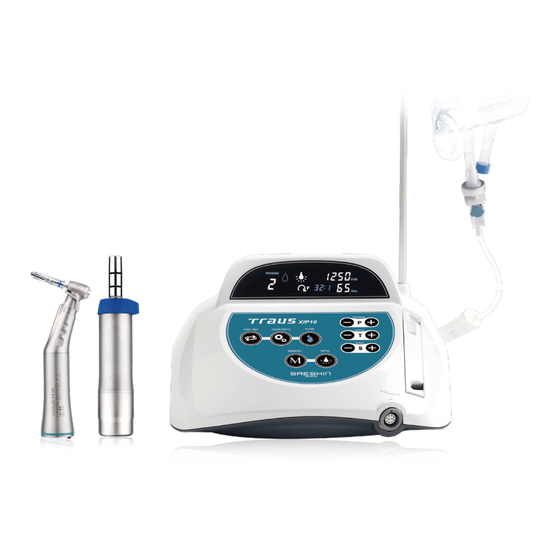
PRODUCT COMPONENTS * Please check all components are included. (Some components may be changed by the manufacture.) Component Component CONTROL BOX INTERNAL SPRAY NOZZLE ANGLE HANDPIECE FOOT POLE (Option) BLDC MOTOR MOTOR CAP For Autoclave FOOT CONTROLLER TUBE HOLDER MOTOR STAND TUBE CLAMP HANGER AC POWER CORD... - Page 8 PART NAME OF CONTROL BOX Main Power Switch Foot Controller Motor Connector Connector Main Power Socket Fuse Box Operation Direction Button Gear Ratio Button Irrigation Pump Button Program Button Torque Button Speed Button Optic Button Memory Button...
- Page 9 BUTTONS ON THE OPERATION PANEL Program Button: Use for selecting the set program number. (+) button for 1 stage up and (-) button for 1 stage down. Speed Button: Use for setting the speed (RPM). (+) button for 1 stage up and (-) button for 1 stage down. Keep pressing speed button to change the stage rapidly.
-
Page 10: Lcd Window
LCD WINDOW 1. Irrigation Volume Display : It shows the selected irrigation level. Level 0 is no volume and level 4 is maximum. 2. Program Number Display : 9 programmable programs set from 1 to 9. And it shows program 1 at every power on. 3. - Page 11 BUTTONS ON THE FOOT CONTROLLER - TRAUS FUS10 1. Program Button : Use the button to select the program. 1 stage increased per each press. 1 stage decreases when press this button above 3 seconds. (Program decrease function is not operated continuously. If you want to decrease program over the 2 stage, press the button after releasing the button.) 2.
- Page 12 CONNECTION OF EACH PART - Make sure the power is off before connect each part. (Otherwise, it might cause a malfunction.) 1. Motor Connection : Please insert the motor plug to the device correctly. (Place the arrow mark on top. See the picture below.) ( O ) ( X ) 2.
- Page 13 4. Irrigation Tube Connection to Pump Roller ① Please press the button to open the pump cover. ② Please place the irrigation tube correctly in the pump. ③ Please press the button to close the pump. - If you do not use it for long period, please open pump roller cover. Otherwise, the irrigation tube might be damaged.
- Page 14 6. Irrigation Tube Insertion : Lock the irrigation stopper placed between the irrigation tube needle and pack, then insert the irrigation tube needle to the pack in place with the pack downward. Irrigation Tube Needle Irrigation Stopper - If pump is operating while the tube is bent or the water does not come out, the tube can be broken or damaged.
-
Page 15: Operation Process
OPERATION PROCESS (1) Turn the main switch on. If the product is normal condition, it becomes standby mode with program 1 on the screen like below picture. (2) Choose the program. Press the button on the foot controller or button on the control box, the program changes by 1 stage. - Page 16 Error and Remedy When motor stops due to overload, disconnection or misuse, the error code explanation is below: Error Display Cause and Remedy Cause: Foot controller connection is wrong or Foot controller is malfunctioning. Err 01 Remedy: Check the foot controller connection. Press the speed control pedal on the foot controller.
-
Page 17: Maintenance Of The Product
MAINTENANCE OF THE PRODUCT 1. Cleaning ■ Angle Handpiece ① Rotate the head in a tap water about 10 seconds with maximum speed to remove the remains (blood, physiologic saline solution, etc.) and rinse. ※ Do not put tap water in the motor. ②... - Page 18 3. Lubrication Lubrication Product List · Angle handpiece Lubrication Method - Insert the nozzle to motor assembly part(the end part of angle) and spray lubricant 2~3 seconds. Optic Type Spray Nozzle Spray Non-Optic Type Spray Nozzle Spray - Do not insert the oil into the motor. It damages the bearing or causes fever. - If the continuous operation, please put the oil every an hour.
- Page 19 ATTENTION 1. Please read the notice below before operating the product. 1) Check the connection of every cords and correct operation when power-on. 2) Check the earth connection is safe. 3) Make sure to check the contact part to patient. 4) Check the voltage.
-
Page 20: Product Specification
PRODUCT SPECIFICATION 1) Control Box Model Name TRAUS XIP10 Input AC 100-120V / 220-240V, 50/60 Hz Fuse 5A / 2A Power Consumption 48 VA Maximum Irrigation Volume Max. 90 ㎖ / min ± 20% 2) Motor Optic Model Name TRAUS MBP10SL TRAUS MBP10SX 40,000 40,000... - Page 21 Compliance level Electromagnetic environment – guidance Portable and mobile RF communications equipment should be used no closer to any Conducted RF part of the TRAUS SIP10 including cables, 3Vrms IEC 61000-4-6 3Vrms than the recommended separation distance 150kHz to 80Mhz...
-
Page 22: Warranty
WARRANTY SAESHIN guarantees out product for 1 year from invoice date, and product warranty means that SAESHIN has responsibility of defective material or operation failure. The product warranty does not cover user’s misuse, wrong installation, inappropriate maintenance and repair, and normal wear of consumables such as bearings, spindle, gear, and rotator. - Page 23 SYMBOL Program Button Gear Ratio Button Speed Button Operation Direction Button Torque Button Irrigation Pump Button Memory Button Optic Button Operation Direction Button Program Button Irrigation Pump Button Manufacturer Consult Instruction For Use EC Representative General Caution Sign Serial Number Autoclave General Warning Sign General Prohibition Sign...
- Page 24 MEMO...
- Page 25 Unit 3D, North Point House North point Business Park New Mallow Road CORK, T23AT2P , Ireland +353 212066448 Tel. 82-53-587-2341 / Fax. 82-53-580-0999 대구광역시 달성군 다사읍 세천로 1길 52 (성서5차산업단지) Tel. 053-587-2345 / Fax. 053-580-0918 www.saeshin.com / traus@saeshin.com SOM-S047S-KE Rev.10 2020-03-01...
Need help?
Do you have a question about the Traus SIP10 and is the answer not in the manual?
Questions and answers