Table of Contents
Advertisement
Advertisement
Table of Contents
Troubleshooting

Related Manuals for Sega Rally 2 DX


Summary of Contents for Sega Rally 2 DX
- Page 1 Sega Rally 2 DX USER MANUAL © 1998 SEGA...
-
Page 2: Table Of Contents
TABLE OF CONTENTS INTRODUCTION OF THE OWNERS MANUAL GENERAL PRECAUTIONS 1. PRECAUTIONS TO BE HEEDED FOR OPERATION 2. NAME OF PARTS 3. ACCESSORIES 4. ASSEMBLY AND INSTALLATION 9~15 5. PRECAUTIONS TO BE HEEDED WHEN MOVING MACHINE 6. CONTENTS OF GAME 17~21 7. - Page 3 1st PRINTING MAR 98 DLX VERSION OWNER’S MANUAL OWNER’S MANUAL OWNER’S MANUAL OWNER’S MANUAL OWNER’S MANUAL SEGA ENTERPRISES, USA MANUAL NO. 4200-6374-02...
- Page 4 Warranty Your new Sega Product is covered for a period of 90 days from the date of shipment. This certifies that the Printed Circuit Boards, Power Supplies and Monitor are to be free of defects in workman- ship or materials under normal operating conditions. This also certifies that all Interactive Control Assemblies are to be free from defects in workmanship and materials under normal operating condi- tions.
-
Page 5: Introduction Of The Owners Manual
50” INCH Projector INTRODUCTION OF THE OWNERS MANUAL SEGA ENTERPRISES, LTD., has for more than 30 years been supplying various innovative and popular amusement products to the world market. This Owners Manual is intended to provide detailed descriptions together with all the necessary installation, game settings and parts ordering information related to the RALLY 2 DLX, a new SEGA product. -
Page 6: General Precautions 2~3
General Precautions Follow Instructions: All operating and use instructions should be followed. Attachments: Do not use attachments not recommended by the product manufacturer as they may cause hazards. Accessories: Do not place this product on an unstable cart, stand, tripod, bracket, or table. The product may fall, causing serious injury to a child or adult, and serious damage to the product. - Page 7 Safety Check: Upon completion of any service or repairs to this product, ask the service technician to perform safety checks to determine that the product is in proper operating condition. Heat: The product should be situated away from heat sources such as radiators, heat registers, stoves, or other prod- ucts (including amplifiers) that produce heat.
-
Page 8: Precautions To Be Heeded For Operation
1 . PRECAUTIONS TO BE HEEDED FOR OPERATION In order to prevent accidents, be sure to comply with the following points before and during operation. PRECAUTIONS TO BE HEEDED FOR OPERATION BEFORE STARTING THE OPERATION In order to avoid accidents, check the following before starting the operation: Check if all of the adjusters are in contact with the surface. - Page 9 PRECAUTIONS TO BE HEEDED DURING OPERATION To avoid injury and accidents, those who fall under the following catagories are not allowed to play the game: * Intoxidated persons * Those who have high blood pressure or heart problems. * Those who have experienced muscle convulsion or loss of consciousness when playing video games, etc.
-
Page 10: Name Of Parts
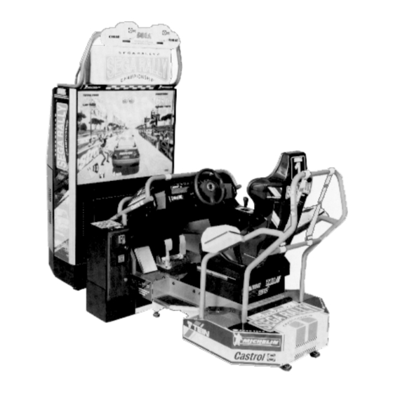
2 . NAME OF PARTS MARQUEE FRONT CABINET REAR CABI AC UNIT COIN CHUTE DOOR CASH BOX WEIGHT WIDTH LENGTH HEIGHT GAME SPECIFICATIONS All measurements are in inches Weight-DURING SHIPPING 1250 LBS. 42” 23” 22.5” 49 LBS. MARQUEE 44.5” 31” 70”... -
Page 11: Accessories
3 . ACCESSORIES... - Page 12 THE SHIPMENT METHOD DESCRIBED BELOW ONLY APPLIES TO ‘MODEL 3’ BOARDS CONTAINED IN THE FOLLOWING GAMES: LOST WORLD, VIRTUA FIGHTER 3, SUPER GT, SEGA BASS FISHING, STRIKER 2 HARLEY DAVIDSON, RALLY 2 !!NEVER SHIP MODEL 3 GAME BOARDS !!NEVER SHIP MODEL 3 GAME BOARDS...
-
Page 13: Assembly And Installation
4 . ASSEMBLING AND INSTALLATION Assembling should be performed as per this manual. Since this is a complex machine, erroneous assembling may cause damage to the machine, or malfunctioning to occur. When assembling, be sure to perform work by plural persons. Depending on the assembly work, there are some cases in which performing the work by a single person can cause personal injury or parts damage. - Page 14 ASSY OF FRONT CABI Installing the Billboard by one person is difficult. Be sure to use plural persons to perform work safely and accurately. To perform work safely and securely, be sure to prepare a step which is in a secure and stable condition. Performing work without using a step can caus e a violent falling down accident.
- Page 15 JOINING THE CABINETS Due to its large size, it is very difficult for one person alone to install the billboard, Make sure 2 or more persons are available to perform this work. Attempting to perform the installation alone can cause an accident. Install the Joint Bracket L &...
- Page 16 SECURING IN PLACE (ADJUSTER ADJUSTMENT) Be sure to have all the Adjusters make contact with the surface. Un- less the Adjusters come into contact with the surface, the Cabinet can move of itself, causing an accident. This machine has 8 each of casters and adjusters (shown below). When the installation position is determined, cause the adjusters to come into contact with the floor directly, make adjustments in a manner so that the casters will be raised approximately 5mm.
- Page 17 POWER SUPPLY Ensure that the power cord is not exposed on the surface (passage, etc.). If exposed, they can be caught and are susceptible to damage. If damaged, the cord can cause an electric shock or short circuit. Ensure that the wiring position is not in the customer's passage way or the wiring has protective covering.
- Page 18 ASSEMBLING CHECK The TEST MENU allows for each part of the cabinet to be checked, the Monitor to be adjusted, and the coin and game related various functions to be performed. MEMORY TEST Selecting the MEMORY TEST on the test mode menu screen causes the on-board memory to be tested automatically.
- Page 19 SOUND TEST In the TEST mode, selecting SOUND TEST causes the screen, on which sound related BD and wiring connec- tions are tested, to be displayed. be sure to check if the sound is satisfactorily emitted from each of speaker and the sound volume is appropriate.
-
Page 20: Precautions To Be Heeded When Moving Machine
5 . PRECATIONS TO BE HEEDED WHEN MOVING THE MACHINE When moving the machine, be sure to pull out the plug from the power supply. Moving the machine with the plug as is inserted can damage the power cord and cause a fire or elec- tric shock. -
Page 21: Contents Of Game
6 . CONTENTS OF GAME The following explanations apply to the case the product is functioning satisfactorily. Should there be any moves different from the following contents, some sort of faults may have occured. Immediately look into the cause of the fault and eliminate the cause thereof to ensure satisfactory operation. - Page 22 WHEN PLAYING IN TH ECHAMPIONSHIP MODE Note: In the interactive play, CHAMPIONSHIP MODE can not be selected. The car select mode appears. Select from among 6 types. Depending on the type of car, your operat- ing sensation may somewhat vary. Choose the desired car by turning the Steering Wheel, and confirm with the Accelerator Pedal.
- Page 23 On the upper left portion of the screen, total time & lap time are displayed. The remaining time is shown at the top center and navigation icon is seen at the loer part of the top center. on the upper right-hand side, the present player’s position as well as the stage’s top 3 times are displyed.
- Page 24 WHEN PLAYING IN THE PRACTICE MODE The Course Select mode appears. Turn the Steering Wheel to select and confirm with pedal. In case of communica- tion play, the course is selected by majority. The Car Select Mode appears. Select from among the 6 types.
- Page 25 The NAME ENTRY MODE appears. Turn the Steering Wheel to choose input characters, and confirm with pedal. After inputing the 3 characters, game start On the upper left portion of the screen, total time & lap time are displayed. The remaining time is shown at the top center and navigation icon is seen at the loer part of the top center.
-
Page 26: Explanation Of Test And Data Display
7 . EXPLANATION OF TEST AND DATA DISPLAY By operating the switch unit, periodically perform the tests and data check. When installing the machine intitally or collecting cash, or when the machine does not function correctly, perform checking in accordance with the explanations given in this section. -
Page 27: Switch Unit And Coin Meter
7 - 1 SWITCH UNIT AND COIN METER Never touch places other than those specified. Touching places not specified can cause electric shock and short circuit. Adjust to the optimum sound volume by considering the environmental requirements of the installation location. If the COIN METER and the game board are electrically disconnected, game play is not possible. -
Page 28: Test Mode
7 - 2 TEST MODE This mainly checks if the operation of the game BD is accurate, and allows for COIN ASSIGNMENTS/GAME ASSIGNMENTS setting and Projector adjustments. T h e F o l l o w i n g F I G U R E S / T A B L E S s h o w t h e f a c t o r y r e c o m m e n d e d s e t t i n g s . T h e F o l l o w i n g F I G U R E S / T A B L E S s h o w t h e f a c t o r y r e c o m m e n d e d s e t t i n g s . -
Page 29: Steering Reaction Test
7 - 4 STEERING REACTION TEST This test allows Steering Wheel reaction mechanism to be tested and eaction force to be set. Press the Service Button to STEERING REACTION TEST bring the arrow to the desitred item to be selected, and press the Test Button to enter the selected item. -
Page 30: Input Test
7 -5 INPUT TEST Select INPUT TEST to have the screen shown below appear and to observe the status of each switch and the Control Panel’s each V.R. Value. Periodically check the status of each switch and V.R. on this screen. By pressing each switch, if the display onthe right-hand side of the name of each switch changes to ON from OFF, the SW INPUT TEST... -
Page 31: Sound Test
7 - 7 SOUND TEST This enables sound used in the game to be checked. SOUND TEST Sound related memory and each speaker are checked. EFFECT: Sound effects during game. VOICE: EFFECT SE_CHECK1 VOICE VO_30 Voice of announcement and naration. B.G.M. -
Page 32: Game Assignments
7 - 9 GAME ASSIGNMENTS Selecting the GAME ASSIGNMENTS in the MENU mode causes the present game settings to be displayed and also the game settings changes (game difficulty, etc.) can be made. Each item displays the following content. SETTING CHANGE PROCEDURE Setting changes cannot be stored unless the TEST BUTTON is pressed while the arrow is on EXIT. -
Page 33: Coin Assignments
7 - 10 COIN ASSIGNMENTS The “COIN ASSIGNMENTS” mode permits you to set the start number of credits, as well as the basic numbers of coins and credits. This mode expresses “how many coins correspond to how many credits.” SETTING CHANGE PROCEDURE Setting changes cannot be stored unless the TEST BUTTON is pressed while the arrow is on EXIT. - Page 34 TABLE 7.10a COIN/CREDIT SETTING (COIN CHUTE COMMON TYPE) SETTING FUNCTIONING OF CHUTE#1 SETTING #1 1 COIN 1 CREDIT SETTING #2 1 COIN 2 CREDITS SETTING #3 1 COIN 3 CREDITS SETTING #4 1 COIN 4 CREDITS SETTING #5 1 COIN 5 CREDITS SETTING #6 1 COIN...
- Page 35 MANUAL SETTING Selecting MANUAL SETTING in the COIN ASSIGNMENTS mode displays the following screen. MANUAL SETTING COIN TO CREDIT 1 COIN 1 CREDIT BONUS ADDER NO BONUS ADDER COIN CHUTE #1 MULTIPLIER 1 COIN COUNTS AS 1 COIN COIN CREDIT COIN CHUTE #2 MULTIPLIER 1 COIN COUNTS AS 1 COIN COIN...
-
Page 36: Bookkeeping
7 - 11 BOOKKEEPING Choosing BOOKKEEPING in the MENU mode displays the data of operating status up to the present are shown on 2 pages. Press the TEST BUTTON to proceed to PAGE 2/2. COIN CHUTE#*: BOOKKEEPING PAGE1/2 Number of coins put in each Coin Chute. COIN CHUTE #1 XXXXXXXXXXX COIN CHUTE #2... -
Page 37: Steering Mecha
8. STEERING MECHA In order to prevent an electric shock and short circuit, be sure to turn power off before performing work by touching the interior parts of the product. Be careful so as not to damage wirings. Damaged wiring can cause an electric shock or short circuit accident. -
Page 38: Replacing The And Adjusting The Handle's Vr
8 - 2 REPLACING AND ADJUSTING THE HANDLE’S VR Never touch places other than those specified. Touching places not specified can cause electric shock and/or short circuit. After the replacement or adjustment of the VR, be sure to set the variable value of the VR in the test mode’s Volume Setting. -
Page 39: Greasing
8 - 3 GREASING Never touch places other than those specified. Touching places not specified can cause electric shock and/or short circuit. After the replacement or adjustment of the VR, be sure to set the variable value of the VR in the test mode’s Volume Setting. Apply greasing to the Volume gear mesh portion every 3 months. -
Page 40: Shift Lever
9. SHIFT LEVER In order to prevent electric shock and short circuit, be sure to turn off the power before performing work on the interior parts of the product. Be careful not to damage wiring. Damaged wiring can cause electric shock or short circuit. -
Page 41: Switch Replacement
REMOVAL OF SHIFT COVER 9 - 2 SWITCH REPLACEMENT Each microswitch is secured with 2 screws. Remove the 2 screws and replace the Microswitch. After replacing the Switch, check to see if the switch is inputted as per Shift Lever operation in the Test Mode.d... -
Page 42: Accel & Brake
10. ACCEL & BRAKE(S) In order to prevent an electric shock and short circuit, be sure to turn power off before performing work by touching the interior parts of the product. Be careful so as not to damage wirings. Damaged wiring can cause an electric shock or short circuit accident. -
Page 43: Greasing 39~40
Check Volume values in the Test Mode. Since work is performed inside the energized cabinet, be very careful so as not to touch undesignated portions. Touching places not specified can cause an electric shock or short circuit. Take out the 2 truss screws and remove the Front Cover from the Accel. -
Page 44: Greasing To The Handbrake
In order to prevent an electric shock and short circuit, be sure to turn power off before performing work byt ouching the interior parts of the product. Be careful so as not to damage wirings. Damaged wiring can cause an electric shock or short circuit accident. -
Page 45: Maintenance Of Mechanism Unit
11. MAINTENANCE OF MECHANISM UNIT Be careful not to edamage wirings. Damaged wirings can cause an electric shock or short circuit accident. Do not touch places other than those specified. Touching places not specified can cause electric shock or short circuit accident. When performing work, be sure to use plural workers. - Page 46 LOOSEN THE VOLUME Loosen the 2 screws which secure the Volume Bracket, and move the Bracket. Move the Volume Bracket to disengage the gear mesh. With the front part of the Cockpit inclined up to the top position, adjust gear mesh to ensure the volume value display is within the range of 80 -/+10H.
-
Page 47: Greasing 43~44
11 - 2 GREASING Be careful not to edamage wirings. Damaged wirings can cause an electric shock or short circuit accident. Do not touch places other than those specified. Touching places not specified can cause electric shock or short circuit accident. When performing work, be sure to use plural workers. - Page 48 GREASING TO THE SPRING PORTION UNDERNEATH THE SEAT Once every 3 months, apply greasing to the 2 Spring and Spring installation portion under- neath the seat. Remove the 4 bolts which secure the seat, and for safety, one person is to incline the seat and another person is to apply greasing.
-
Page 49: Replacing The Safety Rubber 45~46
11 - 3 REPLACING THE SAFETY RUBBER The Safety Rubber is an important, hazard-preventive part. Before commencing daily operation, be sure to check for damage and omission. Operating with the Safety Rubber as is damaged or omitted can cause the customers’ fingers to be caught. INSTALLATION OF SAFETY RUBBER MIDDLE SIDE To install RUBBER MIDDLE SIDE to the side oppisite the Cockpit, turn over the RUBBER and use HOLDER LEFT S. -
Page 51: Coin Selector
12 . COIN SELECTOR HANDLING THE COIN JAM If the coin is not rejected when the REJECT BUTTON is pressed, open the coin chute door and open the selector gate. After removing the jammed coin, put a normal coin in and check to see that the selector correctly functions. - Page 52 OPTIONAL DOLLAR BILL ACCEPTOR THE COIN DOOR ASSEMBLY USED ON RALLY 2 DLX Version RALLY 2 DLX Version RALLY 2 DLX Version RALLY 2 DLX Version RALLY 2 DLX Version COMES EQUIPPED TO ACCEPT A DOLLAR BILL ACCEPTOR. ALL NEEDED WIRING CONNECTIONS ARE CONVIENENTLY LOCATED INSIDE THE GAME FOR THIS APPLICATION.
-
Page 54: Projector
13. PROJECTOR Since the projector screen is susceptible to damage, pay careful atten- tion to its handling. When cleaning, freain from using water or volatile chemicals. Since the Projector has been adjusted at the time of shipment, avoid making further adjustments without good reason. Fine adjustments are stored inthe Projector. -
Page 55: Mitsubishi Projector 51~52
13 - 2 MITSUBISHI PROJECTOR Although Remote Control Buttons other than those specified below do not function even if pressed during Convergence Adjustment, do not press them during adjustment work so as to avoid causing malfunctioning. Operate the Remote Control towards the PTV screen. If directed other than to the PTV screen, the Remote Control does not function. - Page 56 Every time the PICTURE Key is pressed, the Adjustment mode proceeds sequentially in order as above. In each Adjustment mode, press the + or - key to make adjsutment. In each Adjustment mode, unless the key input (value or image variation) is effectively performed within approximately 6 seconds, the Adjustment mode is automati- cally cancelled and shifts to the normal image.
-
Page 57: Toshiba Projector
13-3 TOSHIBA PROJECTOR Do not touch places other than those specified. Touching places not specified can cause an electric shock or short circuit accident. TOSHIBA PROJECTOR has two different types, i.e., one equipped with the Control Panel and the other without the Control Panel. When adjusting, be sure to confirm the type used. TOSHIBA PROJECTOR CONTROL PANEL STATIC CONVERGENCE ADJUSTMENT (With the Control Panel) Do not press undesignated key. - Page 58 When intially installing the machine, or when the installa- tion position is changed, check to see if the Test Pattern is in the central, well balanced position. If deviated, adjust the green position by using the Adjust Key “up/down/left/ right” in the manner so as to improve the balance (L&R, and T&B are approximately equal as shown).
-
Page 59: Toshiba Projector
ADJUSTMENT OF TOSHIBA PROJECTOR (THE TYPE WITHOUT CONTROL PANEL) The Remote Control is used for adjustment of the type without Control Panel. When adjsuting the Projector, direct the Remote Control’s light emitting portion towards the Projector Screen. REMOTE CONTROL BUTTONS AUTOMATIC COLOR MATCHING The Projector may be subject to color deviations affected by earth magnetism, the building’s steel frames, etc. - Page 60 ADJUSTING THE ON-SCREEN CONTRAST Although the on-screen picture quality has been adjusted at the time of shipment from the factory, the on-screen contrast can be readjusted if desired. When the Game Board is replaced, readjustment may be necessary. Changing the CONTRAST causes the light and shade of the on-screen images to be changed.
- Page 61 ADJUSTING THE ON-SCREEN BRIGHTNESS Although the on-screen picture quality has been adjusted at the time of shipment from the factory, the on-screen contrast can be readjusted if desired. When the Game Board is replaced, readjustment may be necessary. Changing the BRIGHTNESS causes the light and shade of the on-screen images to be changed.
- Page 62 ADJUSTING THE ON-SCREEN CONTRAST Although the on-screen display position (H. POSI, V. POSI) has been adjusted at the time of ship- ment from the factory, the on-screen contrast can be readjusted if desired. When the Game Board is replaced, readjustment may be necessary. When discontinuing the adjustment, choose EXIT from the menu at the stage of procedure ”2”...
- Page 63 ADJUSTING THE SCREEN SIZE Although the on-screen size (H. SIZE, V. SIZE) has been adjusted at the time of shipment from the factory, the on-screen contrast can be readjusted if desired. When the Game Board is replaced, readjustment may be necessary. When discontinuing the adjustment, choose EXIT from the menu at the stage of procedure and press the...
- Page 64 CONVERGENCE ADJUSTMENT (manual color matching) To avoid circuitry malfunctioning due to electrical load increase, never utilize CONVERGENCE ADJUSTMENT (Line Convergence Adjustment in particular) for adjusting screen size changes. There is no means to restore the Convergence Adjustment data once stored, to its original state. To avoid changing the screen size by errone- ously using convergence adjustment, do not perform the green Line Convergence Adjustment.
- Page 65 STATIC CONVERGENCE ADJUSTMENT In the static convergence adjustment, each of red and blue images is comprehensively moved to and superimposed on the green color. If automatic color matching function is not sufficiently satisfactory, perform this adjustment. Be sure to perform automatic color matching before starting the above adjustment.
- Page 66 POINT CONVERGENCE ADJUSTMENT In the POINT CONVERGENCE adjustment, each of red, green, and blue images is partially moved for color matching. The adjustment may be necessary when the Game Board is replaced or changed, or screen size is changed. Be sure to perform automatic color matching before starting.
- Page 67 LINE CONVERGENCE ADJUSTMENT In the LINE CONVERGENCE ADJUSTMENT, the adjustment point of column line (vertical) or row line (horizontal) is comprehensively moved for color matching. It is convenient to utilize this adjustment when color of the column line or row is uniformly deviated. NOTE 1: When the MODE button is repeatedly pressed, the adjustment modes will circulate as follows:...
-
Page 68: Replacement Of Fluorescent Lamp
14 . REPLACEMENT OF FLUORESCENT LAMP When performing the work, be sure to turn power off. Working with power on can cause an electric shock or short circuit acci- dent. The Fluorescent Lamp, when it gets hot, can cause burns. Be very careful when replacing the Fluorescent Lamp. -
Page 69: Periodic Inspection Table
Move the Seat to the rearmost portion and apply spray greasing to the portion shown at the right once every 3 months by using NOK KLUBER L60 or GREASE MATE SEGA PART No. 090-0066. After greasing, move seat a few times forward and backward so as to allow the grease to be applied all over uniformly. -
Page 70: Troubleshooting
16. TROUBLESHOOTING In order to prevent an electrical shock, be sure to turn power off before performing work by touching the interior parts of this product. Be careful so as not to damamge wirings. Damaged wiring can cause an electric shock or short circuit accident. -
Page 71: Troubleshooting
TROUBLESHOOTING TABLE 14.b... -
Page 72: Game Board
17 . GAME BOARD In order to prevent an electrical shock, be sure to turn power off before performing work by touching the interior parts of the product. Be careful so as not to damage wirings. Damaged wiring can cause an electric shock or short circuit accident. - Page 73 Remove the 2 screws which secure the wooden base on which the Shield Case is mounted. Withdraw the wooden base with the Shield Case as is mounted. At this time, use care so as not to damage wiring and optic fiber cable.
-
Page 74: Replacement Of Fuses
17 - 2 REPLACEMENT OF FUSE In order to prevent an electric shock, be sure to turn power off before performing work by touching the interior parts of the product. Be careful so as not to damage wirings. Damaged wiring can cause an electric shock or short circiut accident After eliminating the cause of the blowing of fuse, replace the fuse. -
Page 75: Composition Of The Game Board
17 - 3 COMPOSITION OF GAME BOARD GAME BD SRT TWIN (833-13373) NOTE: THIS PICTURE IS FOR REFERENCE ONLY!! UNIT IS NOT TO BE OPENED. EXPOSING THE GAME BD FOR ANY REASON MAY VOID WARRANTY. -
Page 76: Design Related Parts
18. DESIGN RELATED PARTS... -
Page 77: Parts List 73~124
DESIGN RELATED PARTS... - Page 78 19 . PARTS LIST TOP ASSY SEGA RALLY 2 DX...
- Page 79 TOP ASSY SEGA RALLY 2 DX ITEM NO. PART NO. DESCRIPTION SRT-1000 ASSY FRONT CABINET SRT-3000 ASSY REAR CABINET DYN-0011 DENOMI PLATE W/O ORIGINAL 421-7308-63 DENOMINATION SHEET 1 GAME~ 422-0670-01-01 PLAY INSTR SH SRT DX SRT-0001 JOINT BRKT L SRT-0002...
- Page 80 ASSY FRONT CABINET (SRT-1000)
- Page 81 ASSY FRONT CABINET (SRT-1000) ITEM NO. PART NO. DESCRIPTION SRT-0500 ASSY BILLBOARD SRT-1020 ASSY BACK LID SRT-1050 AC UNIT SRT-1100 ASSY FRONT BASE SRT-4000 ASSY MAIN BD SRT-4100 ASSY PWR SUPLY SRT-4200 ASSY MPEG SRT-1003 PTV JOINT BRKT SPG-0001 BILLBOARD HOOK SRT-4300 ASSY DRIVE BD SRT-1102...
- Page 82 ASSY BILLBOARD (SRT-0500) ITEM NO. PART NO. DESCRIPTION SRT-0501 BILLBOARD FRAME SRT-0502 ASSY BILLBOARDBOX SRT-0504 ASSY LIGHT COVER SRT-0507 WIRE COVER...
- Page 83 ASSY BILLBOARD BOX (SRT-0502) ITEM NO. PART NO. DESCRIPTION SRT-0503 BILLBOARD CASE SRT-0204 BILLBOARD LID SRT-0205 BILLBOARD 253-5457 FL HOLDER LOCAL PURCHASE ASSY FL20W EX W/CONN...
- Page 84 ASSY LIGHT COVER (SRT-0504) ITEM NO. PART NO. DESCRIPTION SRT-0505 LIGHT COVER SRT-0506 LIGHT COVER BASE SRT-0209 L BRKT SRT-2010 LIGHT COVER BRKT 253-5461 LIGHT COVER CIBIE...
- Page 85 ASSY BACK LID (SRT-1020) ITEM NO. PART NO. DESCRIPTION SPG-1021 BACK LID 105-5238-91 FAN BRKT 105-5239-04 AIR VENT 601-8543 FAN GUARD 260-0011-02 AXIAL FLOW FAN AC 100V 50-60Hz...
- Page 86 AC UNIT (SRT1-1050) ITEM NO. PART NO. DESCRIPTION TTR-1251 AC BRKT LOCAL PURCHASE 7A FUSE Slo 509-5453-91-V-B SW ROCKER J8 V-B 600-5843-25 CA & PLUG ASSY L=2.5M 280-5134-6N34 BUSHING STRAIN RELIEF 6N34...
- Page 87 ASSY FRONT BASE (SRT-1100)
- Page 88 ASSY FRONT BASE (SRT-1100) ITEM NO. PART NO. DESCRIPTION SRT-1101 WOODEN FRONT BASE SRT-1103 CATCH BRKT SRT-1104 LEG BRKT R ARC-1006 LEG BRACKET 117-5233 LEG BRKT BLACK 999-0167 LEG ADJUSTER BOLT 999-0169 CASTER 2 1/2"...
- Page 89 ASSY MAIN BD (SRT-4000) ITEM NO. PART NO. DESCRIPTION SPG-4001 WOODEN BASE L SRT-4050 ASSY SHIELD CASE 105-5241 SHIELD CASE BRKT...
- Page 90 ASSY SHIELD CASE (SRT-4050) ITEM NO. PART NO. DESCRIPTION 105-5245X SHIELD CASE MODEL 3 NVS 105-5242X SHIELD CASE LID MODEL 3 839-0932 FILTER BD MODEL 3 SPG 833-13371 GAME BD SRT DX 260-0064 FAN MOTOR DC 12V...
- Page 91 ASSY PWR SPLY (SRT-4100)
- Page 92 ASSY PWR SPLY (SRT-4100) ITEM NO. PART NO. DESCRIPTION SRT-4101 WOODEN BSE PWR SPLY BY-4102 FAN MOTOR BRACKET 838-11650-22 EQ. PWR AMP SPG TWIN A 838-11856-01-UL CONNECT BD W/FUSE & COVER UL 838-13142 BASS AMP 50WX2 839-0542 AUDIO MIX BD 560-5387 XMFR 23V9.6Ax2 12.5V6x3 19V2A 400-5330-02-91...
- Page 93 ASSY MPEG (SRT-4200) ITEM NO. PART NO. DESCRIPTION SRT-4201 WOODEN BASE MPEG SRT-4250 ASSY SHIELD CASE MPEG 838-11650-42 EQ. PWR AMP SRT DX M...
- Page 94 ASSY SHIELD CASE MPEG (SRT-4250) ITEM NO. PART NO. DESCRIPTION 105-5315 SHIELD CASE MPEG 105-5316 SHIELD CASE LID MPEG 105-5317 SHIELD CASE BRKT MPEG 837-13375 SOUND BD SRT DX 839-1021 FLT BD DIGITAL SOUND...
- Page 95 ASSY DRIVE BD (SRT-4300)
- Page 96 ASSY DRIVE BD (SRT-4300) ITEM NO. PART NO. DESCRIPTION SRT-4301 WOODEN BASE DRIVE 838-12912-91 SERVO MOTOR DRIVE BD 838-13366 DRIVE BD SRT 839-0451-01 LIGHT CONTROL BD TTR 839-1011-01 SSR 1EA BD BR 400-5454 RECTIFIER DC 45V 270-5020 NOISE FILTER AC250V 6A...
- Page 97 ASSY REAR CABINET (SRT-3000)
- Page 98 ASSY REAR CABINET (SRT-3000) ITEM NO. PART NO. DESCRIPTION SRT-2000 ASSY ROLL BAR F SRT-2300 ASSY COCKPIT BASE SRT-2350 ASSY POWDER BRAKE SRT-2400 ASSY SEAT SRT-2460 ASSY FLOOR CENTER SRT-2200 ASSY ACCEL & BRAKE SRT-3100 ASSY COIN CHUTE TOWER SRT-3200 ASSY PULLY BOX SRT-3300 ASSY ROLL BAR R...
- Page 99 ASSY REAR CABINET (SRT-3000) ITEM NO. PART NO. DESCRIPTION SRT-3041 HOLDER FRONT SIDE SRT-3042 VOL BASE SRT-3043 VOL BRKT SRT-3044 END SHAFT L SRT-3045 END SHAFT COLLAR L SRT-3046 REAR COVER SIDE L SRT-3047 REAR COVER SIDE R SRT-3048 HOLDER MIDDLE SRT-3049 CONN PLATE L SRT-3050...
- Page 100 REAR BASE (SRT-3001) ITEM NO. PART NO. DESCRIPTION SRT-3001-A REAR BASE BLANK SRT-3001-B STICKER REAR SIDE L SRT-3001-C STICKER REAR SIDE R 999-0169 CASTER 2 1/2" 999-0167 LEG ADJUSTER...
- Page 101 ASSY ROLL BAR F (SRT-2000)
- Page 102 ASSY ROLL BAR F (SRT-2000) ITEM NO. PART NO. DESCRIPTION SRT-2100 ASSY HANDLE MECHA SRT-2150 ASSY SW PLATE SPG-2150 ASSY 4 SPEED SHIFTER SRT-2001 ROLL BAR F SRT-2002 CNT PNL COVER SRT-2003 SHIFT COVER SRT-2004 SHIFT BOX SRT-2005 PANEL COVER LOWER SRT-2006 SP BRKT UPPER SRT-2007...
- Page 103 ASSY HANDLE MECHA (SRT-2100)
- Page 104 ASSY HANDLE MECHA (SRT-2100) ITEM NO. PART NO. DESCRIPTION SPG-2501 HANDLE BASE SPG-2502 BASE LID SPG-2503 HANDLE SHAFT SPG-2504 PULLEY 20 S5M SPG-2505 PULLEY 60 S5M SPG-2506 MOTOR BRKT SPG-2507 VR BRKT SPG-2108 STOPPER BOLT SPG-2109 STOPPER RUBBER SPG-2453 KEY 4X4X40 ASK-3502 MOTOR SPACER ASK-3503...
- Page 105 ASSY SW PLATE (SRT-2150) ITEM NO. PART NO. DESCRIPTION SRT-2151 SW PLATE 509-5838-Y SW PB LW1L-15Y-TK1670 509-5495-05 PUSH BUTTON BLUE...
- Page 106 ASSY 4 SPEED SHIFTER (SPG-2150)
- Page 107 ASSY 4 SPEED SHIFTER (SPG-2150) ITEM NO. PART NO. DESCRIPTION SPG-2151 SHIFT KNOB SPG-2152 STOPPER RUBBER SPG-2153 FRONT BASE SPG-2154 SLIDE COVER SPG-2155 SLIDE PLATE SPG-2156 REAR BASE SPG-2157 RUBBER BLOCK 45 SPG-2158 RUBBER BLOCK 65 SPG-2159 INSULATOR SHEET SPG-2160 SHAFT CASE SPG-2161 SHAFT BOLT...
- Page 108 ASSY ACCEL&BRAKE (SPG-2200)
- Page 109 ASSY ACCEL&BRAKE (SPG-2200) ITEM NO. PART NO. DESCRIPTION SPG-2201 BASE SPG-2202 ACCEL PEDAL SPG-2203 BRAKE PEDAL SPG-2204 ACCEL SPRING SPG-2205 BRAKE SPRING SPG-2206 SHAFT SPG-2207 ACCEL GEAR SPG-2208 BRAKE GEAR SPG-2209 NUETRAL STOPPER SPG-2210 VR PLATE ACCEL SPG-2211 VR PLATE BRAKE SPG-2212 AMPL GEAR SPG-2213...
- Page 110 ASSY COCKPIT BASE (SRT-2300)
- Page 111 ASSY COCKPIT BASE (SRT-2300) ITEM NO. PART NO. DESCRIPTION SRT-2470 ASSY SIDE STEP SRT-2301 COCKPIT BASE SRT-2302 BANK SHAFT SRT-2303 BANK SHAFT BRKT L SRT-2304 BANK SHAFT BRKT R SRT-2305 KEY 7X8X118 SRT-2306 SIDE STEP R SRT-2307 FOOT REST SRT-2308 FOOT REST COVER SRT-2309 BASS BRKT...
- Page 112 ASSY SIDE STEP (SRT-2470) ITEM NO. PART NO. DESCRIPTION SRT-2471 SIDE STEP SRT-2472 STEP MAT SRT-2473 CORNER SASH L SRT-2474 CORNER PLATE A SRT-2475 CORNER PLATE B SRT-2476 NON SLIP MAT L...
- Page 113 ASSY POWDER BRAKE (SRT-2350)
- Page 114 ASSY POWDER BRAKE (SRT-2350) ITEM NO. PART NO. DESCRIPTION SRT-2351 FRONT MECHA BASE SRT-2352 POWDER BRAKE SHAFT SRT-2353 IDLER SHAFT SRT-2354 IDLER COLLAR SRT-2355 PULLEY S8M 18 SRT-2356 IDLER SRT-2357 KEY 7X7X40 SRT-2360 KEY 7X8X36 SRT-2359 FLT WSHR 12.5-36-2 601-10036 POWDER BRAKE 12NM 050-U00800 U NUT M8...
- Page 115 ASSY SEAT (SRT-2400)
- Page 116 ASSY SEAT (SRT-2400) ITEM NO. PART NO. DESCRIPTION SPG-2401 UPPER SEAT SPG-2402 LOWER SEAT SRT-2401 SEAT BASE SRT-2402 SEAT FRAME SRT-2403 SEAT REAR COVER SRT-2404 INCLINED SEAT TRAY STC-1608 SPEAKER NET L STC-1609 SPEAKER NET R SRT-2405 CABLE BEAR BRKT SRT-2406 FRONT TRAY COVER A SRT-2407...
- Page 117 ASSY HAND BRAKE (SRT-2200)
- Page 118 ASSY HAND BRAKE (SRT-2200) ITEM NO. PART NO. DESCRIPTION SRT-2201 PIPE SHAFT SRT-2202 PIPE HOLDER SRT-2203 HOLDER SHAFT SRT-2204 STOPPER SHAFT N SRT-2205 STOPPER SHAFT SRT-2206 SPRING SRT-2207 SENSOR STAY SRT-2208 PIPE GUIDE SRT-2209 GUIDE BRKT SRT-2210 FRONT COVER SRT-2211 SIDE COVER A SRT-2212 SIDE COVER B...
- Page 119 ASSY FLOOR CENTER (SRT-2460) ITEM NO. PART NO. DESCRIPTION SRT-2461 FLOOR CENTER SRT-2462 FLOOR MAT SRT-2463 CORNER SASH A SRT-2464 CORNER SASH B SRT-2465 CORNER SASH C SRT-2466 CORNER SASH D SRT-2467 NONSLIP MAT C...
- Page 120 ASSY COINCHUTE TOWER (SRT-3100)
- Page 121 ASSY COINCHUTE TOWER (SRT-3100) ITEM NO. PART NO. DESCRIPTION SRT-3150 SW UNIT HLD-3501 COIN CHUTE TOWER INY-1162 METER BRKT INY-1163 METER HOLE LID DP-1167 TNG LKG 105-5171 CHUTE PLATE SINGLE BOX-CASH CASH BOX 220-5482-92-~ ASSY C.C. 2DR 220-5412 MAG CNTR W/CONN 220-5575 CAM LOCK MASTER W/O KEY 220-5574...
- Page 122 SW UNIT (SRT-3150) ITEM NO. PART NO. DESCRIPTION SRT-3151 SW BRKT SRT-3152 VR COVER 509-5028 SW PB 1M 220-5179 VOL CONT B-5K OHM 220-5296 VOL CONT 5K OHMX2+/-10% RV24G 601-0042 KNOB 22M...
- Page 123 ASSY PULLEY BOX (SRT-3200)
- Page 124 ASSY PULLEY BOX (SRT-3200) ITEM NO. PART NO. DESCRIPTION SRT-3201 PULLEY BOX LOWER SRT-3202 MAIN SHAFT SRT-3203 DRIVE PULLEY S8M SRT-3204 MAIN SHAFT HOLDER SRT-3205 MOTOR BRKT SRT-3206 KEY 5X5X17 SRT-2357 KEY 7X7X40 350-5534-01 MOTOR AC100V 90W 1/25 111-1122 COUPLING AL-075 601-10039 TIMING BELT 250 S8M 1056 100-5316...
- Page 125 ASSY ROLL BAR R (SRT-3300)
- Page 126 ASSY ROLL BAR R (SRT-3300) ITEM NO. PART NO. DESCRIPTION SRT-3301 ROLL BAR R SRT-3302 SPEAKER COVER L SRT-3303 SPEAKER COVER R SRT-3304 REAR SP BRKT SRT-3305 REAR SP SUPPORT L SRT-3306 REAR SP SUPPORT R SRT-3307 BELT R SRT-3308 BELT HOLDER A SRT-3309 BELT HOLDER B...
- Page 127 ASSY BRAKE (SRT-3400)
- Page 128 ASSY BRAKE (SRT-3400) ITEM NO. PART NO. DESCRIPTION SRT-3401 BRAKE SHAFT SRT-3402 BRAKE BRKT A SRT-3403 BRAKE BRKT B SRT-3404 END SHAFT SRT-3405 ROD M12 SPG-2357 KEY 7X7X32 SRT-3045 END SHAFT COLLAR L 601-10005 BRAKE BXH-16A 100-5266 BEARING FAI25 100-5307 RODEND RBH12 030-000820-S HEX BLT W/S M8X20...
Need help?
Do you have a question about the Rally 2 DX and is the answer not in the manual?
Questions and answers