
Subscribe to Our Youtube Channel
Related Manuals for Broadcom Brocade G730


Summary of Contents for Broadcom Brocade G730
- Page 1 ® Brocade G730 Switch Hardware Installation Guide Installation Guide 15 December 2021 G730-Install-IG100 15 December 2021...
-
Page 2: Table Of Contents
® G730-Install-IG100 Installation Guide Brocade G730 Switch Hardware Installation Guide Table of Contents Introduction............................6 Supported Hardware and Software..........................6 Notes, Cautions, and Danger Notices........................... 6 ® Contacting Technical Support for Your Brocade Product..................6 Document Feedback................................ 7 Device Overview...........................8 License Options................................9 Port-Side View of the Device............................ - Page 3 ® G730-Install-IG100 Installation Guide Brocade G730 Switch Hardware Installation Guide Attaching the Rear Brackets to the Extensions at the Front of the Device............30 Attaching the Rear Brackets to the Front Rack Posts..................33 Installing the Universal Two-Post Rack Kit (XBR-R000294)..................33 Time and Items Required............................
- Page 4 ® G730-Install-IG100 Installation Guide Brocade G730 Switch Hardware Installation Guide Verifying the Operation of New Transceivers......................59 Monitoring the Device........................60 Interpreting Port-Side LEDs............................60 System Power LED..............................61 System Status LED..............................61 Management Port LEDs............................61 FC Port (SFP+) Status LEDs........................... 62 FC Port (SFP-DD) Status LEDs..........................
- Page 5 ® G730-Install-IG100 Installation Guide Brocade G730 Switch Hardware Installation Guide China ROHS..................................82 FCC Warning (U.S. Only)...............................82 Germany Statement................................82 KCC Statement (Republic of Korea)..........................82 Taiwan ROHS Certification............................83 VCCI Statement................................83 Regulatory Compliance..............................84 Cautions and Danger Notices......................85 Cautions...................................85 Danger Notices................................88 Revision History..........................
-
Page 6: Introduction
Supported Hardware and Software ® The Brocade G730 Switch is introduced in the Fabric OS 9.1.0 software release. The following tables list the power supplies, the fan assemblies, and the rack mount kits supported on this device. -
Page 7: Document Feedback
For questions regarding service levels and response times, contact your OEM or solution provider. If you purchased Brocade product support directly from Broadcom, use one of the following methods to contact the Technical Assistance Center 24x7. For product support information and the latest information on contacting the Technical Assistance Center, go to www.broadcom.com/support/fibre-channel-networking/contact-brocade-support. -
Page 8: Device Overview
G730-Install-IG100 Installation Guide Brocade G730 Switch Hardware Installation Guide Device Overview The Brocade G730 Switch offers the following features and capabilities: • Up to 128 ports in a 2U switch. – Up to 96 autosensing ports supporting high-performance 64G small form-factor pluggable plus (SFP+) transceiver port technology in a single domain with non-volatile memory express (NVMe) support from the host to the switch port on ingress and from the switch port to the target on egress. -
Page 9: License Options
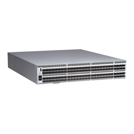
– One external USB Type A connector. License Options The Brocade G730 Switch uses a capacity-based Ports on Demand (POD) license method. Refer to the Brocade Fabric OS Software Licensing Guide for more details. Port-Side View of the Device The following figure shows the port-side view of the Brocade G730 Fibre Channel Switch. -
Page 10: Nonport-Side View Of The Device
Figure 2: Port Numbering for the Brocade G730 Switch Nonport-Side View of the Device The following figure shows the nonport-side view of the Brocade G730 Switch. Figure 3: Nonport-Side View with AC Power Supply and Fan Assembly Units 1. Power Supply Units (PSU 1 and PSU 2 from right to left) 2. - Page 11 ® G730-Install-IG100 Installation Guide Brocade G730 Switch Hardware Installation Guide Table 3: Management Options for the Device Management Tool Out-of-Band Support Reference Documents Command line interface (CLI) Ethernet or serial connection Brocade Fabric OS Administration Guide Up to two admin sessions and four user Brocade Fabric OS Command Reference Manual sessions simultaneously.
-
Page 12: Preparing For Installation
® G730-Install-IG100 Installation Guide Brocade G730 Switch Hardware Installation Guide Preparing for Installation Perform the following preliminary steps to ensure a successful installation: • Note the safety precautions to avoid harm to you or damage to the device. • Ensure that facility requirements are met. •... -
Page 13: Esd Precautions
® G730-Install-IG100 Installation Guide Brocade G730 Switch Hardware Installation Guide CAUTION Do not install the device in an environment where the operating ambient temperature might exceed 40°C (104°F). ESD Precautions DANGER For safety reasons, the ESD wrist strap should contain a series 1 megaohm resistor. CAUTION Before plugging a cable into any port, be sure to discharge the voltage stored on the cable by touching the electrical contacts to ground surface. -
Page 14: Lifting And Weight-Related Precautions
All fiber-optic interfaces use Class 1 lasers. DANGER Use only optical transceivers that are qualified by Broadcom and that comply with the FDA Class 1 radiation performance requirements defined in 21 CFR Subchapter I and with IEC 60825 and EN60825. Optical products that do not comply with these standards might emit light that is hazardous to the eyes. -
Page 15: Quick Installation Checklist
® G730-Install-IG100 Installation Guide Brocade G730 Switch Hardware Installation Guide • Through chassis rack ear mounts to a grounded data center rack. All equipment in the rack is grounded through a reliable branch circuit connection. • Through an explicit ground cable. The chassis is grounded through a ground cable using the threaded ground lug connection on the nonport side of the chassis. - Page 16 ® G730-Install-IG100 Installation Guide Brocade G730 Switch Hardware Installation Guide Preinstallation Tasks Review all installation requirements ahead of time as part of your site preparation. Careful planning and site preparation ensure seamless installation, especially when installing multiple devices. Table 5: Installation Prerequisites Task Task Details or Additional Information Completed...
- Page 17 ® G730-Install-IG100 Installation Guide Brocade G730 Switch Hardware Installation Guide Table 6: Installation and Basic System Configuration Task Task Details or Additional Information Completed Mount the device. Choose one of the following mounting options: • Mount the device as a stand-alone unit. See Installing the Device as a Stand-alone Unit.
-
Page 18: Shipping Carton Contents
® G730-Install-IG100 Installation Guide Brocade G730 Switch Hardware Installation Guide Task Task Details or Additional Information Completed • Check the LEDs to verify the operation of functional parts. See Interpreting Verify that the device operates Port-Side LEDs Interpreting Nonport-Side LEDs. correctly. -
Page 19: Mounting The Device
® G730-Install-IG100 Installation Guide Brocade G730 Switch Hardware Installation Guide Mounting the Device You can install the device in several ways: • As a stand-alone unit on a flat surface, for example, a table top. Use the rubber feet included with the shipment to secure the device on the surface. -
Page 20: Installing The Device As A Stand-Alone Unit
® G730-Install-IG100 Installation Guide Brocade G730 Switch Hardware Installation Guide Installing the Device as a Stand-alone Unit Perform the following steps to install the device as a stand-alone unit on a table: 1. Unpack the device and verify that the items listed under Shipping Carton Contents are present and undamaged. -
Page 21: Parts List
® G730-Install-IG100 Installation Guide Brocade G730 Switch Hardware Installation Guide The following items are required to install the device using the Universal Four-Post Rack Kit: • No. 2 Phillips torque screwdriver • 1/4-in. slotted-blade torque screwdriver Parts List The following parts are provided with the 1U and 2U Universal Four-Post Rack Kit (XBR-R000296): Figure 5: Universal Four-Post Rack Kit Parts 1. -
Page 22: Flush-Front Mounting
® G730-Install-IG100 Installation Guide Brocade G730 Switch Hardware Installation Guide 5. Bracket Extensions, Long (2) 6. Screw, 8-32 x 5/16-in. Panhead Phillips (8) 7. Screw, 8-32 x 5/16-in. Flathead Phillips (16) 8. Screw, 6-32 x 1/4-in. Panhead Phillips (8) 9. Screw, 10-32 x 5/8-in. Panhead Phillips (8) 10. -
Page 23: Attaching The Front Brackets
® G730-Install-IG100 Installation Guide Brocade G730 Switch Hardware Installation Guide Attaching the Front Brackets Perform the following steps to attach the front brackets to the device: 1. Position the right front bracket with the flat side against the right side of the device at the front of the device. 2. -
Page 24: Attaching The Extension Brackets To The Device
® G730-Install-IG100 Installation Guide Brocade G730 Switch Hardware Installation Guide Attaching the Extension Brackets to the Device Perform the following steps to attach the extension brackets to the device. You can use medium and long extension brackets for this task. 1. -
Page 25: Installing The Device In The Rack
® G730-Install-IG100 Installation Guide Brocade G730 Switch Hardware Installation Guide Installing the Device in the Rack Perform the following steps to install the device in the rack: 1. Position the device in the rack. Provide temporary support under the device as you secure the rail kit to the rack. 2. - Page 26 ® G730-Install-IG100 Installation Guide Brocade G730 Switch Hardware Installation Guide 4. Repeat Step 2 and 3 to attach the left rear bracket to the left extension bracket. 5. Adjust the brackets to the rack depth and tighten all 6-32 x 1/4-in. screws to a torque of 10 cm-kg (9 in.-lb). Figure 9: Attaching the Rear Brackets to the Extensions 1.
-
Page 27: Attaching The Rear Brackets To The Rack Posts
® G730-Install-IG100 Installation Guide Brocade G730 Switch Hardware Installation Guide Attaching the Rear Brackets to the Rack Posts Perform the following steps to attach the rear brackets to the rack posts: 1. Attach the right rear bracket to the right rear rack post using two 10-32 x 5/8-in. panhead screws and two retainer nuts. Use the upper and lower holes in the bracket. -
Page 28: Attaching The Front Brackets To The Rear Of The Device
® G730-Install-IG100 Installation Guide Brocade G730 Switch Hardware Installation Guide NOTE The illustrations in the rack installation procedures show a 1U device, but the instructions are the same for a 2U device. The illustrations in the rack installation procedures are for reference only and may not show the actual device. -
Page 29: Attaching The Extensions To The Front Of The Device
® G730-Install-IG100 Installation Guide Brocade G730 Switch Hardware Installation Guide Attaching the Extensions to the Front of the Device Perform the following steps to attach the extension brackets to the front of the device. You can use medium or long extension brackets for this task, depending on your rack depth. -
Page 30: Installing The Device In The Rack
® G730-Install-IG100 Installation Guide Brocade G730 Switch Hardware Installation Guide Installing the Device in the Rack Perform the following steps to install the device in the rack: 1. Position the device in the rack, providing temporary support under the device until the rail kit is secured to the rack. 2. - Page 31 ® G730-Install-IG100 Installation Guide Brocade G730 Switch Hardware Installation Guide 3. Attach the brackets using four 6-32 x 1/4-in. panhead screws. 4. Repeat Steps 2 and 3 to attach the left rear bracket to the left extension. 5. Adjust the brackets to the rack depth, and tighten all 6-32 x 1/4-in. screws to a torque of 10 cm-kg (9 in.-lb). Figure 14: Attaching the Rear Brackets to the Extensions at the Front of the Device 1.
- Page 32 ® G730-Install-IG100 Installation Guide Brocade G730 Switch Hardware Installation Guide Figure 15: Attaching the Short or Long Rear Brackets to the Extensions 1. Rear Bracket, Short or Long 2. Screws, 6-32 x 1/4-in. Panhead Phillips G730-Install-IG100...
-
Page 33: Attaching The Rear Brackets To The Front Rack Posts
® G730-Install-IG100 Installation Guide Brocade G730 Switch Hardware Installation Guide Attaching the Rear Brackets to the Front Rack Posts Perform the following steps to attach the rear brackets to the front rack posts: 1. Attach the right rear bracket to the right front rack post using two 10-32 x 5/8-in. screws and two retainer nuts. Use the upper and lower holes in the bracket. -
Page 34: Time And Items Required
® G730-Install-IG100 Installation Guide Brocade G730 Switch Hardware Installation Guide You can mount the device in a two-post rack in two ways: • With the port side flush with the front posts • With the posts mounted to the mid-section of the device Observe the following when mounting this device: •... -
Page 35: Flush-Front Mounting
® G730-Install-IG100 Installation Guide Brocade G730 Switch Hardware Installation Guide 5. Screw, 8-32 x 5/16-in. Flathead Phillips (16) 6. Screw, 6-32 x 1/4-in. Panhead Phillips (8) 7. Screw, 10-32 x 5/8-in. Panhead Phillips (8) 8. Retainer Nut, 10-32 (8) Ensure that the items listed and illustrated in the preceding figure are included in the kit. NOTE Not all parts may be used with certain installations depending on the device type. -
Page 36: Attaching The Front Brackets To The Device
® G730-Install-IG100 Installation Guide Brocade G730 Switch Hardware Installation Guide Attaching the Front Brackets to the Device Perform the following steps to attach the front brackets to the device: 1. Position the right front bracket with the flat side against the right side of the device. 2. -
Page 37: Attaching The Front Brackets To The Rack
® G730-Install-IG100 Installation Guide Brocade G730 Switch Hardware Installation Guide Attaching the Front Brackets to the Rack Perform the following steps to install the device in the rack: 1. Position the device in the rack, providing temporary support under the device until the rack kit is fully secured to the rack. -
Page 38: Attaching The Rear Brackets To The Rack
® G730-Install-IG100 Installation Guide Brocade G730 Switch Hardware Installation Guide Attaching the Rear Brackets to the Rack Perform the following steps to attach the rear brackets to the rack: 1. Select the proper length bracket for your post width. If your posts are 3 inches to 5 inches wide, use the brackets marked 3-5 INCH. -
Page 39: Attaching The Rear Brackets To The Device
® G730-Install-IG100 Installation Guide Brocade G730 Switch Hardware Installation Guide Attaching the Rear Brackets to the Device Perform the following steps to attach the rear brackets to the device: 1. Align the right rear bracket to the right rear of the device and use four 8-32 x 5/16-in. panhead screws to attach the bracket to the device. -
Page 40: Attaching The Front Brackets To The Device
® G730-Install-IG100 Installation Guide Brocade G730 Switch Hardware Installation Guide Attaching the Front Brackets to the Rack Attaching the Rear Brackets to the Rack Attaching the Rear Brackets to the Device Attaching the Front Brackets to the Device Perform the following steps to attach the front brackets to the device: 1. -
Page 41: Attaching The Front Brackets To The Rack
® G730-Install-IG100 Installation Guide Brocade G730 Switch Hardware Installation Guide Attaching the Front Brackets to the Rack Perform the following steps to install the front brackets to the rack: 1. Position the device in the rack, providing temporary support under the device until the rack kit is fully secured to the rack. -
Page 42: Attaching The Rear Brackets To The Rack
® G730-Install-IG100 Installation Guide Brocade G730 Switch Hardware Installation Guide Attaching the Rear Brackets to the Rack Perform the following steps to attach the rear brackets to the rack: 1. Select the proper length bracket for your post width. If your posts are 3 in. to 5 in. wide, use the brackets marked 3-5 INCH. -
Page 43: Attaching The Rear Brackets To The Device
® G730-Install-IG100 Installation Guide Brocade G730 Switch Hardware Installation Guide Attaching the Rear Brackets to the Device Perform the following steps to attach the rear brackets to the device: 1. Align the right rear bracket to the right rear of the device, and use four 8-32 x 5/16-in. panhead screws to attach the bracket to the device. -
Page 44: Initial Setup And Verification
PNY Attache 3.0 4 USB 32GB Flash Drive • PNY Attache 3.0 4 USB 16GB Flash Drive These drives are not orderable from Broadcom but are generically branded and can be purchased from other suppliers. Providing Power to the Device Perform the following steps to provide power to the device: 1. -
Page 45: Configuring The Ip Address
® G730-Install-IG100 Installation Guide Brocade G730 Switch Hardware Installation Guide If the serial port on the workstation is RJ-45 instead of RS-232, remove the adapter on the end of the serial cable and insert the exposed RJ-45 connector into the RJ-45 serial port on the workstation. 2. -
Page 46: Using Dhcp To Set The Ip Address
® G730-Install-IG100 Installation Guide Brocade G730 Switch Hardware Installation Guide Using DHCP to Set the IP Address When using DHCP, the switch obtains its IP address, subnet mask, and default gateway address from the DHCP server. The DHCP client can connect only to a DHCP server that is on the same subnet as the switch. If your DHCP server is not on the same subnet as the switch, use a static IP address. -
Page 47: Setting The Time Zone
® G730-Install-IG100 Installation Guide Brocade G730 Switch Hardware Installation Guide Thu Dec 22 15:06:00 UTC 2017 Setting the Time Zone The default time zone is Coordinated Universal Time (UTC). The time zone must be set only once because the value is stored in nonvolatile memory. -
Page 48: Customizing The Chassis Name And Switch Name
® G730-Install-IG100 Installation Guide Brocade G730 Switch Hardware Installation Guide Customizing the Chassis Name and Switch Name Changing the chassis and switch names is important for uniquely distinguishing and identifying the device and for accurate tracking of logs and errors. The messages that appear in the log are labeled with the switch name or chassis name, which makes tracking the errors much easier. -
Page 49: Verifying Correct Operation
® G730-Install-IG100 Installation Guide Brocade G730 Switch Hardware Installation Guide d) Enter a unique domain ID (such as the domain ID used by the previous switch, if still available). Domain: (1..239) [1] 3 e) Complete the remaining prompts or press Ctrl+D to accept the remaining settings without completing all the prompts. -
Page 50: Backing Up The Configuration
® G730-Install-IG100 Installation Guide Brocade G730 Switch Hardware Installation Guide (output truncated) The tempshow command shows the current temperature of the EM sensors. switch:admin> tempshow Sensor ID|Sensor Index|State |Centigrade |Fahrenheit | ------------------------------------------------------------- (output truncated) Backing Up the Configuration Back up the configuration regularly to ensure that a complete configuration is available for downloading to a replacement switch. -
Page 51: Installing Transceivers And Cables
All fiber-optic interfaces use Class 1 lasers. DANGER Use only optical transceivers that are qualified by Broadcom and that comply with the FDA Class 1 radiation performance requirements defined in 21 CFR Subchapter I and with IEC 60825 and EN60825. Optical products that do not comply with these standards might emit light that is hazardous to the eyes. -
Page 52: Installing An Sfp+ Transceiver
Brocade Transceiver Support Matrix and the Brocade Transceiver Modules webpage on www.broadcom.com. If you use an unqualified transceiver, the switchshow command output shows the port in a Mod_Inv state. The issue is also logged in the system error log. -
Page 53: Replacing An Sfp+ Transceiver
® G730-Install-IG100 Installation Guide Brocade G730 Switch Hardware Installation Guide 2. Position a cable so that the key (the ridge on one side of the cable connector) is aligned with the slot in the transceiver. Insert the cable into the transceiver until the latching mechanism clicks. Figure 27: Installing SFP+ Cables 1. -
Page 54: Installing An Sfp-Dd Transceiver
® G730-Install-IG100 Installation Guide Brocade G730 Switch Hardware Installation Guide Figure 28: Installing SFP+ Transceivers 1. Pull Tab of Transceiver in Upper Row 2. Pull Tab of Transceiver in Lower Row 4. Position a cable so that the key (the ridge on one side of the cable connector) is aligned with the slot in the transceiver. Insert the cable into the transceiver until the latching mechanism clicks. - Page 55 ® G730-Install-IG100 Installation Guide Brocade G730 Switch Hardware Installation Guide Perform the following steps to insert an SFP-DD transceiver and then insert the cables. NOTE • Always use the pull tab to insert or remove a transceiver, because the SFP-DD might be hot. •...
- Page 56 ® G730-Install-IG100 Installation Guide Brocade G730 Switch Hardware Installation Guide Figure 31: Orientation of the SFP-DD Connector 4. Hold the white push-pull boot, and push the connector straight into the port on the transceiver until the latching mechanism clicks. The connector will make two soft clicks as it enters the port, and the wide key will fit into the key slot on the SFP-DD transceiver.
-
Page 57: Replacing An Sfp-Dd Transceiver
® G730-Install-IG100 Installation Guide Brocade G730 Switch Hardware Installation Guide 5. Gently tug on the cable to make sure that it is seated firmly. Figure 33: SFP-DD Connectors Correctly Inserted Remove the second dust cap, and repeat Steps 3 through 5 to insert the second cable into the transceiver. Replacing an SFP-DD Transceiver NOTE Replacing an SFP-DD transceiver may cause disruption in the fabric or to the attached device. - Page 58 ® G730-Install-IG100 Installation Guide Brocade G730 Switch Hardware Installation Guide Figure 34: Installing SFP-DD Transceivers 1. SFP-DD Transceiver 2. Pull Tab of Transceiver in Lower Row 3. Dust Caps 4. Pull Tab of Transceiver in Upper Row 4. Remove the first dust cap from the transceiver. Leave the second dust cap in place. 5.
-
Page 59: Verifying The Operation Of New Transceivers
® G730-Install-IG100 Installation Guide Brocade G730 Switch Hardware Installation Guide 6. Hold the white push-pull boot, and push the connector straight into the port on the transceiver until the latching mechanism clicks. The connector makes two soft clicks as it enters the port, and the wide key fits into the key slot on the SFP-DD transceiver. -
Page 60: Monitoring The Device
Sometimes, the LEDs may flash any of the colors during boot, POST, or other diagnostic tests. This flashing is normal; it indicates a problem only if the LEDs indicate an unhealthy state after all boot processes and diagnostic tests are complete. Figure 38: Brocade G730 Port-Side LEDs 1. System Power LED 2. System Status LED 3. -
Page 61: System Power Led
® G730-Install-IG100 Installation Guide Brocade G730 Switch Hardware Installation Guide 9. DD (Lower) Ports 108 and 109 10. DD (Lower) Ports 108 and 109 Status LED System Power LED Use the following table to interpret the system power LED. Table 9: System Power LED Patterns during Normal Operation LED Color Hardware Status Recommended Action... -
Page 62: Fc Port (Sfp+) Status Leds
® G730-Install-IG100 Installation Guide Brocade G730 Switch Hardware Installation Guide Table 11: Management Port LED Patterns during Normal Operation LED Function/State Hardware Status Link/Speed—Green LED is on. 1000Mb/s link Link/Speed—LED is off. 100Mb/s link Activity—Green LED is blinking. Presence of activity FC Port (SFP+) Status LEDs Use the following table to interpret the FC port status LEDs. -
Page 63: Interpreting Nonport-Side Leds
Interpreting Nonport-Side LEDs The following figure shows the LEDs on the nonport side of the switch. Figure 39: Brocade G730 Nonport-Side LEDs 1. Power Supply DC Status LED 2. Power Supply AC Status LED 3. Fan Assembly Status LED... -
Page 64: Power Supply Leds
® G730-Install-IG100 Installation Guide Brocade G730 Switch Hardware Installation Guide Power Supply LEDs Use the following table to interpret the power supply LEDs during normal operation. Note that if both the AC and DC status LEDs are black/off, the power supply is off. Table 14: Nonport-Side LED Patterns during Normal Operation LED Name LED Color... -
Page 65: Interpreting Boot Results
® G730-Install-IG100 Installation Guide Brocade G730 Switch Hardware Installation Guide command or entering the diagDisablePost command to persistently disable the POST. The success or failure results of the diagnostic tests that run during the POST can be monitored through LED activity, the error log, or the command line interface. -
Page 66: Power Supply Assemblies
Power supply with nonport-side air exhaust. This unit moves the air from the port side to the nonport side of the device. • Power supply with nonport-side air intake. This unit moves the air from the nonport side to the port side of the device. Figure 40: Brocade G730 Power Supply Assembly 1. Power Supply #2 2. Grounding Screw 3. -
Page 67: Identifying The Direction Of The Power Supply Assembly Airflow
® G730-Install-IG100 Installation Guide Brocade G730 Switch Hardware Installation Guide DANGER If the installation requires a different power cord than the one supplied with the device, make sure you use a power cord displaying the mark of the safety agency that defines the regulations for power cords in your country. The mark is your assurance that the power cord can be used safely with the device. -
Page 68: Power Supply Assembly Task Guide
® G730-Install-IG100 Installation Guide Brocade G730 Switch Hardware Installation Guide • Check the power supply LEDs. See Power Supply LEDs to interpret the meaning of LED operation. • In Web Tools, click the Power Status icon. • Enter the psShow command at the prompt to display the power supply assembly status, as shown in the following example: Device:admin>... -
Page 69: Recording Critical Information About The Power Supply Assembly
® G730-Install-IG100 Installation Guide Brocade G730 Switch Hardware Installation Guide Recording Critical Information about the Power Supply Assembly You can use the following commands to record the power supply assembly configuration and operation information: • chassisshow • historyshow • psshow •... - Page 70 ® G730-Install-IG100 Installation Guide Brocade G730 Switch Hardware Installation Guide The new power supply assembly must have the same part number and airflow label (or lack thereof) as the power supply assembly already installed. 1. To leave the device in service while installing a power supply assembly, verify that the other power supply assembly (the one already installed) has been powered on for at least 4 seconds and has a steady green LED.
-
Page 71: Fan Assemblies
® G730-Install-IG100 Installation Guide Brocade G730 Switch Hardware Installation Guide Fan Assemblies The fan assembly units in the chassis can be removed and replaced without special tools. The device can continue operating during the replacement. The device supports the following types of fan assemblies: •... -
Page 72: Precautions Specific To The Fan Assemblies
® G730-Install-IG100 Installation Guide Brocade G730 Switch Hardware Installation Guide Precautions Specific to the Fan Assemblies CAUTION Disassembling any part of the power supply and fan assembly voids the warranty and regulatory certifications. There are no user-serviceable parts inside the power supply and fan assembly. CAUTION Ensure that the airflow direction of the power supply unit matches that of the installed fan tray. -
Page 73: Fan Assembly Task Guide
® G730-Install-IG100 Installation Guide Brocade G730 Switch Hardware Installation Guide Fan Assembly Task Guide You can perform a set of steps to install or replace a fan assembly or to replace two or all three fan assemblies. By default, all three fan assemblies are installed in the device. Replacing a Fan Assembly (Hot-Swap) If your device is up and running with three fan assemblies, but one of them has failed, perform the following steps: 1. -
Page 74: Removing A Fan Assembly
® G730-Install-IG100 Installation Guide Brocade G730 Switch Hardware Installation Guide Removing a Fan Assembly Perform the following steps to remove a faulty fan assembly: 1. To leave the device in service while removing a fan assembly, verify that the other power supplies and fan assemblies (the ones not being replaced) have been powered on for at least 4 seconds and have a steady green LED. -
Page 75: Verifying The Operation Of The Power Supply And Fan Assemblies
® G730-Install-IG100 Installation Guide Brocade G730 Switch Hardware Installation Guide Figure 45: Inserting a Fan Assembly 1. Fan Assembly Unit 2. Fan Assembly Handle 4. Gently push the fan assembly into the chassis until it is firmly seated. 5. Using the Phillips screwdriver, secure the fan assembly to the chassis by tightening the captive screw. 6. -
Page 76: Technical Specifications
® G730-Install-IG100 Installation Guide Brocade G730 Switch Hardware Installation Guide Technical Specifications The following tables highlight the features and specifications for the Brocade G730 Switch. System Specifications System Component Description Enclosure 2U, power from the back of the switch. •... - Page 77 Empty weight refers to the device with two power supply and fan assemblies that are installed without any SFP+ or SFP- DD transceivers. Weight (Fully Model Height Width Depth Weight (Empty) Loaded) Brocade G730 8.67 cm (3.41 in.) 44.00 cm (17.32 in.) 60.96 cm (24.00 in.) 18.92 kg (41.7 lb) 21.48 kg (47.35 lb) Switch Environmental Requirements Condition...
- Page 78 (range) (range) Data Port Specifications (Fibre Channel) Model Name Port Numbers Media Type Description Brocade G730 0 to 95 8, 10, 16, 32, or 64G SFP+ optical ports Can be an F_Port, E_Port, EX_Port, D_Port, or Switch AE_Port. 96 to 127...
- Page 79 ® G730-Install-IG100 Installation Guide Brocade G730 Switch Hardware Installation Guide Cable Size Extended Long Port Speed (G) Short Wavelength (SWL) Long Wavelength (LWL) (Microns) Wavelength (ELWL) 70m (230 ft) (OM3) 100m (328 ft) (OM4) 62.5 10 km (6.2 miles) 25 km (15.5 miles) 70m (230 ft) (OM3) 100m (328 ft) (OM4 and OM5) 62.5...
-
Page 80: Regulatory Statements
® G730-Install-IG100 Installation Guide Brocade G730 Switch Hardware Installation Guide Regulatory Statements This section contains regulatory compliance statements for your device. BSMI Statement (Taiwan) Warning: This is a Class A product. In a domestic environment, this product may cause radio interference, in which case the user may be required to take adequate measures. -
Page 81: China Ccc Statement
® G730-Install-IG100 Installation Guide Brocade G730 Switch Hardware Installation Guide China CCC Statement G730-Install-IG100... -
Page 82: China Rohs
® G730-Install-IG100 Installation Guide Brocade G730 Switch Hardware Installation Guide China ROHS FCC Warning (U.S. Only) This equipment has been tested and complies with the limits for a Class A computing device pursuant to Part 15 of the FCC rules. These limits are designed to provide reasonable protection against harmful interference when the equipment is operated in a commercial environment. -
Page 83: Taiwan Rohs Certification
® G730-Install-IG100 Installation Guide Brocade G730 Switch Hardware Installation Guide Taiwan ROHS Certification VCCI Statement G730-Install-IG100... -
Page 84: Regulatory Compliance
® G730-Install-IG100 Installation Guide Brocade G730 Switch Hardware Installation Guide This is a Class A product based on the standard of the Voluntary Control Council for Interference by Information Technology Equipment (VCCI). If this equipment is used in a domestic environment, radio disturbance might arise. When such trouble occurs, the user might be required to take corrective actions. -
Page 85: Cautions And Danger Notices
® G730-Install-IG100 Installation Guide Brocade G730 Switch Hardware Installation Guide Cautions and Danger Notices This section contains translations of safety notices for your product. Cautions A Caution statement alerts you to situations that can be potentially hazardous to you or cause damage to hardware, firmware, software, or data. - Page 86 ® G730-Install-IG100 Installation Guide Brocade G730 Switch Hardware Installation Guide PRECAUCIÓN Asegúrese de que el flujo de aire en las inmediaciones de las partes anterior, laterales y posterior del instrumento no esté restringido. Electrical Cautions CAUTION Before plugging a cable into any port, be sure to discharge the voltage stored on the cable by touching the electrical contacts to ground surface.
- Page 87 ® G730-Install-IG100 Installation Guide Brocade G730 Switch Hardware Installation Guide CAUTION The power supply switch must be in the off position when you insert the power supply into the chassis. Damage to the switch can result if a live power supply is installed. VORSICHT Der Schalter des Netzteils muss in der Stellung „Aus“...
-
Page 88: Danger Notices
® G730-Install-IG100 Installation Guide Brocade G730 Switch Hardware Installation Guide CAUTION For a DC system, use grounding wire of at least 16 AWG. The grounding wire should be attached to the DC input connector; the other end connects to the building ground. VORSICHT Für ein Gleichstromsystem verwenden Erdungskabel von mindestens 16 AWG (1.31 mm2) (amerikanische Norm für Drahtquerschnitte). - Page 89 ® G730-Install-IG100 Installation Guide Brocade G730 Switch Hardware Installation Guide DANGER Be careful not to accidently insert your fingers into the fan tray while removing it from the chassis. The fan may still be spinning at a high speed. GEFAHR Die Finger dürfen nicht versehentlich in das Ventilatorblech gesteckt werden, wenn dieses vom Gehäuse abgenommen wird.
- Page 90 ® G730-Install-IG100 Installation Guide Brocade G730 Switch Hardware Installation Guide DANGER To avoid high voltage shock, do not open the device while the power is on. GEFAHR Das eingeschaltete Gerät darf nicht geöffnet werden, da andernfalls das Risiko eines Stromschlags mit Hochspannung besteht.
- Page 91 G730 Switch Hardware Installation Guide DANGER Use only optical transceivers that are qualified by Broadcom and that comply with the FDA Class 1 radiation performance requirements defined in 21 CFR Subchapter I and with IEC 60825 and EN60825. Optical products that do not comply with these standards might emit light that is hazardous to the eyes.
-
Page 92: Revision History
® G730-Install-IG100 Installation Guide Brocade G730 Switch Hardware Installation Guide Revision History G730-Install-IG100; 15 December 2021 Initial document version. G730-Install-IG100... -
Page 93: Copyright Statement
All trademarks, trade names, service marks, and logos referenced herein belong to their respective companies. Broadcom reserves the right to make changes without further notice to any products or data herein to improve reliability, function, or design. Information that is furnished by Broadcom is believed to be accurate and reliable. However, Broadcom does not assume any liability arising out of the application or use of this information, nor the application or use of any product or circuit described herein, neither does it convey any license under its patent rights nor the rights of others.
Need help?
Do you have a question about the Brocade G730 and is the answer not in the manual?
Questions and answers