
Related Manuals for Broadcom Brocade G630


Summary of Contents for Broadcom Brocade G630
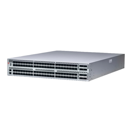
- Page 1 HARDWARE INSTALLATION GUIDE Brocade G630 Hardware Installation Guide 53-1005235-02 29 December 2017...
- Page 2 Broadcom. The term "Broadcom" refers to Broadcom Limited and/or its subsidiaries Brocade, a Broadcom Limited Company, reserves the right to make changes without further notice to any products or data herein to improve reliability, function, or design.
-
Page 3: Table Of Contents
Time and items required..........................................38 Parts list................................................38 Flush-front mounting........................................... 39 Mid-mounting..............................................43 Initial Setup and Verification......................................49 Items required................................................49 Providing power to the device........................................... 49 Establishing a first-time serial connection....................................50 Configuring the IP address..........................................51 Brocade G630 Hardware Installation Guide 53-1005235-02... - Page 4 Time and items required............................................77 Recording power supply assembly critical information................................77 Removing a power supply and fan assembly..................................... 78 Inserting a new power supply assembly......................................79 Verifying the operation of the power supply and fan assemblies............................80 Brocade G630 Hardware Installation Guide 53-1005235-02...
- Page 5 Recording power supply and fan assembly critical information............................85 Removing a fan assembly...........................................86 Inserting a new fan assembly..........................................86 Verifying the operation of the power supply and fan assemblies............................87 Brocade G630 Technical Specifications..................................89 System specifications............................................89 Fibre Channel................................................89 Other.................................................... 90 LEDs.....................................................90...
- Page 6 Dangers related to equipment weight....................................103 Laser dangers.............................................. 103 Cautions................................................... 103 General cautions............................................103 ....................................................104 Electrical cautions............................................104 Brocade G630 Hardware Installation Guide 53-1005235-02...
-
Page 7: About This Document
Document feedback......................................9 Supported hardware and software The Brocade G630 FC switch is introduced in Fabric OS 8.2.0 software release. The following tables list the power supply and fan assemblies, and rack mount kits supported on this device. TABLE 1 Power supply and fan assemblies... -
Page 8: Text Formatting Conventions
Repeat the previous element, for example, member[member...]. Indicates a “soft” line break in command examples. If a backslash separates two lines of a command input, enter the entire command at the prompt without the backslash. Brocade G630 Hardware Installation Guide 53-1005235-02... -
Page 9: Document Feedback
However, if you find an error or an omission, or you think that a topic needs further development, we want to hear from you. Send your feedback documentation.pdl@broadcom.com Provide the publication title, part number, and as much detail as possible, including the topic heading and page number if applicable, as well as your suggestions for improvement. Brocade G630 Hardware Installation Guide 53-1005235-02... - Page 10 Brocade G630 Hardware Installation Guide 53-1005235-02...
-
Page 11: Device Overview
• Nonport-side view......................................13 • Device management options..................................14 Hardware features The Brocade G630 offers the following features and capabilities: • Up to 96 auto-sensing ports supporting high-performance 32-Gbps SFP+ ports technology in a single domain with NVMe support on egress-only. •... -
Page 12: License Options
License options The Brocade G630 uses a capacity-based Ports on Demand (POD) license method. An Integrated Routing (IR) license is required to enable EX_Port functionality on this device. Refer to the Brocade Fabric OS Software Licensing Guide for more details. -
Page 13: Nonport-Side View
QSFP port 5 ( FC ports 116 - 117 - 118 - 119 ) QSFP port 7 ( FC ports 124 - 125 - 126 - 127 ) Nonport-side view The following illustration shows the nonport-side view of the Brocade G630 FC switch. Brocade G630 Hardware Installation Guide 53-1005235-02... -
Page 14: Device Management Options
Management Server Ethernet or serial connection Brocade Fabric OS Administration Guide Brocade Fabric OS Command Reference Brocade Network Advisor (BNA) Ethernet or serial connection Brocade Network Advisor documentation set BNA must be purchased separately. Brocade G630 Hardware Installation Guide 53-1005235-02... -
Page 15: Preparing For The Installation
"E", or an orange arrow with an "I." CAUTION Never leave tools inside the chassis. CAUTION To protect the serial port from damage, keep the cover on the port when not in use. Brocade G630 Hardware Installation Guide 53-1005235-02... -
Page 16: Esd Precautions
Remove both power cords before servicing. DANGER Disconnect the power cord from all power sources to completely remove power from the device. DANGER To avoid high voltage shock, do not open the device while the power is on. Brocade G630 Hardware Installation Guide 53-1005235-02... -
Page 17: Lifting And Weight-Related Precautions
CAUTION To prevent damage to the chassis and components, never attempt to lift the chassis using the fan or power supply handles. These handles were not designed to support the weight of the chassis. Brocade G630 Hardware Installation Guide 53-1005235-02... -
Page 18: Laser Precautions
Pre-installation tasks Review all installation requirements ahead of time as part of your site preparation. Careful planning and site preparation ensures seamless installation, especially when installing multiple devices. Brocade G630 Hardware Installation Guide 53-1005235-02... -
Page 19: Installation And Initial Configuration
Attach a management station, establish a Refer to Establishing a first-time serial connection on page 50. After completing this serial connection, and change the default task, log in to the serial port to configure the device. passwords (optional). Brocade G630 Hardware Installation Guide 53-1005235-02... -
Page 20: Shipping Carton Contents
An accessory kit containing the following items: – A serial cable – Two 6-ft. power cords – Power cord retainer clips – Rubber feet. – China-RoHS Hazardous/Toxic Substance statement – Network Advisor web pointer card. – EZSwitch web pointer card Brocade G630 Hardware Installation Guide 53-1005235-02... - Page 21 Shipping carton contents – Brocade documentation web pointer card • Inner foam Brocade G630 Hardware Installation Guide 53-1005235-02...
- Page 22 Brocade G630 Hardware Installation Guide 53-1005235-02...
-
Page 23: Mounting The Device
CAUTION To prevent damage to the chassis and components, never attempt to lift the chassis using the fan or power supply handles. These handles were not designed to support the weight of the chassis. Brocade G630 Hardware Installation Guide 53-1005235-02... -
Page 24: Standalone Installation
Observe the following when mounting this device: • Two people are required to install the device in a rack. One person holds the device, while the other screws in the front and rear brackets. Brocade G630 Hardware Installation Guide 53-1005235-02... -
Page 25: Time And Items Required
The following items are required to install the device using the Universal Four-Post Rack Kit: • #2 Phillips torque screwdriver • 1/4-inch slotted-blade torque screwdriver Parts list The following parts are provided wit the 1U, 1.5U, and 2U Universal Kit for Four Post Racks Installation (XBR-R000296). Brocade G630 Hardware Installation Guide 53-1005235-02... - Page 26 Ensure that the items listed and illustrated are included in the kit. Note that not all parts may be used with certain installations depending on the device type. CAUTION Use the screws specified in the procedure. Using longer screws can damage the device. Brocade G630 Hardware Installation Guide 53-1005235-02...
-
Page 27: Flush-Front Mounting
Use the upper and lower screw holes, leaving the center holes empty. Repeat step 1 and step 2 to attach the left front bracket to the left side of the device. Brocade G630 Hardware Installation Guide 53-1005235-02... - Page 28 Use the upper and lower screw holes, leaving the center holes empty. Repeat step 2 and step 3 to attach the left bracket extension to the left side of the device. Brocade G630 Hardware Installation Guide 53-1005235-02...
- Page 29 Attach the left front bracket to the left front rack post using two 10-32 x 5/8-in. panhead screws and two retainer nuts. Use the upper and lower holes in the bracket. Brocade G630 Hardware Installation Guide 53-1005235-02...
- Page 30 Attach the brackets using four 6-32 x 1/4-in. panhead screws. If possible, leave at least one empty vertical pair of holes between the screws for better support. Repeat step 2 and 3 to attach the left rear bracket to the left bracket extension. Brocade G630 Hardware Installation Guide 53-1005235-02...
- Page 31 8. Use the upper and lower holes in the bracket. Attach the left rear bracket to the left rear rack post using two 10-32 x 5/8-in. panhead screws and two retainer nuts. Use the upper and lower holes in the bracket. Brocade G630 Hardware Installation Guide 53-1005235-02...
-
Page 32: Flush-Rear (Recessed) Mounting
Installing the device in the rack on page 34 Attaching the rear brackets to the extensions at the front of the device on page 35 Attaching the rear brackets to the front rack posts on page 37 Brocade G630 Hardware Installation Guide 53-1005235-02... - Page 33 Insert four 8-32 x 5/16-in. flathead screws through the vertically aligned holes in the bracket extension and then into the holes on the side of the device. Use the upper and lower screw holes, leaving the center holes empty. Brocade G630 Hardware Installation Guide 53-1005235-02...
- Page 34 Attach the left front bracket to the left rear rack post using two 10-32 x 5/8-in. panhead screws and two retainer nuts. Use the upper and lower holes in the bracket. Brocade G630 Hardware Installation Guide 53-1005235-02...
- Page 35 Attach the brackets using four 6-32 x 1/4-in. panhead screws. Repeat step 2 and step 3 to attach the left rear bracket to the left extension. Brocade G630 Hardware Installation Guide 53-1005235-02...
- Page 36 FIGURE 12 Attaching the rear brackets to the extensions at the front of the device Rear brackets, short Screws, 6-32 x 1/4-in., panhead Phillips FIGURE 13 Attaching the short or long rear brackets to the extensions Brocade G630 Hardware Installation Guide 53-1005235-02...
-
Page 37: Installing The Universal Two-Post Rack Kit (Xbr-R000294)
There are two ways you can mount the device in a two-post rack: • With the port side flush with the front posts • With the posts mounted to the mid-section of the device Brocade G630 Hardware Installation Guide 53-1005235-02... -
Page 38: Time And Items Required
Rear brackets, 3-5 inch post (2) Screw, 6-32 x 1/4-in., panhead Phillips (8) Rear brackets, 5-6 inch post (2) Screw, 10-32 x 5/8-in., panhead Phillips (8) Screw, 8-32 x 5/16-in., panhead Phillips (8) Retainer nut, 10-32 (8) Brocade G630 Hardware Installation Guide 53-1005235-02... -
Page 39: Flush-Front Mounting
Use the upper and lower screw holes, leaving the center holes empty. Repeat step 1 and step 2 to attach the left front bracket to the left side of the device. Brocade G630 Hardware Installation Guide 53-1005235-02... - Page 40 Attach the left front bracket to the left rack upright using two 10-32 x 5/8-in. panhead screws and two retainer nuts. Use the upper and lower holes in the bracket. Brocade G630 Hardware Installation Guide 53-1005235-02...
- Page 41 Attach the bracket to the right rack upright using two 10-32 x 5/8-in. panhead screws and two retainer nuts. Use the upper and lower holes in the bracket. Repeat step 2 and step 3 to attach the left rear bracket to the left rack upright. Brocade G630 Hardware Installation Guide 53-1005235-02...
- Page 42 Align the left rear bracket to the left rear of the device and use four 8-32 x 5/16-in. panhead screws to attach the bracket to the device. Again, use the upper and lower slots in the bracket. Brocade G630 Hardware Installation Guide 53-1005235-02...
-
Page 43: Mid-Mounting
Attaching the front brackets to the device Complete the following steps to attach the front brackets to the device. Position the right front bracket with the flat side against the right side of the device, as shown in Figure Brocade G630 Hardware Installation Guide 53-1005235-02... - Page 44 Attach the left front bracket to the left rack upright using two 10-32 x 5/8-in. screws and two retainer nuts. Use the upper and lower holes in the bracket. Brocade G630 Hardware Installation Guide 53-1005235-02...
- Page 45 Attach the brackets to the right rack upright using two 10-32 x 5/8-in. panhead screws and two retainer nuts. Repeat step 2 and step 3 to attach the left rear bracket to the left rack upright. Brocade G630 Hardware Installation Guide 53-1005235-02...
- Page 46 Align the left rear bracket to the left rear of the device and use four 8-32 x 5/16-in. panhead screws to attach the bracket to the device. Again, use the upper and lower slots in the bracket. Brocade G630 Hardware Installation Guide 53-1005235-02...
- Page 47 Installing the Universal Two-Post Rack Kit (XBR-R000294) Tighten all the 8-32 x 5/16-in. screws to a torque of 15 in-lb (17 cm-kg). FIGURE 23 Attaching the rear brackets to the device Screws, 8-32 x 5/16-in., panhead Phillips Brocade G630 Hardware Installation Guide 53-1005235-02...
- Page 48 Brocade G630 Hardware Installation Guide 53-1005235-02...
-
Page 49: Initial Setup And Verification
After POST is complete, verify that the switch power and switch status LEDs are green. For more information about how to interpret POST, BOOT, and diagnostics tests, refer to Monitoring the Device on page 65. Brocade G630 Hardware Installation Guide 53-1005235-02... -
Page 50: Establishing A First-Time Serial Connection
Initial passwords can be 8 to 40 characters long. They must begin with an alphabetic character. They can include numeric characters, the period (.), and the underscore (_) only. Passwords are case-sensitive, and they are not displayed when you enter them on the command line. Brocade G630 Hardware Installation Guide 53-1005235-02... -
Page 51: Configuring The Ip Address
You can synchronize the local time of the principal or primary fabric configuration server (FCS) device to that of an external Network Time Protocol (NTP) server. Perform the following steps to set the date and time. Log in to the device as admin. Brocade G630 Hardware Installation Guide 53-1005235-02... -
Page 52: Setting The Time Zone
-5,0 Eastern Daylight -4,0 Central Standard -6,0 Central Daylight -5,0 Mountain Standard -7,0 Mountain Daylight -6,0 Pacific Standard -8,0 Pacific Daylight -7,0 Alaskan Standard -9,0 Alaskan Daylight -8,0 Hawaiian Standard -10,0 Reboot the device. Brocade G630 Hardware Installation Guide 53-1005235-02... -
Page 53: Synchronizing Local Time With An External Source
At this point, the device can be accessed remotely, using either command line or Brocade Web Tools. Ensure that the device is not being modified from any other connections during the remaining tasks in this chapter. The Ethernet management port also supports Auto MDI/MDIX. Brocade G630 Hardware Installation Guide 53-1005235-02... -
Page 54: Setting The Domain Id
Complete the remaining prompts or press Ctrl+D to accept the remaining settings without completing all the prompts. Re-enable the switch by entering the switchEnable command. Verifying correct operation Perform the following steps to verify correct operation of the device. Check the LEDs to verify that all components are functional. Brocade G630 Hardware Installation Guide 53-1005235-02... - Page 55 460800 No_Module 460900 No_Module 460a00 No_Module 460b00 No_Module 460c00 No_Module 460d00 No_Module 460e00 No_Module 460f00 No_Module 461000 No_Module 461100 No_Module 461200 No_Module 461300 No_Module 461400 No_Module 461500 No_Module 461600 No_Module 461700 No_Module <Output truncated> Brocade G630 Hardware Installation Guide 53-1005235-02...
-
Page 56: Backing Up The Configuration
Power off both power supplies by setting each power switch to the “O” position. Unplug the power cables from the power source before servicing the device or FRUs. All devices are returned to their initial state the next time the switch is powered on. Brocade G630 Hardware Installation Guide 53-1005235-02... -
Page 57: Installing Transceivers And Cables
Many Brocade switches, backbones, and directors come with a transceiver extraction tool and holster. The extraction tool is designed to remove transceivers from modules where the space is limited. If you did not receive this tool with your product, you can order it from Brocade using part number XBR-48000-R0129. Brocade G630 Hardware Installation Guide 53-1005235-02... -
Page 58: Precautions Specific To Transceivers And Cables
The minimum bend radius for a 50 micron cable is 2 inches under full tensile load and 1.2 inches with no tensile load. Cables can be organized and managed in a variety of ways, for example, using cable channels on the sides of the rack or patch panels to minimize cable management. Follow these recommendations: Brocade G630 Hardware Installation Guide 53-1005235-02... -
Page 59: Installing An Sfp+ Transceiver
The device supports only Brocade-qualified transceivers. If you use an unqualified transceiver, the switchshow command output shows the port in a Mod_Inv state. Fabric OS also logs the issue in the system error log. To insert an SFP+ transceiver, complete the following steps: Brocade G630 Hardware Installation Guide 53-1005235-02... -
Page 60: Replacing An Sfp+ Transceiver
Do not insert any unsupported cable intended for an other type of transceiver into a regular SFP+ transceiver. You may damage the cable as well as the transceiver. Replacing an SFP+ transceiver Complete the following steps to remove and then install a new SFP+ transceiver. Brocade G630 Hardware Installation Guide 53-1005235-02... - Page 61 Cables are keyed so that they can be inserted in only one way. If a cable does not slide in easily, ensure that it is correctly oriented. Brocade G630 Hardware Installation Guide 53-1005235-02...
-
Page 62: Installing A Qsfp Transceiver
Do not insert any unsupported cable intended for an other type of transceiver into a regular QSFP transceiver. You may damage the cable as well as the transceiver. Replacing a QSFP transceiver Complete the following steps to remove and then install a new QSFP transceiver. Brocade G630 Hardware Installation Guide 53-1005235-02... -
Page 63: Verifying The Operation Of New Transceivers
Cables are keyed so that they can be inserted in only one way. If a cable does not slide in easily, ensure that it is correctly oriented. Verifying the operation of new transceivers You can use the following commands to verify if the transceivers are working correctly: • sfpShow • switchShow • errDump • fabricShow Brocade G630 Hardware Installation Guide 53-1005235-02... - Page 64 Verifying the operation of new transceivers Refer to the Brocade Fabric OS Command Reference for output examples and descriptions. Brocade G630 Hardware Installation Guide 53-1005235-02...
-
Page 65: Monitoring The Device
LEDs may flash either of the colors during boot, POST, or other diagnostic tests. This is normal; it does not indicate a problem unless the LEDs do not indicate a healthy state after all boot processes and diagnostic tests are complete. Brocade G630 Hardware Installation Guide 53-1005235-02... -
Page 66: System Power Led
Interpreting port-side LEDs FIGURE 29 Brocade G630 port-side LEDs System status LED 11. FC port 99 (QSFP 0) status LED System power LED 12. FC port 119 (QSFP 5) status LED SFP+ (upper) port 1 13. FC port 118 (QSFP 5) status LED SFP+ (upper) port 1 status LED 14. -
Page 67: System Status Led
Verify that the correct device is attached to the second) loopback cable or incompatible device switch. connection. Fast-flashing green (on 1/4 second; then off Port is online and an internal loopback No action required. 1/4 second) diagnostic test is running. Brocade G630 Hardware Installation Guide 53-1005235-02... -
Page 68: Qsfp Port Status Led
For the QSFP ports, if the port is configured as individual SFP+ FC ports on the other end using break-out cables, then the four individual port status LEDs for each QSFP should be monitored. Brocade G630 Hardware Installation Guide 53-1005235-02... -
Page 69: Interpreting Nonport-Side Leds
TABLE 17 Fan assembly status LED patterns during normal operation LED color Description Action required No light Fan assembly is not receiving power. Verify that the fan FRU is seated correctly. Steady green Fan assembly is operating normally. No action required. Brocade G630 Hardware Installation Guide 53-1005235-02... -
Page 70: Interpreting The Post Results
• Replace the faulty fan assembly. NOTE The Brocade G630 device requires minimum of two fan assemblies to be functional. Up to one fan assembly failure is supported. Interpreting the POST results Each time the switch is powered on, rebooted, or reset, the switch performs a power-on self-test (POST). Total boot time with the POST can be several minutes. -
Page 71: Running Diagnostic Tests
Diagnostic tests are run at supported link speeds depending on the speed of the link being tested and the type of port. NOTE Diagnostic tests may temporarily lock the transmit and receive speed of the links during diagnostic testing. Brocade recommends that you power-cycle the device after completing offline diagnostics tests. Brocade G630 Hardware Installation Guide 53-1005235-02... - Page 72 Brocade G630 Hardware Installation Guide 53-1005235-02...
-
Page 73: Power Supply Assemblies
Verifying the operation of the power supply and fan assemblies....................80 Power supply assemblies overview The power supply assembly units in the Brocade G630 chassis can be removed and replaced without special tools. The device can continue operating during the replacement. - Page 74 The power supply assembly units are hot-swappable if they are replaced one at a time. They are identical and fit into either slot. NOTE The device can operate all the ports with one power supply assembly unit if you do not require redundancy. Each power supply unit has one internal fan. Brocade G630 Hardware Installation Guide 53-1005235-02...
-
Page 75: Precautions Specific To The Power Supply Assemblies
Intake power supply and fan assembly with an orange "I" label or without any label: Pulls air from the nonport-side of the switch and exhausts it out the port side. – Nonport-side air intake – Port-side air exhaust – Back-to-front (nonport-side to port-side) airflow – Part numbers ending with -R Brocade G630 Hardware Installation Guide 53-1005235-02... -
Page 76: Power Supply Ok And Fail Status Leds
You can perform an easy set of steps to install or replace a power supply assembly or to replace both power supply assemblies. By default, both of the power supply assemblies are installed in the device. Brocade G630 Hardware Installation Guide 53-1005235-02... -
Page 77: Installing An Additional Power Supply And Fan Assembly (Hot-Install)
New power supply assembly (must have the same airflow direction as the power supply assembly being replaced) • #1 Phillips-head screwdriver Recording power supply assembly critical information You can use the following commands to record the power supply assembly configuration and operations information: • chassisshow Brocade G630 Hardware Installation Guide 53-1005235-02... -
Page 78: Removing A Power Supply And Fan Assembly
Push the lever on the lower right corner of the power supply unit towards the IEC socket. Remove the power supply assembly from the chassis by pulling the handle out and away from the chassis. Brocade G630 Hardware Installation Guide 53-1005235-02... -
Page 79: Inserting A New Power Supply Assembly
Power supply assembly handle Gently push the power supply assembly into the chassis until it is firmly seated. Plug the power cord into the power supply assembly and power is provided to the device immediately. Brocade G630 Hardware Installation Guide 53-1005235-02... -
Page 80: Verifying The Operation Of The Power Supply And Fan Assemblies
You can use the following commands to verify that the power supply and fan assemblies are operational: • psShow • fanShow • switchShow • errDump Refer to the Fabric OS Command Reference for output examples and descriptions. Brocade G630 Hardware Installation Guide 53-1005235-02... -
Page 81: Fan Assemblies
Verifying the operation of the power supply and fan assemblies....................87 Fan assemblies overview The fan assembly units in the Brocade G630 chassis can be removed and replaced without special tools. The device can continue operating during the replacement. The device supports the following types of fan assemblies. - Page 82 The device fans are fixed inside the fan assemblies to provide necessary airflow to cool the whole system. There are two fans located in each unit. The system software sets fan speed and measures fan speed through the tachometer interface. Brocade G630 Hardware Installation Guide 53-1005235-02...
-
Page 83: Precautions Specific To The Fan Assemblies
Port-side air intake – Front-to-back (port-side to nonport-side) airflow – Part numbers ending with -F Fan assembly status LED Refer to the following table to interpret the fan assembly status LED during normal operation Brocade G630 Hardware Installation Guide 53-1005235-02... -
Page 84: Fan Assembly Unit Fault Indicators
• Replace the faulty fan assembly. NOTE The Brocade G630 device requires minimum of two fan assemblies to be functional. Up to one fan assembly failure is supported. Fan assembly unit fault indicators Use one of the following methods to determine the status of the fan assemblies: •... -
Page 85: Replacing More Than One Fan Assemblies (Cold-Swap)
You can use the following commands to record the power supply and fan assembly configuration and operations information: • chassisshow • fanshow • psshow • historyshow • tempshow • sensorshow Refer to the Fabric OS Command Reference for output examples and descriptions. Brocade G630 Hardware Installation Guide 53-1005235-02... -
Page 86: Removing A Fan Assembly
LED. Using a Phillips screwdriver, unscrew the captive screw of the filler panel that is located in the empty fan assembly slot. Brocade G630 Hardware Installation Guide 53-1005235-02... -
Page 87: Verifying The Operation Of The Power Supply And Fan Assemblies
You can use the following commands to verify that the power supply and fan assemblies are operational: • psShow • fanShow • switchShow • errDump Refer to the Fabric OS Command Reference for output examples and descriptions. Brocade G630 Hardware Installation Guide 53-1005235-02... - Page 88 Brocade G630 Hardware Installation Guide 53-1005235-02...
-
Page 89: Brocade G630 Technical Specifications
Brocade G630 Technical Specifications This document highlights the features and specifications for the Brocade G630 switch. System specifications System component Description Enclosure 2U, power from back • Front-to-back airflow/nonport-side exhaust • Back-to-front airflow/nonport-side intake Power inlet Power supplies Dual, hot-swappable redundant power supplies with integral cooling fans... -
Page 90: Other
Weight (fully loaded) Brocade G630 switch 8.67 cm 44.00 cm 60.96 cm 19.05 kg 21.31 kg 3.41 inches 17.32 inches 24.00 inches 42.00 lbs 47.00 lb (With 2 PSUs and 3 (With all the Fans) transceivers) Brocade G630 Hardware Installation Guide 53-1005235-02... -
Page 91: Environmental Requirements
90 – 264 VAC (range) Do not repeat plug-in and plug-out operations within a short time, or else the internal inrush current limiting device (NTC) may not sufficiently cool down and may result in excessive inrush current. Brocade G630 Hardware Installation Guide 53-1005235-02... -
Page 92: Power Consumption (Typical Configuration)
Gbps (128 Gbps) QSFP optical ports Fibre Channel data transmission ranges Port speed (Gbps) Cable size (microns) Short wavelength (SWL) Long wavelength (LWL) Extended long wavelength (ELWL) 150 m (492 ft) (OM2) 380 m (1,264 ft) (OM3) Brocade G630 Hardware Installation Guide 53-1005235-02... -
Page 93: Serial Port Specifications (Pinout Rj-45)
Not supported Not supported Transmit data (output from G630) Logic ground Logic ground Receive data (input into G630) Not supported Not supported NOTE These specifications are for the serial connector on Brocade platforms only. Brocade G630 Hardware Installation Guide 53-1005235-02... -
Page 94: Serial Port Specifications (Protocol)
KN 35 • TCVN 7189 • EN 61000-3-2 • EN 61000-3-3 • GB 9254 • CISPR 32 • 2014/30/EU • AS/NZS CISPR 55032 (Australia) (Class A) Regulatory compliance (safety) • EN/UL 60825 • EN/UL/CSA/IEC 60950-1 Brocade G630 Hardware Installation Guide 53-1005235-02... -
Page 95: Regulatory Compliance (Environmental)
Section 1502 of the Dodd-Frank Wall Street Reform and Consumer Protection Act of 2010 - U.S. Conflict Minerals. • 30/2011/TT-BCT - Vietnam circular. • SJ/T 11363-2006 Requirements for Concentration Limits for Certain Hazardous Substances in EIPs (China). • SJ/T 11364-2006 Marking for the Control of Pollution Caused by EIPs (China). Brocade G630 Hardware Installation Guide 53-1005235-02... - Page 96 Brocade G630 Hardware Installation Guide 53-1005235-02...
-
Page 97: Regulatory Statements
European Council directives, laws, and standards: • Electromagnetic Compatibility (EMC) Directive 2014/30/EU • Low Voltage Directive (LVD) 2014/35/EU • EN 55032/EN 55024 (European Immunity Requirements) – EN61000-3-2/JEIDA (European and Japanese Harmonics Spec) – EN61000-3-3 Brocade G630 Hardware Installation Guide 53-1005235-02... -
Page 98: China Ccc Statement
This equipment has been tested and complies with the limits for a Class A computing device pursuant to Part 15 of the FCC Rules. These limits are designed to provide reasonable protection against harmful interference when the equipment is operated in a commercial environment. Brocade G630 Hardware Installation Guide 53-1005235-02... -
Page 99: Germany Statement
This is a Class A product based on the standard of the Voluntary Control Council for Interference by Information Technology Equipment (VCCI). If this equipment is used in a domestic environment, radio disturbance might arise. When such trouble occurs, the user might be required to take corrective actions. Brocade G630 Hardware Installation Guide 53-1005235-02... - Page 100 Brocade G630 Hardware Installation Guide 53-1005235-02...
-
Page 101: Cautions And Danger Notices
Aus Sicherheitsgründen sollte ein EGB-Armband zum Schutz von elektronischen gefährdeten Bauelementen mit einem 1 Megaohm-Reihenwiderstand ausgestattet sein. DANGER Pour des raisons de sécurité, la dragonne ESD doit contenir une résistance de série 1 méga ohm. Brocade G630 Hardware Installation Guide 53-1005235-02... - Page 102 Las baterías usadas para respaldo de RTC/NVRAM no se encuentran en areas de acceso del operador. Existe riesgo de explosión si una batería es remplazada por un tipo incorrecto. Deshágase de los componentes usados con las baterías según las politicas y regulaciones locales. Brocade G630 Hardware Installation Guide 53-1005235-02...
-
Page 103: Dangers Related To Equipment Weight
PRECAUCIÓN Si se realizan cambios o modificaciones en este dispositivo sin la autorización expresa de la parte responsable del cumplimiento de las normas, la licencia del usuario para operar este equipo puede quedar anulada. Brocade G630 Hardware Installation Guide 53-1005235-02... -
Page 104: Electrical Cautions
If you do not install a module or a power supply in a slot, you must keep the slot filler panel in place. If you run the chassis with an uncovered slot, the system will overheat. VORSICHT Falls kein Modul oder Netzteil im Steckplatz installiert wird, muss die Steckplatztafel angebracht werden. Wenn ein Steckplatz nicht abgedeckt wird, läuft das System heiß. Brocade G630 Hardware Installation Guide 53-1005235-02... - Page 105 Für den Eingangs-Gleichstromkreis zum System ist ein 10 A, maximum -60 V DC, doppelpoliger Stromkreisunterbrecher am Eingang zur Reihenklemme zu installieren. Bei der Eingangsverdrahtung zum Anschluss des Produkts sollte es sich um einen 16 AWG-Kupferdraht (VW-1) und einer Mindestnenntemperatur von 90° C handeln. Brocade G630 Hardware Installation Guide 53-1005235-02...
- Page 106 La prise de terre de courant continu (CC) doit être isolée de la masse (CC-I) lorsqu'elle est connectée au bloc d'alimentation. PRECAUCIÓN El retorno de CC debe estar aislado de la toma de tierra de chasis (CC-I) cuando se realicen conexiones con la fuente de alimentación. Brocade G630 Hardware Installation Guide 53-1005235-02...
Need help?
Do you have a question about the Brocade G630 and is the answer not in the manual?
Questions and answers