
Subscribe to Our Youtube Channel
Related Manuals for Broadcom Brocade G620


Summary of Contents for Broadcom Brocade G620
- Page 1 ® Brocade G620 Switch Hardware Installation Guide Installation Guide September 23, 2022 53-1003990-22 September 23, 2022...
-
Page 2: Table Of Contents
® 53-1003990-22 Installation Guide Brocade G620 Switch Hardware Installation Guide Table of Contents Introduction............................6 Supported Hardware and Software..........................6 Notes, Cautions, and Danger Notices........................... 7 ® Contacting Technical Support for Your Brocade Product..................7 Document Feedback................................ 8 Device Overview...........................9 License Options................................10 Port-Side View of the Device............................ - Page 3 ® 53-1003990-22 Installation Guide Brocade G620 Switch Hardware Installation Guide Attaching the Rear Brackets to the Extensions at the Front of the Device............32 Attaching the Rear Brackets to the Front Rack Posts..................34 Installing the Universal Two-Post Rack Kit (XBR-R000294)..................34 Time and Items Required............................
- Page 4 ® 53-1003990-22 Installation Guide Brocade G620 Switch Hardware Installation Guide Verifying the Operation of New Transceivers......................59 Monitoring the Device........................60 Interpreting Port-Side LEDs............................60 System Power LED..............................61 System Status LED..............................61 Management Port LEDs............................62 FC Port (SFP+) Status LEDs........................... 62 QSFP Port Status LEDs............................
- Page 5 ® 53-1003990-22 Installation Guide Brocade G620 Switch Hardware Installation Guide Cautions...................................87 Danger Notices................................90 Revision History..........................94 Documentation Legal Notice......................96 53-1003990-22...
-
Page 6: Introduction
Table 3: Rack Mount Kits Part Number Description XBR-R000294 Universal two-post mid-mount or flush-mount rack kit XBR-R000296 Universal four-post fixed rack mount kit The following table differentiates between the Brocade G620 Switch operating under FOS 8.0.0 and 9.0.0. 53-1003990-22... -
Page 7: Notes, Cautions, And Danger Notices
OEM and solution providers are trained and certified by Broadcom to support Brocade products. • Broadcom provides backline support for issues that cannot be resolved by the OEM or solution provider. • Brocade Supplemental Support augments your existing OEM support contract, providing direct access to Brocade expertise. -
Page 8: Document Feedback
Brocade G620 Switch Hardware Installation Guide If you purchased Brocade product support directly from Broadcom, use one of the following methods to contact the Technical Assistance Center 24x7. For product support information and the latest information on contacting the Technical Assistance Center, go to www.broadcom.com/support/fibre-channel-networking/contact-brocade-support. -
Page 9: Device Overview
53-1003990-22 Installation Guide Brocade G620 Switch Hardware Installation Guide Device Overview The Brocade G620 Switch offers several features and capabilities. • Up to 48 autosensing ports supporting high-performance 32G SFP+ port technology in a single domain. • Up to four 128G (4 x 32G) QSFP ports. -
Page 10: License Options
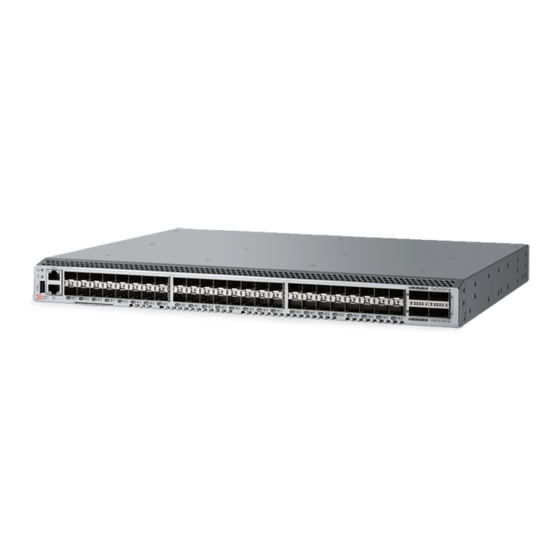
Real-time clock (RTC) with battery. License Options The Brocade G620 Switch uses a capacity-based Ports on Demand (POD) license method. An Integrated Routing (IR) license is required to enable EX_Ports on this device. Refer to the Brocade Fabric OS Software Licensing Guide for more details. - Page 11 15. SFP+ (upper) Port 10 Status LED 16. 1000/100/10Bb/s RJ-45 Ethernet Management Port 17. USB Port The following illustration shows the port-side view of the Brocade G620 (Switch Type 183) Fibre Channel switch. Figure 2: Port-Side View of G620 (Switch Type 183) 1. System Power LED 2.
-
Page 12: Nonport-Side View Of The Device
All the ports are connected to a single ASIC. Nonport-Side View of the Device The following illustrations show the nonport-side view of the Brocade G620 FC Switch. Figure 3: Nonport-Side View with AC Power Supply and Fan Assembly Units 1. #6-32 for Screw Mounting of the Ground Cable 2. -
Page 13: Device Management Options
® 53-1003990-22 Installation Guide Brocade G620 Switch Hardware Installation Guide 5. Handle 6. Airflow Label 7. Captive Screw 8. Power Supply and Fan Assembly 1 Device Management Options You can use the management functions built into the device to monitor the fabric topology, port status, physical status, and other information. -
Page 14: Preparing For Installation
® 53-1003990-22 Installation Guide Brocade G620 Switch Hardware Installation Guide Preparing for Installation This section provides information on the prerequisites for installing the device. Perform the following preliminary steps to ensure a successful installation: • Note the safety precautions to avoid harm to you or damage to the device. •... -
Page 15: Esd Precautions
® 53-1003990-22 Installation Guide Brocade G620 Switch Hardware Installation Guide CAUTION If you do not install a module or a power supply in a slot, you must keep the slot filler panel in place. If you run the chassis with an uncovered slot, the system will overheat. CAUTION Do not install the device in an environment where the operating ambient temperature might exceed 40°C (104°F). -
Page 16: Lifting And Weight-Related Precautions
All fiber-optic interfaces use Class 1 lasers. DANGER Use only optical transceivers that are qualified by Broadcom and that comply with the FDA Class 1 radiation performance requirements defined in 21 CFR Subchapter I and with IEC 60825 and EN60825. Optical products that do not comply with these standards might emit light that is hazardous to the eyes. -
Page 17: Facility Requirements
® 53-1003990-22 Installation Guide Brocade G620 Switch Hardware Installation Guide Facility Requirements Before installing the device, be sure that the following facility requirements are met. Table 6: Facility Requirements Type Requirements • Electrical An adequate supply circuit, line fusing, and wire size, as specified by the electrical rating on the switch nameplate. - Page 18 ® 53-1003990-22 Installation Guide Brocade G620 Switch Hardware Installation Guide Task Task Details or Additional Information Completed Review and verify the installation Verify that the following requirements are met. See Facility Requirements. • requirements. Power requirements • Environmental requirements • Clearance for a stand-alone or rack installation •...
-
Page 19: Shipping Carton Contents
® 53-1003990-22 Installation Guide Brocade G620 Switch Hardware Installation Guide Task Task Details or Additional Information Completed • switchname Use the command to change the default switch name. Customize the switch name and • chassisname Use the command to change the default chassis name. chassis name. -
Page 20: Mounting The Device
® 53-1003990-22 Installation Guide Brocade G620 Switch Hardware Installation Guide Mounting the Device This section provides detailed information on installing the device. You can install the device in several ways: • As a stand-alone unit on a flat surface, for example, a table top. Use the rubber feet included with the shipment to secure the device on the surface. -
Page 21: Installing The Device As A Stand-Alone Unit
® 53-1003990-22 Installation Guide Brocade G620 Switch Hardware Installation Guide Installing the Device as a Stand-alone Unit Perform the following steps to install the device as a stand-alone unit on a table: 1. Unpack the device and verify that the items listed under Shipping Carton Contents are present and undamaged. -
Page 22: Parts List
® 53-1003990-22 Installation Guide Brocade G620 Switch Hardware Installation Guide The following items are required to install the device using the Universal Four-Post Rack Kit: • No. 2 Phillips torque screwdriver • 1/4-in. slotted-blade torque screwdriver Parts List The following parts are provided with the 1U and 2U Universal Four-Post Rack Kit (XBR-R000296): Figure 5: Universal Four-Post Rack Kit Parts 1. -
Page 23: Flush-Front Mounting
® 53-1003990-22 Installation Guide Brocade G620 Switch Hardware Installation Guide 4. Rear Brackets, Long (2) 5. Bracket Extensions, Long (2) 6. Screw, 8-32 x 5/16-in. Panhead Phillips (8) 7. Screw, 8-32 x 5/16-in. Flathead Phillips (16) 8. Screw, 6-32 x 1/4-in. Panhead Phillips (8) 9. -
Page 24: Attaching The Front Brackets
® 53-1003990-22 Installation Guide Brocade G620 Switch Hardware Installation Guide Attaching the Front Brackets Perform the following steps to attach the front brackets to the device: 1. Position the right front bracket with the flat side against the right side of the device at the front of the device. 2. -
Page 25: Attaching The Extension Brackets To The Device
® 53-1003990-22 Installation Guide Brocade G620 Switch Hardware Installation Guide Attaching the Extension Brackets to the Device Perform the following steps to attach the extension brackets to the device. You can use medium and long extension brackets for this task. 1. -
Page 26: Installing The Device In The Rack
® 53-1003990-22 Installation Guide Brocade G620 Switch Hardware Installation Guide Installing the Device in the Rack Perform the following steps to install the device in the rack: 1. Position the device in the rack. Provide temporary support under the device as you secure the rail kit to the rack. 2. -
Page 27: Attaching The Rear Brackets To The Extensions
® 53-1003990-22 Installation Guide Brocade G620 Switch Hardware Installation Guide Attaching the Rear Brackets to the Extensions Perform the following steps to attach the rear brackets to the extensions. You can use short or long rear brackets for this task, depending on the depth of your rack. 1. -
Page 28: Attaching The Rear Brackets To The Rack Posts
® 53-1003990-22 Installation Guide Brocade G620 Switch Hardware Installation Guide Attaching the Rear Brackets to the Rack Posts Perform the following steps to attach the rear brackets to the rack posts: 1. Attach the right rear bracket to the right rear rack post using two 10-32 x 5/8-in. panhead screws and two retainer nuts. Use the upper and lower holes in the bracket. -
Page 29: Attaching The Front Brackets To The Rear Of The Device
® 53-1003990-22 Installation Guide Brocade G620 Switch Hardware Installation Guide NOTE The illustrations in the rack installation procedures show a 1U device, but the instructions are the same for a 2U device. The illustrations in the rack installation procedures are for reference only and may not show the actual device. -
Page 30: Attaching The Extensions To The Front Of The Device
® 53-1003990-22 Installation Guide Brocade G620 Switch Hardware Installation Guide Attaching the Extensions to the Front of the Device Perform the following steps to attach the extension brackets to the front of the device. You can use medium or long extension brackets for this task, depending on your rack depth. -
Page 31: Installing The Device In The Rack
® 53-1003990-22 Installation Guide Brocade G620 Switch Hardware Installation Guide Installing the Device in the Rack Perform the following steps to install the device in the rack: 1. Position the device in the rack, providing temporary support under the device until the rail kit is secured to the rack. 2. -
Page 32: Attaching The Rear Brackets To The Extensions At The Front Of The Device
® 53-1003990-22 Installation Guide Brocade G620 Switch Hardware Installation Guide Attaching the Rear Brackets to the Extensions at the Front of the Device Perform the following steps to attach the rear brackets to the extensions. The rack depth determines the use of short or long brackets. - Page 33 ® 53-1003990-22 Installation Guide Brocade G620 Switch Hardware Installation Guide Figure 15: Attaching the Short or Long Rear Brackets to the Extensions Rear Bracket, Short or Long Screws, 6-32 x 1/4-in. Panhead Phillips 53-1003990-22...
-
Page 34: Attaching The Rear Brackets To The Front Rack Posts
® 53-1003990-22 Installation Guide Brocade G620 Switch Hardware Installation Guide Attaching the Rear Brackets to the Front Rack Posts Perform the following steps to attach the rear brackets to the front rack posts: 1. Attach the right rear bracket to the right front rack post using two 10-32 x 5/8-in. screws and two retainer nuts. Use the upper and lower holes in the bracket. -
Page 35: Time And Items Required
® 53-1003990-22 Installation Guide Brocade G620 Switch Hardware Installation Guide • With the port side flush with the front posts • With the posts mounted to the mid-section of the device Observe the following when mounting this device: • Two people are required to install the device in a rack. One person should hold the device, while the other person screws in the front and rear brackets. -
Page 36: Flush-Front Mounting
® 53-1003990-22 Installation Guide Brocade G620 Switch Hardware Installation Guide 5. Screw, 8-32 x 5/16-in. Flathead Phillips (16) 6. Screw, 6-32 x 1/4-in. Panhead Phillips (8) 7. Screw, 10-32 x 5/8-in. Panhead Phillips (8) 8. Retainer Nut, 10-32 (8) Ensure that the items listed and illustrated in the preceding figure are included in the kit. NOTE Not all parts may be used with certain installations depending on the device type. -
Page 37: Attaching The Front Brackets To The Device
® 53-1003990-22 Installation Guide Brocade G620 Switch Hardware Installation Guide Attaching the Front Brackets to the Device Perform the following steps to attach the front brackets to the device: 1. Position the right front bracket with the flat side against the right side of the device. 2. -
Page 38: Attaching The Front Brackets To The Rack
® 53-1003990-22 Installation Guide Brocade G620 Switch Hardware Installation Guide Attaching the Front Brackets to the Rack Perform the following steps to install the device in the rack: 1. Position the device in the rack, providing temporary support under the device until the rack kit is fully secured to the rack. -
Page 39: Attaching The Rear Brackets To The Rack
® 53-1003990-22 Installation Guide Brocade G620 Switch Hardware Installation Guide Attaching the Rear Brackets to the Rack Perform the following steps to attach the rear brackets to the rack: 1. Select the proper length bracket for your post width. If your posts are 3 inches to 5 inches wide, use the brackets marked 3-5 INCH. -
Page 40: Attaching The Rear Brackets To The Device
® 53-1003990-22 Installation Guide Brocade G620 Switch Hardware Installation Guide Attaching the Rear Brackets to the Device Perform the following steps to attach the rear brackets to the device: 1. Align the right rear bracket to the right rear of the device and use four 8-32 x 5/16-in. panhead screws to attach the bracket to the device. -
Page 41: Attaching The Front Brackets To The Device
® 53-1003990-22 Installation Guide Brocade G620 Switch Hardware Installation Guide Attaching the Front Brackets to the Rack Attaching the Rear Brackets to the Rack Attaching the Rear Brackets to the Device Attaching the Front Brackets to the Device Perform the following steps to attach the front brackets to the device: 1. -
Page 42: Attaching The Front Brackets To The Rack
® 53-1003990-22 Installation Guide Brocade G620 Switch Hardware Installation Guide Attaching the Front Brackets to the Rack Perform the following steps to install the front brackets to the rack: 1. Position the device in the rack, providing temporary support under the device until the rack kit is fully secured to the rack. -
Page 43: Attaching The Rear Brackets To The Rack
® 53-1003990-22 Installation Guide Brocade G620 Switch Hardware Installation Guide Attaching the Rear Brackets to the Rack Perform the following steps to attach the rear brackets to the rack: 1. Select the proper length bracket for your post width. If your posts are 3 in. to 5 in. wide, use the brackets marked 3-5 INCH. -
Page 44: Attaching The Rear Brackets To The Device
® 53-1003990-22 Installation Guide Brocade G620 Switch Hardware Installation Guide Retainer Nuts, 10-32 Rear Brackets (Right and Left) Screws, 10-32 x 5/8-in. Panhead Phillips Attaching the Rear Brackets to the Device Perform the following steps to attach the rear brackets to the device: 1. -
Page 45: Initial Setup And Verification
PNY Attache 3.0 4 USB 32GB Flash Drive • PNY Attache 3.0 4 USB 16GB Flash Drive These drives are not orderable from Broadcom but are generically branded and can be purchased from other suppliers. Providing Power to the Device Perform the following steps to provide power to the device: 1. -
Page 46: Establishing A First-Time Serial Connection
® 53-1003990-22 Installation Guide Brocade G620 Switch Hardware Installation Guide Establishing a First-Time Serial Connection Perform the following steps to log on to the device through a serial connection: 1. Connect the device with the workstation. • For G620 (Switch Type 162), connect the serial cable to the serial port on the device and the RS-232 serial port on the workstation. - Page 47 ® 53-1003990-22 Installation Guide Brocade G620 Switch Hardware Installation Guide NOTE If the serial port on the workstation is RJ-45 instead of DB9-RS-232, remove the adapter on the end of the serial cable and insert the exposed RJ-45 connector into the RJ-45 serial port on the workstation. 2.
-
Page 48: Configuring The Ip Address
® 53-1003990-22 Installation Guide Brocade G620 Switch Hardware Installation Guide 5. Log on to the device as admin, using the default password (password ). You are prompted to change the default user name and password at the initial login. Record the new credentials and keep this information in a secure location. Fabric OS (swDir) swDir login: admin Password:... -
Page 49: Setting The Date And Time
® 53-1003990-22 Installation Guide Brocade G620 Switch Hardware Installation Guide Setting the Date and Time The date and time settings are used for event logging, error detection, and troubleshooting. However, device operation does not depend on the date and time; a device with incorrect date or time values still functions properly. You can synchronize the local time of the principal or primary fabric configuration server (FCS) device to that of an external Network Time Protocol (NTP) server. -
Page 50: Synchronizing The Local Time With An External Source
® 53-1003990-22 Installation Guide Brocade G620 Switch Hardware Installation Guide Local Time tsTimeZone Parameter (Difference from UTC) -7,0 Mountain Standard -6,0 Mountain Daylight -8,0 Pacific Standard -7,0 Pacific Daylight -9,0 Alaskan Standard -8,0 Alaskan Daylight -10,0 Hawaiian Standard Synchronizing the Local Time with an External Source Perform the following steps to synchronize the local time of the principal or primary FCS device with the time of an external NTP server: 1. -
Page 51: Establishing An Ethernet Connection
® 53-1003990-22 Installation Guide Brocade G620 Switch Hardware Installation Guide Establishing an Ethernet Connection Perform the following steps to establish an Ethernet connection to the device: 1. Remove the plug from the Ethernet port. 2. Ensure that the partner side of the link is set with Auto Negotiation turned on for proper operation. 3. - Page 52 ® 53-1003990-22 Installation Guide Brocade G620 Switch Hardware Installation Guide Command Description historyShow Displays the device history psShow Displays power supply status and information switchShow Displays switch status and information tempShow Displays temperature status and information The switchShow command provides the following information about the device and port status. EG620_192:admin>...
-
Page 53: Backing Up The Configuration
® 53-1003990-22 Installation Guide Brocade G620 Switch Hardware Installation Guide Backing Up the Configuration Back up the configuration regularly to ensure that a complete configuration is available for downloading to a replacement switch. Perform the following steps to back up the configuration: 1. -
Page 54: Installing Transceivers And Cables
All fiber-optic interfaces use Class 1 lasers. DANGER Use only optical transceivers that are qualified by Broadcom and that comply with the FDA Class 1 radiation performance requirements defined in 21 CFR Subchapter I and with IEC 60825 and EN60825. Optical products that do not comply with these standards might emit light that is hazardous to the eyes. -
Page 55: Installing An Sfp+ Transceiver
Brocade Transceiver Support Matrix and the Brocade Transceiver Modules webpage on www.broadcom.com. If you use an unqualified transceiver, the switchshow command output shows the port in a Mod_Inv state. The issue is also logged in the system error log. -
Page 56: Replacing An Sfp+ Transceiver
® 53-1003990-22 Installation Guide Brocade G620 Switch Hardware Installation Guide 2. Position a cable so that the key (the ridge on one side of the cable connector) is aligned with the slot in the transceiver. Insert the cable into the transceiver until the latching mechanism clicks. Figure 29: Installing SFP+ Cables Cable and Connector Transceiver... -
Page 57: Installing A Qsfp Transceiver
® 53-1003990-22 Installation Guide Brocade G620 Switch Hardware Installation Guide Figure 30: Installing SFP+ Transceivers Pull Tab of Transceiver in Upper Row Pull Tab of Transceiver in Lower Row 4. Position a cable so that the key (the ridge on one side of the cable connector) is aligned with the slot in the transceiver. Insert the cable into the transceiver until the latching mechanism clicks. -
Page 58: Replacing A Qsfp Transceiver
® 53-1003990-22 Installation Guide Brocade G620 Switch Hardware Installation Guide • The device supports only transceivers that are qualified for Brocade products. If you use an unqualified transceiver, the switchshow command output shows the port in a Mod_Inv state. The issue is also logged in the system error log. •... -
Page 59: Verifying The Operation Of New Transceivers
® 53-1003990-22 Installation Guide Brocade G620 Switch Hardware Installation Guide NOTE QSFP transceivers have pull tabs rather than bails. Always use the pull tab to insert or remove the QSFP transceivers, since the QSFP might be hot. 1. Remove any cables that are inserted into the transceiver. 2. -
Page 60: Monitoring The Device
Sometimes, the LEDs may flash any of the colors during boot, POST, or other diagnostic tests. This flashing is normal; it indicates a problem only if the LEDs indicate an unhealthy state after all boot processes and diagnostic tests are complete. Figure 34: Brocade G620 Port-Side LEDs (Switch Type 162) 1. System Status LED 2. System Power LED 3. -
Page 61: System Power Led
G620 Switch Hardware Installation Guide 11. FC Port 62 (QSFP 3) Status LED 12. FC Port 63 (QSFP 3) Status LED Figure 35: Brocade G620 Port-Side LEDs (Switch Type 183) 1. System Status LED 2. System Power LED 3. SFP+ (Upper) Port 0 Status LED 4. -
Page 62: Management Port Leds
® 53-1003990-22 Installation Guide Brocade G620 Switch Hardware Installation Guide Table 12: System Status LED Patterns during Normal Operation LED Color Hardware Status Recommended Action No light The system is off, or there is no power. Verify that the system is on and has completed booting. -
Page 63: Qsfp Port Status Leds
® 53-1003990-22 Installation Guide Brocade G620 Switch Hardware Installation Guide LED Color Hardware Status Recommended Action The connected device is configured in an Verify the status of the connected device. offline state. Steady green The port is online (connected to an external No action is required. -
Page 64: Interpreting Nonport-Side Leds
® 53-1003990-22 Installation Guide Brocade G620 Switch Hardware Installation Guide LED Color Hardware Status Recommended Action Steady amber Port is receiving light or signal carrier, but it No action is required. is not online yet. Slow-flashing amber (on for 2 seconds; Port is disabled because of diagnostics or Reset the port. -
Page 65: Interpreting Post Results
® 53-1003990-22 Installation Guide Brocade G620 Switch Hardware Installation Guide Interpreting POST Results Each time the switch is powered on, rebooted, or reset, it performs a power-on self-test (POST). The total boot time with the POST can take several minutes. The POST can be bypassed after subsequent reboots by using the fastboot command or entering the diagDisablePost command to persistently disable the POST. -
Page 66: Power Supply And Fan Assemblies
® 53-1003990-22 Installation Guide Brocade G620 Switch Hardware Installation Guide Power Supply and Fan Assemblies The power supply and fan assembly units can be removed and replaced without special tools. The units are identical and fit into either slot. NOTE The power supply and fan assembly units are hot-swappable if they are replaced one at a time. -
Page 67: Precautions Specific To The Power Supply And Fan Assemblies
® 53-1003990-22 Installation Guide Brocade G620 Switch Hardware Installation Guide Figure 37: DC Power Supply and Fan Assembly 1. Power-On/Off Switch 2. Power Supply and Fan Assembly Status LED 3. DC Power Cable Receptacle 4. Power Supply and Fan Assembly Handle 5. -
Page 68: Identifying The Airflow Direction
® 53-1003990-22 Installation Guide Brocade G620 Switch Hardware Installation Guide CAUTION Disassembling any part of the power supply and fan assembly voids the warranty and regulatory certifications. There are no user-serviceable parts inside the power supply and fan assembly. CAUTION Ensure that the airflow direction of the power supply unit matches that of the installed fan tray. -
Page 69: Power Supply And Fan Assembly Task Guide
® 53-1003990-22 Installation Guide Brocade G620 Switch Hardware Installation Guide • Power supply and fan assembly status LED. See Interpreting Nonport-Side LEDs to interpret the meaning of LED operation. • The Power Status icon in Web Tools. Click the icon to display status. •... -
Page 70: Time And Items Required
® 53-1003990-22 Installation Guide Brocade G620 Switch Hardware Installation Guide Time and Items Required Installing or removing and replacing a power supply and fan assembly should require less than 5 minutes to complete. The following items are required to replace a power supply and fan assembly: •... -
Page 71: Connecting A Dc Power Cord To A 250W Dc Power Supply
® 53-1003990-22 Installation Guide Brocade G620 Switch Hardware Installation Guide Connecting a DC Power Cord to a 250W DC Power Supply Perform the following steps to connect a DC power cord to a 250W DC power supply: 1. Remove the DC wiring assembly from the front of each DC power supply. Figure 38: DC Wiring Assembly Wire Tightening Screws DC Power Source Wires... -
Page 72: Removing A Power Supply And Fan Assembly
® 53-1003990-22 Installation Guide Brocade G620 Switch Hardware Installation Guide CAUTION DC return must be isolated from the chassis ground (DC-I) when connections to the power supply are made. CAUTION For a DC system, use a grounding wire of at least 16 American Wire Gauge (AWG). The grounding wire should be attached to the DC input connector;... -
Page 73: Replacing The Power Supply And Fan Assembly
® 53-1003990-22 Installation Guide Brocade G620 Switch Hardware Installation Guide Figure 40: DC Power Supply and Fan Assembly Power Supply and Fan Assembly Handle Captive Screw 2. Power off the power supply to be removed by flipping the power switch to the off position (the “O” symbol). The fans in the other power supply automatically switch to high speed to maintain adequate cooling. -
Page 74: Inserting A New Power Supply And Fan Assembly
5. Ensure that the new power supply and fan assembly have the same part number as the FRU being replaced. Figure 41: Orientation of the AC or DC Power Supply and Fan Assembly Brocade G620 Chassis AC or DC Power Supply and Fan Assembly Captive Screw 6. - Page 75 ® 53-1003990-22 Installation Guide Brocade G620 Switch Hardware Installation Guide CAUTION The power supply switch must be in the off position when you insert the power supply into the chassis. Damage to the switch can result if a live power supply is installed. NOTE The new power supply and fan assembly must have the same part number and airflow label (or lack thereof) as the power supply and fan assembly already installed.
-
Page 76: Verifying The Operation Of The Power Supply And Fan Assemblies
® 53-1003990-22 Installation Guide Brocade G620 Switch Hardware Installation Guide Figure 43: Inserting a DC Power Supply and Fan Assembly Device DC Power Supply and Fan Assembly Captive Screw 4. Gently push the power supply and fan assembly into the chassis until it is firmly seated. 5. -
Page 77: Technical Specifications
® 53-1003990-22 Installation Guide Brocade G620 Switch Hardware Installation Guide Technical Specifications The following tables highlight the features and specifications for the Brocade G620 Switch. System Specifications System Component Description Enclosure 1U, port-side back-to-front exhaust airflow, power from the back. - Page 78 Empty weight refers to the device with two power-supply and fan assemblies that are installed but no SFP+ or QSFP transceivers. Weight (Fully Model Height Width Depth Weight (Empty) Loaded) Brocade G620 4.39 cm 44.00 cm 35.56 cm 7.71 kg 8.53 kg Switch (1.73 in.) (17.32 in.) (14.00 in.)
- Page 79 40–60 VDC fused (range) Data Port Specifications (Fibre Channel) Model Name Port Numbers Media Type Description Brocade G620 0 to 47 10G, 16G, or 32G SFP+ optical Can be an F_Port, N_Port, E_Port, or EX_Port. Switch ports 48 to 63 4 x 16G (64G) or 4 x 32G (128G) Can be an F_Port, E_Port, or EX_Port.
- Page 80 ® 53-1003990-22 Installation Guide Brocade G620 Switch Hardware Installation Guide Cable Size Extended Long Port Speed (G) Short Wavelength (SWL) Long Wavelength (LWL) (Microns) Wavelength (ELWL) 62.5 21m (68 ft) 10 km (6.2 miles) 82m (269 ft) (OM2) 300m (984 ft) (OM3) 550m (1804 ft) (OM4) 62.5 33m (108 ft)
-
Page 81: Regulatory Statements
® 53-1003990-22 Installation Guide Brocade G620 Switch Hardware Installation Guide Regulatory Statements This section contains regulatory compliance statements for your device. BSMI Statement (Taiwan) Warning: This is a Class A product. In a domestic environment, this product may cause radio interference, in which case the user may be required to take adequate measures. -
Page 82: China Ccc Statement
® 53-1003990-22 Installation Guide Brocade G620 Switch Hardware Installation Guide China CCC Statement 53-1003990-22... -
Page 83: China Rohs
® 53-1003990-22 Installation Guide Brocade G620 Switch Hardware Installation Guide China ROHS FCC Warning (U.S. Only) This equipment has been tested and complies with the limits for a Class A computing device pursuant to Part 15 of the FCC rules. These limits are designed to provide reasonable protection against harmful interference when the equipment is operated in a commercial environment. -
Page 84: Taiwan Rohs Certification
® 53-1003990-22 Installation Guide Brocade G620 Switch Hardware Installation Guide Taiwan ROHS Certification 53-1003990-22... -
Page 85: Vcci Statement
® 53-1003990-22 Installation Guide Brocade G620 Switch Hardware Installation Guide VCCI Statement This is a Class A product based on the standard of the Voluntary Control Council for Interference by Information Technology Equipment (VCCI). If this equipment is used in a domestic environment, radio disturbance might arise. When such trouble occurs, the user might be required to take corrective actions. - Page 86 ® 53-1003990-22 Installation Guide Brocade G620 Switch Hardware Installation Guide Regulatory Compliance (Environmental) • 1907/2006 of the European Parliament and of the Council of 18 December 2006 concerning the Registration, Evaluation, Authorisation, and Restriction of Chemicals (EU REACH). • 2006/66/EC – Batteries and accumulators and waste batteries and accumulators (EU battery directive). •...
-
Page 87: Cautions And Danger Notices
® 53-1003990-22 Installation Guide Brocade G620 Switch Hardware Installation Guide Cautions and Danger Notices This section contains translations of safety notices for your product. Cautions A Caution statement alerts you to situations that can be potentially hazardous to you or cause damage to hardware, firmware, software, or data. - Page 88 ® 53-1003990-22 Installation Guide Brocade G620 Switch Hardware Installation Guide PRECAUCIÓN Asegúrese de que el flujo de aire en las inmediaciones de las partes anterior, laterales y posterior del instrumento no esté restringido. Electrical Cautions CAUTION Before plugging a cable into any port, be sure to discharge the voltage stored on the cable by touching the electrical contacts to ground surface.
- Page 89 ® 53-1003990-22 Installation Guide Brocade G620 Switch Hardware Installation Guide CAUTION The power supply switch must be in the off position when you insert the power supply into the chassis. Damage to the switch can result if a live power supply is installed. VORSICHT Der Schalter des Netzteils muss in der Stellung „Aus“...
-
Page 90: Danger Notices
® 53-1003990-22 Installation Guide Brocade G620 Switch Hardware Installation Guide CAUTION For a DC system, use grounding wire of at least 16 AWG. The grounding wire should be attached to the DC input connector; the other end connects to the building ground. VORSICHT Für ein Gleichstromsystem verwenden Erdungskabel von mindestens 16 AWG (1.31 mm2) (amerikanische Norm für Drahtquerschnitte). - Page 91 ® 53-1003990-22 Installation Guide Brocade G620 Switch Hardware Installation Guide DANGER Be careful not to accidently insert your fingers into the fan tray while removing it from the chassis. The fan may still be spinning at a high speed. GEFAHR Die Finger dürfen nicht versehentlich in das Ventilatorblech gesteckt werden, wenn dieses vom Gehäuse abgenommen wird.
- Page 92 ® 53-1003990-22 Installation Guide Brocade G620 Switch Hardware Installation Guide DANGER To avoid high voltage shock, do not open the device while the power is on. GEFAHR Das eingeschaltete Gerät darf nicht geöffnet werden, da andernfalls das Risiko eines Stromschlags mit Hochspannung besteht.
- Page 93 G620 Switch Hardware Installation Guide DANGER Use only optical transceivers that are qualified by Broadcom and that comply with the FDA Class 1 radiation performance requirements defined in 21 CFR Subchapter I and with IEC 60825 and EN60825. Optical products that do not comply with these standards might emit light that is hazardous to the eyes.
-
Page 94: Revision History
® 53-1003990-22 Installation Guide Brocade G620 Switch Hardware Installation Guide Revision History The revision history provides a list of the significant changes made in each version of the document. 53-1003990-22; September 23, 2022 • Added support for an alternate serial adapter. •... - Page 95 ® 53-1003990-22 Installation Guide Brocade G620 Switch Hardware Installation Guide 53-1003990-14; December 4, 2018 Editorial and stylistic changes. Added a note to Shipping Carton Contents that transceivers may be shipped in an accessory tray instead of installed in switch ports. In the Technical Specifications, under "Memory Specifications,"...
-
Page 96: Documentation Legal Notice
Broadcom reserves the right to make changes without further notice to any products or data herein to improve reliability, function, or design. Information furnished by Broadcom is believed to be accurate and reliable. However, Broadcom does not assume any liability arising out of the application or use of this information, nor the application or use of any product or circuit described herein, neither does it convey any license under its patent rights nor the rights of others.
Need help?
Do you have a question about the Brocade G620 and is the answer not in the manual?
Questions and answers