Table of Contents
Advertisement
MITSUBISHI Low-Voltage Air Circuit Breakers series
World Super AE
三菱低压空气断路器 World Super AE
三菱低圧気中遮断器 World Super AE
MODEL
AE-SW
INSTRUCTION MANUAL
使用说明书
取扱説明書
Types covered in this manual
本手册适用于以下型号产品
対象機種
AE630-SW
AE2000-SWA
AE2000-SW AE2500-SW AE3200-SW
AE4000-SWA
AE4000-SW AE5000-SW AE6300-SW
IMPORTANT NOTE:
instructions carefully, and make sure that all actual users also read them.
重要注释: 在使用 AE 断路器系列以前,请务必仔细阅读本说明书,
并确保所有用户也阅读本说明。
ご使用の前に必ずこの取扱説明書をお読みください。
この説明書は、最終ユーザまでお届けください。
AE1000-SW AE1250-SW AE1600-SW
Before using these Series AE breakers, please read these
22A
Advertisement
Table of Contents

Related Manuals for Mitsubishi Electric AE-SW Series


Summary of Contents for Mitsubishi Electric AE-SW Series
- Page 1 MITSUBISHI Low-Voltage Air Circuit Breakers series World Super AE 三菱低压空气断路器 World Super AE 三菱低圧気中遮断器 World Super AE MODEL AE-SW INSTRUCTION MANUAL 使用说明书 取扱説明書 Types covered in this manual 本手册适用于以下型号产品 対象機種 AE630-SW AE1000-SW AE1250-SW AE1600-SW AE2000-SWA AE2000-SW AE2500-SW AE3200-SW AE4000-SWA AE4000-SW AE5000-SW AE6300-SW Before using these Series AE breakers, please read these IMPORTANT NOTE: instructions carefully, and make sure that all actual users also read them.
-
Page 2: Safety Precautions
Safety precautions Before using this device, make sure to read this instruction manual thoroughly. Important safety information is included in this manual. Be sure to follow the instructions. Please make sure that the end user receives this instruction manual. ... -
Page 3: Table Of Contents
Table of contents Safety precautions ………………………………… 2 Shutter lock (SST-LOCK) ……………………… 20 External view ………………………………………… 4 Safety shutter nameplate ……………………… 20 Internal structure …………………………………… 5 Functions of electronic trip relay (ETR) parts … 21 Outline dimensions and product weight …………... -
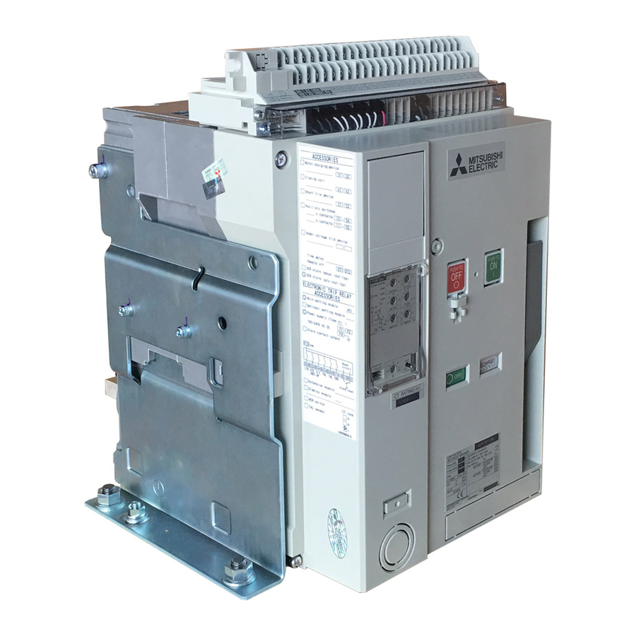
Page 4: External View
External view < Fixed type > < Drawout type > Control circuit terminal Control circuit terminal block block Lifting holes Electronic trip relay Arc-extinguishing (ETR) Cradle chamber Lifting hook (HP) OFF button ON button Charging handle Extension rail Padlock hook Charging indicator allows a padlock to be attached to the... -
Page 5: Internal Structure
Internal structure ① Control circuit terminal block ① ② Control circuit connector ② ⑨ ③ Auxiliary switch ④ Shunt trip device, closing coil, undervoltage trip device ⑤ Electronic trip relay (ETR) ③ ⑩ ④ ⑥ Cover ⑤ ⑦ Open/close mechanism ⑥... -
Page 6: Unpacking
Unpacking ① Make sure that the packing case is free from any abnormality such as being broken and/or wet. ② Check the indication on the package and the rated nameplate of the breaker, and confirm that it matches your order. Serial number is indicated on the rated nameplate and on the cradle nameplate (Fig. -
Page 7: Transportation
Transportation Do not drop the product during transportation and storage. Do not roll the product. Fig. 7-1 Fig. 7-2 Wire length 1 m or more Wire length 1 m or more Lifting hook hole Lifting hook (HP) CONNECT position Fig. 7-5 Since the conductors side is heavy, be careful not to give an impact to the product and the conductors when... -
Page 8: Installation
Installation < Drawout type > AE630-SW ~ AE3200-SW, AE2000-SWA, AE4000-SWA Installation surface flatness 1 mm or less Insert M12 bolts from above, and attach the cradle. Max. Bolt 14 mm lAppropriate tightening torque Bolt size Tightening torque (N m) 45±5 Earth terminal Fig. -
Page 9: Installation Of The Drawout Handle
Installation of the drawout handle The drawout handle can be installed either onto the right or left of the cradle as required. A drawout handle, installation bracket, installation screws, and hexagon nuts are provided with the breaker. Installation onto the left side Installation onto the right side Drawout handle Installation bracket... -
Page 10: Connection
Connection Use M12 screws (made of copper), spring washers, and small washers to connect to the conductors. Clean the contact surface and securely tighten the screws with a appropriate torque. The connecting area on main circuit terminal of the breaker is different depending on the shape of the breaker’s terminal. Refer to the outline dimensions in the catalog. - Page 11 Since fault current owing through the conductors causes large electromagnetic forces, the conductors should be secured rmly, using the values in the below table as a reference. Max. distance between xing support and breaker bus bar should be less than 200mm. Table 11-1 Electromagnetic force per 1 m of conductor (in the case of three phase short circuit) (N/m)
-
Page 12: Insert Operation
Insert operation DRAWOUT positionCONNECT position ① Pull the lock lever toward you (step 1), unhook the lock lever ② With the extension rail pulled out to the furthest position, lift the from the cradle, and then pull out the extension rail (step 2). breaker once by using a lifter or dedicated lifting hook (HP), and then lower the breaker down onto the drawout rail. - Page 13 ⑤ Press in the lock plate until it clicks onto the latch, and ⑥ Unlock, release your hands from the lock plate, and unlock. rotate the drawout handle clockwise. (Caution) (Caution) (a) If unlocking the lock plate feels difficult, slightly rotate Do not draw out during the insert operation.
-
Page 14: Drawout Operation
Drawout operation CONNECT position DRAWOUT position ① ① For AE4000-SW ~ AE6300-SW, unfasten the two fixing bolts on both sides of the cradle, and unlock. If dra- wout is performed without unlocking, the cradle and the drawout mechanism may be damaged. (Fig. - Page 15 ⑤ When the breaker is drawn out to the TEST position, ⑤ the drawout position indicator shows TEST position, and the lock plate is protruded automatically, locking the drawout handle rotation. (Caution) Do not rotate the drawout handle while the lock plate is protruded.
-
Page 16: Charging Operation
⑧ When pulling out the breaker, be sure to do so evenly ⑧ on the right and left sides. (Do not forcefully pull the right or left area only.) If it is uneven (if the breaker is coming out diagonally), it does not come out smoothly. -
Page 17: Open/Close Operation
Open/close operation < Conditions for closing operation > ON operation becomes available when the following condi- tions are met. non-OFF instructions The breaker is OFF condition. The closing spring is charged. Manual reset button The charging indicator shows “CHARGED”. The state without OFF operations. •... - Page 18 Electric open/close operation CC circuit diagram < Closing > Opening operation can be performed electrically by using a Breaker CC unit closing coil (CC). By applying the rated voltage to A1 and A2 on the control circuit terminal block, the breaker can be closed.
-
Page 19: Door Interlock (Di)
Door interlock (DI) < Procedures for releasing the door interlock > Interlocks can be manually released even if the breaker is in the ON state. For this, make a hole of ø7 or larger in the panel door. (Refer to Fig. 19-1) For the details such as installation and adjustment methods, check the instruction manual provided with the door interlock. -
Page 20: Shutter Lock (Sst-Lock)
Shutter lock (SST-LOCK) When pulling out a breaker equipped with a safety shutter (SST) from the cradle, its safety shutter can be locked in the closing position so that the live parts cannot be touched. Padlock (shackle diameter ø5 or less) A padlock (shackle diameter ø5 or less) is provided by the customer. -
Page 21: Functions Of Electronic Trip Relay (Etr) Parts
Functions of electronic trip relay (ETR) parts Option < Function description of each part > ⑤ TAL LED, contact output The ETR temperature detector becomes operable when ① ERR. LED, contact output a TAL sensor is installed. When the power supply type When any abnormality or setting failure is found in the is P3 ~ P5, a contact output is given between ETR, this provides a notification of the abnormal status. - Page 22 < Load current indicator LED > < Pre-alarm operation > The current value, which is used as a reference by the load PAL LED will blink when the current exceeds the pre-alarm current indicator LED, varies depending on the applications current setting (Ip), and will be lit after 1/2 of the long time and relay types.
-
Page 23: Characteristics Setting For The Ws Type
Characteristics setting for the WS type ⑦ Pre-alarm current: Ip ② Uninterrupted current: Iu ③ LTD time: TL ⑧ Pre-alarm time: Tp ④ STD pick-up current: Isd With MCR ⑤ STD time: Tsd t ON (ramp) t OFF ⑥ INST/MCR pick-up Max. -
Page 24: Characteristics Setting For The Wm Type
Characteristics setting for the WM type ⑦ Pre-alarm current: Ip ② LTD pick-up current: I ③ LTD time: T ⑧ Pre-alarm time: Tp ④ STD pick-up current: Isd ⑤ STD time: Tsd With MCR t ON (ramp) t OFF Max. breaking time ⑥... -
Page 25: Characteristics Setting For The Wb Type
Characteristics setting for the WB type ⑦ Pre-alarm current: Ip Max. energizing time ⑧ Pre-alarm time: Tp Max. setting value of external OCR ⑥ INST/MCR pick-up current: Ii Up to Icw Up to Icw Max. shutoff time period (0.05 s for AE4000-SW to 6300-SW) Current (%) Note) The figure shows a model with an optional... -
Page 26: Characteristics Setting For The Wf Type
Characteristics setting for the WF type [LTD curve setting "a=2"] The selectable characteristics are the 10000 following five curves. 5000 4000 Pre-alarm current : Ip -1)t = const. 3000 Ir x 0.68~1.0(0.04step)-OVER 5% -1)t = const. 2000 -1)t = const. Current setting : Ir 0.5~1.0(0.05step) x In(CT rating) (I -1)t = const. - Page 27 [LTD curve setting "a=0.02"] [LTD curve setting "a=1"] a=0.02 10000 10000 5000 5000 4000 4000 Pre-alarm current : Ip Pre-alarm current : Ip 3000 Ir x 0.68~1.0(0.04step)-OVER 5% 3000 Ir x 0.68~1.0(0.04step)-OVER 5% 2000 2000 Current setting : Ir Current setting : Ir 0.5~1.0(0.05step) x In(CT rating) 0.5~1.0(0.05step) x In(CT rating) 1.10 x Ir ...
-
Page 28: Characteristics Setting For The Optional Setting Modules
ZT40B ZT60B ZT80B ZT100B ② ER Operating time: Te Be sure to use with the ZCT specified by Mitsubishi Electric. For the ZCT installation, refer to the instruction manual provided with the ZCT. 0.15s±20% Table 28-2 Setting item Symbol Characteristic setting range... - Page 29 < Characteristics setting for the AP module > By combining this with the pre-alarm function installed as standard, the two-step pre-alarms can be constructed. For the AE630-SW low rating types, be sure to apply the control power supply. This cannot be combined with the WB type. ˜With the WS type ˜With the WM type ①...
-
Page 30: Setting Procedure For The Electronic Trip Characteristics
Setting procedure for the electronic trip characteristics < Setting procedure > Before changing the setting, turn off the breaker’s CAUTION main power supply and, the ETR’s control power Note) Move the screwdriver in the direction of the arrow. supply, and confirm that no current is flowing. ①... - Page 31 < Electronic trip relay setting example > Calculation method for the setting value is explained using the example of the AE1600-SW 1600A WS1G1 relay. In = Rated current (CT rating) Ir=0.8×In Ii=12×Ir = Rated current setting =0.8×1600A =12×1280A Iu = Uninterrupted current =1280A =15360A = LTD time...
-
Page 32: Wiring Diagram
Wiring diagram * The wiring diagram below shows a fully equipped model. See the gure below for wiring. Control power supply Wiring length 2 m or less Terminals for extension D2 D1 413 U1 Reset circuit Power supply circuit Alarm contacts Electronic trip relay (Power supply type P3 ~ P5 only) (ETR) - Page 33 Cell switch 344 342 334 332 324 322 314 312 Auxiliary switch (“b” contact) Auxiliary switch (“a” contact) Cell switch For the drawout type, the cables should have the length which allow the control circuit terminal UVT controller voltage application ˜...
-
Page 34: Technical Notes (Arc Space, Reverse Connection)
Technical notes Arc space When a short circuit current is interrupted, hot gas blows out from the exhaust port of the arc-extinguishing chamber. Provide a clearance as shown in Fig. 34. For the drawout type, ensure appropriate clearance (dimension B) to avoid pinching a finger during the drawout operation. -
Page 35: Technical Notes (Operation Environment)
[7] Any other failure found not to be the responsibility Electric or Mitsubishi Electric Sales office may be able of Mitsubishi Electric or that admitted not to be so to perform the diagnosis. In that case, for damages by the user. -
Page 36: Inspection And Maintenance
Inspection and maintenance 1. Guideline for inspection and replacement ... 36 4. Inspection ..........37 2. Appearance and structure ..... 37 5. Handling of abnormal operations ..40 3. Preparation before inspection ....37 The maintenance and inspection items and frequency differ by their operation environment. Carefully read the contents of the manual and perform thorough inspection and maintenance. - Page 37 2. Appearance and structure Refer to P.4 and P.5 of this instruction manual. 3. Preparation before inspection To perform a normal (initial or periodic) inspection, open (turn off) the upper breakers and verify that there is no cur- rent flowing. For the control circuit, perform an inspection with the power shut off whenever possible, except when inspecting its operation.
- Page 38 4.2 Periodic inspection To prevent accidents and use the breaker stably for a long period of time, we recommend an initial inspection to be per- formed after 1 month of operation followed by periodic inspections according to the operation environment. 4.2.1 Appearance of the air circuit breaker Inspection items Inspection methods...
- Page 39 4.2.5 Accessory (Please contact us for special accessories other than the ones listed below.) Inspection items Inspection methods Criteria Treatment Operates fully and smoothly in the If any abnormality is seen in the operation, 1. Closing coil (CC) Electric operation rated voltage range.
- Page 40 5. Handling of abnormal operations Treatment Types and states Faulty behaviors/estimated causes of abnormality Investigation/primary treatment Secondary treatment 1. Closing operation cannot be performed. 1. Unable to close (1)OFF locking device (CYL. CAL, Padlock) Release the OFF locking device (CYL. CAL, If closing is still unavailable after the rst is not released.
- Page 41 Treatment Types and states Faulty behaviors/estimated causes of abnormality Investigation/primary treatment Secondary treatment 1. It trips unnecessarily under normal load. Check that the load current and ETR are set abnormality found 6. Electronic trip relay (ETR) correctly. characteristics, contact your local branch (1)It trips unnecessarily.
-
Page 42: Service Network
SERVICE NETWORK According to Registration of Broadcasting and Communication Equipments belonging in “KC”, we inform of the following user guidance. Applicable models are Electronic type of ACBs, MCCBs and ELCBs. E-42... - Page 43 MITSUBISHI Low-Voltage Air Circuit Breakers World Super AE Model AE-SW 東京都千代田区丸の内 2-7-3 ( 東京ビル) 〒 100-8310 HEAD OFFICE: TOKYO BLDG., MARUNOUCHI, 2-7-3, CHIYODAKU, TOKYO 100-8310. TELEX: J24532 CABLE: MELCO TOKYO 三菱電機株式会社 福山製作所 〒 720-8647 広島県福山市緑町 1 番 8 号 TEL (084)921-3211 FAX (084)931-4714 MITSUBISHI ELECTRIC FUKUYAMA WORKS...
Need help?
Do you have a question about the AE-SW Series and is the answer not in the manual?
Questions and answers