Table of Contents
Advertisement
Quick Links
Advertisement
Chapters
Table of Contents

Related Manuals for Mitsubishi Electric V Series


Summary of Contents for Mitsubishi Electric V Series
- Page 1 MITSUBISHI Low Voltage Air Circuit Breakers World Super AE V Series 三菱低压空气断路器 World Super AE V Series MODEL 型号 AED-CV INSTRUCTION MANUAL 使用说明书 Relevant models 对象机型 AED630-CV AED1000-CV AED1250-CV AED1600-CV This is our management code. 是三菱电机管理代码。...
- Page 2 • Failure caused by reasons unpredictable based on scientific technology standards at the time of shipment from Mitsubishi Electric. • Any other failure found not to be the responsibility of Mitsubishi Electric or that admitted not to be so by the user.
- Page 3 If the products listed in this catalogue are used for the above mentioned special uses, Mitsubishi Electric does not take any responsibility for the quality, performance, and safety of the product, which includes, but is not limited to, default liability, defect liability, quality assurance liability, tort liability, and product liability.
- Page 4 DANGER • Do not use the product under the conditions with over-rated current. Otherwise, ground-fault or short circuit fault could occur due to dielectric breakdown, or explosion could occur due to a short circuit protection failure. • Do not touch terminal area. There is a risk of electrical shock. CAUTION •...
-
Page 5: Table Of Contents
Contents 1. Appearance ..........................6 2. Outline dimensions ........................7 3. Package ............................7 4. Storage ............................8 5. Required tool ..........................8 6. Unpacking ............................. 9 6.1 Fixed type ........................10 6.2 Drawout type ........................10 6.3 CONNECT → DISCONNECT position ................11 6.4 DISCONNECT →... -
Page 6: Appearance
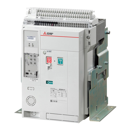
1. Appearance ■ Fixed type Electronic trip relay Control circuit terminal block OFF button ON button Manual reset button Padlock hook ON/OFF indicator Mounting plate ■ Drawout type Control circuit terminal block Lifting hole Cradle Lifting hole Junction Hole to store Extension rail the drawout handle Drawout handle... -
Page 7: Outline Dimensions
2. Outline dimensions ■ Fixed type ■ Drawout type (mm) Type AED630-CV to AED1600-CV 3-pole 410 × 340 × 294 Fixed type 4-pole 410 × 425 × 294 Dimensions (H × W × D) 3-pole 430 × 300 × 375 Drawout type 430 ×... -
Page 8: Storage
4. Storage Before using the circuit breaker stored six (6) years or longer, oil the oiling points described in Inspection and Maintenance. For details, please contact our service network. +60℃ -20℃ Average temperature for 24 hours, Control humidity to prevent condensation. No direct sunlight. -
Page 9: Unpacking
6. Unpacking 1. Make sure that the packing case is free from Not attached any abnormality such as breaking and/or wetting. 2. Check the rated nameplate to make sure it is the ordered product. The following content is described on the rated nameplate. (Note) Rated nameplate... -
Page 10: Fixed Type
6.1 Fixed type Remove the four fixing bolts as shown. (Note) Lifting hooks are bundled. Regarding how to use the hooks, refer to section 7. 6.2 Drawout type 6.2.1 Drawout device position ■ DISCONNECT position ■ TEST position ■ CONNECT position Projection Projection Projection... -
Page 11: Connect → Disconnect Position
6.2.2 Operating method of the drawout type Take out the drawout handle from the circuit breaker. Turn the drawout handle to change the drawout position from CONNECT to DISCONNECT. Regarding how to operate the drawout handle, refer to section 6.3. 6.3 CONNECT →... - Page 12 3. After pushing the lock plate, insert the drawout handle and rotate the handle in the direction of the arrow as shown. (Note) Do not rotate the drawout handle in the opposite direction. The drawout position indicator may not function correctly. In this case, pull the unit out to the circuit disconnecting position and insert it to the circuit connecting position.
- Page 13 6.1 After drawing out the circuit breaker to the DISCONNECT position, remove the dra- wout handle. 6.2 Draw out the left and right side of the circuit breaker simultaneously from the cradle. CAUTION Be careful not to injure your hands and fingers by the items in the panel when drawing out the circuit breaker.
-
Page 14: Disconnect → Connect Position
6.4 DISCONNECT → CONNECT position 1. Release the lock levers, and pull the extension Extension rails Lock lever rails forward. CAUTION Pull Pull Falling Pull out the extension rails while pulling the lock lever. If the circuit breaker main body is put on the rails with the cradle unsecured, the center of gravity shifts to the front. - Page 15 4. Keeping the OFF button pushed, insert the drawout handle. OFF button OFF button Make sure that the drawout position indicator shows DISCONNECT. (Prohibition) Do not insert the drawout handle forcibly unless the OFF button is pushed. There is a possibility of damaging. Insert DISCONNECT position DISCONNECT...
- Page 16 7. When the circuit breaker is inserted to the test position, the drawout position indicator shows TEST position and the lock plate automatically protrudes to lock the drawout Automatic handle. TEST position DISCONNECT TEST CONNECT 8. Then, push the lock plate and turn the handle Lock position clockwise.
-
Page 17: Handling
7. Handling Never drop the circuit breaker when handling. Never roll the circuit breaker when handling. Weight (kg) CAUTION CAUTION Type AED630-CV to AED1600-CV 3-pole Fixed type 4-pole 3-pole Drawout type 4-pole (Note) a. The values in the table are typical values, not guaranteed values. -
Page 18: Installation
8. Installation Install the circuit breakers as the following procedures. ■ Fixed type ■ Drawout type Tightening torque: Tightening torque: 45±5 N・m 45±5 N・m Grounding Grounding terminal (Note) terminal (Note) Tightening torque: Tightening torque: 12±1.2 N・m 12±1.2 N・m CAUTION CAUTION Do not mount the bolts reversely. - Page 19 CAUTION When installing the circuit breaker, observe the following precautions. Do not give the circuit breaker Tolerance of the mounting surface Use the circuit breaker in a panel. Keep off dust and dirt. shock or vibration. Cover the circuit breaker with a sheet or Doing so can cause the circuit breaker others during installation.
-
Page 20: Universal Terminal
8.1 Universal terminal ■ Fixed type ■ Drawout type Universal Universal terminal terminal M8×15 M8×15 Torque Torque 16.5±1.5 N・m 16.5±1.5 N・m Horizontal Horizontal Universal Universal terminal terminal M8×15 M8×15 Torque Torque 16.5±1.5 N・m 16.5±1.5 N・m (Note) Before mounting the Vertical Vertical terminals, clean the mounting surface and... -
Page 21: Precautions For Connecting
8.2 Precautions for connecting Use M12 bolts, plain washers, and spring washers to connect the conductor. Clean the surface of conductor to be connected to the (silver plating) terminal of circuit breaker and securely tighten the bolts with a correct torque (M12: 45±5 N·m). -
Page 22: Check Of The N-Pole (4-Pole)
8.3 Check of the N-pole (4-Pole) The position of N-pole is selectable. Check the label on the rear side of the circuit breaker before connecting. ■ Fixed type ■ Drawout type N-pole: Left (Option) N-pole: Left (Option) N-pole: Left (Option) N-pole: Left (Option)... -
Page 23: Attachment Of The Interphase Barrier
9. Attachment of the Interphase barrier Insert the Interphase barriers in the slot on the circuit breaker. ■ Fixed type ■ Drawout type CAUTION After inserting, pull the interphase barriers to check that the barriers are correctly installed in the slot. 10. -
Page 24: Direct Switching Operation
Circuit breaker (solenoid) control rating Applicable Current Criterion for power Rated voltage (V) Applied voltage (V) Operating time (s) voltage range (V) (Peak value) (A) requirement 110-125 93.5-137.5 1000 VA (50/60 Hz) 220-250 187-275 ≤ 0.3 110-125 93.5-137.5 1000 W 220-250 187-275 (Note) In consideration of the voltage drop, set the power supply capacity for the solenoid not to be less than the operating voltage. -
Page 25: Remote Opening/Closing Operation
10.3 Remote opening/closing operation 10.3.1 Closing When the voltage for the ON operation is applied Standard controller diagram to A1 and A2 of the control circuit terminal block and the ON switches S1 and S2 on the outside of the circuit breaker are turned Solenoid Solenoid coil... -
Page 26: Ocr Alarm (Al) [Mre: Manual Reset Type]
11. OCR alarm (AL) [MRE: Manual reset type] AL is standard equipment on the circuit breaker with ETR. When the circuit breaker trips with the LTD, STD, INST, or GF pickup current, the manual reset button protrudes and AL is output continuously. In this case, to reset the circuit breaker, press the manual reset button on the front of the circuit breaker until the button clicks. -
Page 27: Cylinder Lock (Cyl)
12. Cylinder lock (CYL) Option 12.1 Locking procedures 1. Press the OFF button to turn off the circuit breaker. OFF button OFF button 2. Hold down the OFF button and turn the key to the locking side. Then, the key can be removed, and the circuit breaker will be locked in the off state. -
Page 28: Safety Shutter (Sst)
13. Safety shutter (SST) Option SST can have the upper shutter and the lower shutter kept open independently. Operational rod Operational rod 1. Push the operational rod of the shutter to be held until the shutter opens, and turn the rod counterclockwise. -
Page 29: Safety Shutter Lock (Sst-Lock)
14. Safety shutter lock (SST-Lock) Option The safety shutter can be locked at the closing position so that the live parts are not touched. Prepare a padlock by yourself. Shutter lock 1. Mount the shutter lock to the safety shutter. Padlock ( φ... -
Page 30: Cell Switch (Cl)
15. Cell switch (CL) Option 15.1 How to check the specifi cations The terminal screws on the cell switch are arranged corresponding to the terminal numbers on the rated nameplate. Nameplate 1 Drawout type Cell switch Terminal number Terminal screw Nameplate 2 * In case of CL: 2C1T1D 15.2 How to connect terminals... -
Page 31: Electronic Trip Relay (Etr) Section
16. Electronic trip relay (ETR) section 1. ERR. LED, Contact alarm output RUN LED When any abnormality or setting failure is found in ETR, the LED alerts the operators TYPE S1 INST to the abnormal status. When the power OVER ERR. -
Page 32: Load Current Led
16.1 Load current LED The current value which is used as the reference of the load current indication LED varies depending on the characteristics setting. When the “OVER” LED is lighting, the current value Usage ETR type Base current LED indication is over LTD pick-up current. - Page 33 Self-holding/Automatic reset setting of 5 contacts 1. LTD 2. STD/INST 3. GF 4. PAL 5. ERR. Self-holding Self-holding Refer to lower table Automatic reset Automatic reset ETR dial set TRIP side Self-holding ALARM side Automatic reset Self-holding: The output is maintained until it resets. Automatic reset: The output will be reset if it backs to normal condition.
-
Page 34: Characteristics Setting Of Etr
17. Characteristics setting of ETR 17.1 Setting of over-current tripping characteristics Operating characteristic curve (for general purpose: Type S1) 5000 4000 3000 2000 Pre-alarm current: Ip Iu × 0.68-1.0 (step 0.04) - OVER ±10% 1000 Uninterrupted current: Iu (min) Ir × 0.8-1.0 (step 0.02) LTD pick-up 1.05 ×... -
Page 35: Setting Of Ground Fault Protection Characteristics
17.2 Setting of ground fault protection characteristics Option Ground fault protection characteristic curve (xln) Ground fault pick-up current: lg In × 0.1-1.0 ±20% (step 0.1) Freq. TRIP ALARM 50Hz 60Hz TEST RESET 1.15 TEST (OVER) (xlu) L/S LOCK (Note) Ground fault time: Tg (Note) When the 3-pole circuit breaker is used 0.1-0.15-0.3-0.5-0.8-1.5-3.0 (s) ±20% on a 3-phase 4-wire system, the N-pole... -
Page 36: Setting Procedure
17.3 Setting procedure 1. Prepare a small flat tipped screwdriver. Press the screwdriver in the direction of the arrow to open the ETR cover. Sealing hole Side view of the flat tip ETR cover Operating hole for resetting 2. Insert the flat tipped screwdriver into the opening of the ETR cover. -
Page 37: Precautions When Checking Characteristics Using The Field Test Device
17.4 Precautions when checking characteristics using the fi eld test device CAUTION (Note) For the operating procedures of field test devices Y-2005 Before performing the test, make sure that no and Y-2000 (discontinued model), refer to the instruction power is supplied to the main circuit of the circuit manual included with the field test device. -
Page 38: Procedures For Operating Display (Lcd)
18. Procedures for operating Display (LCD) Option A protective sheet has been affixed on the Display (LCD) to prevent scratches. Remove the sheet before starting the operation. When removing the protective sheet, static electricity may be generated to light the LCD. However, it will go off in a short time by self-discharge. -
Page 39: Screen Display And Lcd Setting
18.4 Screen display and LCD setting 18.4.1 Menu selection and screen display Selecting the menu on the MAIN screen opens the screen for each item. • METER : Measured value display • TRIP : Trip information display • SETTING : Liquid crystal display (LCD) setting The currently displayed screen item is shown in white letter. -
Page 40: Display Of Measured Values
18.5 Display of measured values 18.5.1 Measurement items On the METER menu, measured values of load current (CURRENT) and harmonic current (HARMONIC) can be displayed. Fixing with the Display of load current Refer to 18.5.2 Display of harmonic current value Refer to 18.5.3 Display of distortion rate and content rate... - Page 41 18.5.3 Harmonic current ■ Display items (Note) To measure the accurate value, set the • Present value of the fundamental wave in each phase frequency selector switch according to the • Present value of harmonics (3rd, 5th, 7th, and 9th circuit frequency to be used as described harmonic) of each phase in page 31.
-
Page 42: Trip Information
18.6 Trip information When tripping has occurred, the trip information screen will appear automatically, and the back light will change from white to red. The trip information screen will remain displayed until tripping is reset. The trip information means the history of the cause of the last fault. ■... -
Page 43: Troubleshooting Of Etr
19. Troubleshooting of ETR If you have encountered a trouble during operation, check the following items. 1. Current is displayed as 0 A when you perform a test with the field test device. While the test signal and voltage are input by the field test device, the LCD indicates the current value as 0 A according to the specifications. -
Page 44: Wiring Diagram
20. Wiring diagram Solenoid Controller Circuit breaker ON button STD/INST Common ERR. RESET E-44... -
Page 45: Technical Note
≤ 0.05 ppm, NH ≤ 0.25 ppm) d. Installation condition When installing the AE V Series air circuit breaker, refer to “22. Inspection and Maintenance” (page 46) in the catalogue and instruction manual. e. Replacement yardstick Approx. 15 years. It is dependent on the environment. Please refer to “22. Inspection and Maintenance”... -
Page 46: Inspection And Maintenance
(Note 1) Operating cycles shall be regarded as being with rated current, even if the current is much less than the maximum rated current of the circuit breaker. (Note 2) When an after-sale service person approved by Mitsubishi Electric inspects and maintains the products according to the period of use and usage environment... -
Page 47: Preparation Before Inspection
22.2 Preparation before Inspection CAUTION Before inspecting the circuit breaker, open (turn OFF) the upper circuit breaker and check that the power is not supplied. If the circuit breaker is ON, open (turn OFF) the circuit breaker and perform the drawout operation. CAUTION ... -
Page 48: Inspection Details
22.3 Inspection Details CAUTION If you find any failure during the inspection, take corrective action immediately. If the product with any failure is used, the product may be damaged, leading to secondary accidents. 22.3.1 Initial Inspection 22.3.1-1 Inspection prior to applying current Perform the following inspections after installing the circuit breaker and before applying the current. - Page 49 Perform the user inspection described in this section once about a month after starting use. After that, perform the inspection depending on the usage environment. For the periodic inspection (performed by an after-sale service person) in section 22.1, contact the sales representative or Mitsubishi Electric sales office. 22.3.2-1 External appearance of the circuit breaker...
- Page 50 22.3.2-5 Accessory devices (General accessory devices) Inspection item Inspection method Criteria Treatment 1. Shunt trip device (SHT) The circuit breaker is ON and The circuit breaker must be Please contact Mitsubishi the specified voltage is applied changed from ON to OFF. Electric if there is any breakage to the terminals C1 and C2 .
-
Page 51: Fault Diagnosis
Investigation/Primary treatment Secondary treatment 1. The circuit breaker 1. The closing operation cannot be Release the OFF-lock device. Please contact Mitsubishi Electric is not closed. performed. (CYL, CAL, Padlock) if closing cannot be performed 1.1 The OFF-lock device (CYL,... - Page 52 Secondary treatment 4.3 Abnormalities 1. The trip indicator LED or alarm Check that the control power is Please contact Mitsubishi Electric. supplied at terminals P1 and of Indication contact output does not work. P2 , and the RUN LED lights up.
-
Page 53: Service Network
Vte. Agua Santa 4211 Casilla 30-D (P.O. Box) Vina del Mar, Chile +56-32-2-320-600 Mitsubishi Electric Automation (China) Ltd. Mitsubishi Electric Automation Building, No.1386 Hongqiao Road, Shanghai, 200336 +86-21-2322-3030 Mitsubishi Electric Automation (China) Ltd. BeiJing Branch 5/F, ONE INDIGO, 20 Jiuxianqiao Road Chaoyang District, Beijing, China 100016 +86-10-6518-8830 Mitsubishi Electric Automation (China) Ltd. - Page 54 World Super AE V Series AED-CV...
- Page 55 • • • • • • •...
- Page 56 • • • • • • • •...
- Page 57 • • • • • • • • 50/60Hz •...
- Page 58 ............................6 ............................7 · ..........................7 · ..........................8 ..........................8 ............................... 9 ..........................10 ..........................10 6.3 CONNECT DISCONNECT .............. 11 6.4 DISCONNECT CONNECT .............. 14 ............................. 17 ............................. 18 .......................... 20 ........................21 8.3 N 4-Pole ................... 22 ..........................
- Page 59 ■ ■...
- Page 60 2. 外形尺寸 ■ 固定型 ■ 抽出型 3 极 4 极 3 极 4 极 深 宽 深 (mm) 型号 AED630-CV~AED1600-CV 3 极 410 × 340 × 294 固定型 4 极 410 × 425 × 294 尺寸 (高 × 宽 × 深) 3 极...
- Page 61 4. 储存·安放须知 经过储存后的使用, 如果储存期间已超过6年, 请根据检查/维护手册的 “润滑油润滑要领书” 对本体润滑后再进行 使用。 请从销售公司获取润滑油润滑要领书。 +60℃ -20℃ 避免潮湿空气,以防止结露。 24 小时的平均温度不得超过 35℃。 相对湿度:最大为 85%。 禁止阳光直射。 S(硫化氢) < 0.01ppm (二氧化硫) < 0.05ppm (氨) < 0.25ppm 请勿在拆包的状态下进行储存。 请在包装的状态下进行储存。 请在 OFF 状态下进行储存。 5. 必要使用工具 外六角扳手 一字螺丝刀 十字螺丝刀 内六角扳手 • 断路器的拆包及安装 •...
- Page 62 6. 拆包 1. 请确认包装箱无异常情况,例如损坏、水湿 自备 等。 2. 请通过断路器本体的铭牌确认与您的订单要 求相符。 (注) 铭牌 固定型包装中附带提升吊钩 (HP) 。 • 断路器 编号 说明 LOW VOLTAGE AED1600-CV A I R CIRCUIT BREAKER 断路器种类 1600 IEC 60947-2 EN 60947-2 GB/T 14048.2 本体型号 Ir MAX. 40℃ Ics=100%Icu POLE 额定电流...
- Page 63 6.2.1 ■ DISCONNECT ■ TEST ■ CONNECT DISCONNECT DISCONNECT DISCONNECT TEST TEST TEST CONNECT CONNECT CONNECT DISCONNECT TEST DISCONNECT C-10...
-
Page 64: Connect Disconnect
6.2.2 CONNECT DISCONNECT 6.3 CONNECT DISCONNECT DISCONNECT TEST CONNECT C-11... - Page 65 TEST CONNECT TEST DISCONNECT TEST CONNECT DISCONNECT DISCONNECT DISCONNECT TEST CONNECT C-12...
- Page 66 DISCONNECT C-13...
-
Page 67: Disconnect Connect
6.4 DISCONNECT CONNECT C-14... - Page 68 DISCONNECT C-15...
- Page 69 TEST TEST DISCONNECT TEST CONNECT CONNECT CONNECT DISCONNECT TEST CONNECT CONNECT TEST C-16...
- Page 70 重量 AED630-CV to AED1600-CV ■ ■ CONNECT DISCONNECT TEST CONNECT C-17...
- Page 71 ■ ■ 45±5N・m 45±5N・m 接地端子(注) 接地端子(注) 12±1.2N・m 12±1.2N・m 禁止反向安装螺栓 禁止反向安装螺栓 P14 P16 C-18...
- Page 72 C-19...
- Page 73 ■ ■ M8×15 M8×15 16.5±1.5N・m 16.5±1.5N・m M8×15 M8×15 16.5±1.5N・m 16.5±1.5N・m C-20...
- Page 74 M12 45 5N·m N·m 45 5 25mm 45±5N·m 断路器端子 200mm AED630-CV AED1600-CV 30 (0.2) 7,700 42 (0.2) 15,100 50 (0.2) 21,400 40 C GB/T 14048.1 IEC 60947-1 1000 1250 1600 IEC60947-1 C-21...
-
Page 75: N 4-Pole
8.3 N 4-Pole ■ ■ ■ M3.5×10 1.0±0.2N・m M3.5 1.25mm 2.0mm N2-M3 RAP2-3.5 FN2-M3 RBP2-3.5 N2-YS3A J.S.T. Mfg. Co.,Ltd. 7.2mm C-22... - Page 76 ■ ■ 10.1 OFF 指令 AC110-125V AC220-250V DC110-125V DC220-250V • • • • • OFF C-23...
- Page 77 110-125 93.5 137.5 1000VA 50/60Hz 220-250 187 275 110-125 93.5 137.5 1000W 220-250 187 275 10.2 10.2.1 ON/OFF castell CONNECT TEST 10.2.2 ON/OFF C-24...
- Page 78 10.3 10.3.1 U V T 1min/ 10.3.2 DT1 DT2 DT1 DT2 SHT UVT C-25...
-
Page 79: Al Mre
11. OCR LTD STD INST GF (50/60Hz) 16.3 C-26... -
Page 80: Cyl
任 12.1 12.2 C-27... -
Page 81: Sst
任 按下 按下 按下 按下 BUSBARS CABLES C-28... -
Page 82: Sst-Lock
SST-Lock 任 (φ5或者φ6) C-29... - Page 83 任 15.1 * CL:2C1T1D 15.2 CL-C CONNECT CL-T TEST CL-D DISCONNECT 20mm 0.98±0.2N・m C-30...
-
Page 84: Etr
16. 智能脱扣器 (ETR) 各部位功能 1. ERR. LED与触点输出 RUN LED 如果在ETR中发现了异常情况或设置故障, 则 提醒异常情况。 当电源类型为P3/P4时, 在控 TYPE S1 制电路端子台上的 513 与 574 之间提供触 INST OVER 点输出功能。 ERR. LED • ETR功能异常 (微处理器、 H/W) ERR. (×In) i(×Ir) • 与ETR相关的内部接线异常 Iu ×2 2. RUN LED 脱扣指示器... -
Page 85: Led
16.1 OVER OVER 16.2 PAL LED LT1/2 PAL LED DP ETR PAL LED 1/2 T 16.3 AC100-240 (50/60 Hz)/ AC85-264 DC100-125 DC85-138 DC24-60 DC18-72 cosφ = 0.4 cosφ = 1.0 L/R = 0.7 (50/60 Hz) 0.05 C-32... - Page 86 1. LTD 2. STD/INST 3. GF 4. PAL 5. ERR. P3 P4 C-33...
-
Page 87: Etr
17.1 5000 4000 3000 2000 0.68〜1.0 0.04 OVER 10 1000 (min) 0.8〜1.0 0.02 1.05 1.25 12-25-50-100-150 /2 20 1.5-2-2.5-3-4-5-6-7-8-9-10 15 TYPE S1 INST OVER ERR. (×In) i(×Ir) 0.06-0.1-0.2-0.3-0.4-0.5 Iu ×2 (×Ir) L(s) INST (×Ir) (xln) 2-4-6-8-10-12-16 15 Freq. TRIP ALARM 50Hz 60Hz 1000... - Page 88 17.2 任 (xln) 0.1〜1.0±20% Freq. TRIP ALARM 50Hz 60Hz TEST RESET 1.15 TEST (OVER) (xlu) L/S LOCK 0.1-0.15-0.3-0.5-0.8-1.5-3.0 ( s) ±20% N CT NCT Ig 0.1 100125 150 200 1000 Tg = 0.1 0.1s 50% Tg = 0.15 0.15s 30% 0.1-0.2-0.3-0.4-0.5-0.6-0.7-0.8-0.9-1.0 ×...
- Page 89 17.3 TYPE S1 INST OVER ERR. (×In) i(×Ir) 0.02N m Iu ×2 (×Ir) L(s) INST (×Ir) 0.02N・m或以下 (xln) TRIP ALARM TEST RESET 1.15 TEST (OVER) (xlu) L/S LOCK DP ETR 3 N或以下 (xln) Freq. TRIP ALARM 50Hz 60Hz 50Hz/60Hz C-36...
- Page 90 17.4 Y-2005 Y-2000 Y-2005 Y-2000 Y-2005 S1 S3 ALARM TRIP (xln) Freq. TRIP ALARM 50Hz 60Hz INST TYPE S1 INST OVER Ir=0.5 Ig=1.0 ERR. (×In) i(×Ir) Iu ×2 Ir=0.5 Ig=1.0 (×Ir) L(s) INST (×Ir) Ir :0.5 In Tg=0.3s (xln) :1.0 In 0.4s Tg :0.3s TRIP Freq.
- Page 91 任 18.1 0 200% In ***** A In = 630A 1600A ー ***** A In = 630A 1600A 0 100% In ***.* % ***** A 0 19999A 0 2000% In ー ***.* kA 20000A INST 0 200% In ***** A 0 24:00 h: m 18.2...
- Page 92 18.4 18.4.1 MAIN • METER • TRIP • SETTING : 18.5.1 18.6 18.4.2 18.4.2 SETTING CONTRAST -2/-1/0/+1/+2 SETTING LCD-BL AUTO OFF Auto OFF AUTO OFF C-39...
- Page 93 18.5 18.5.1 METER CURRENT HARMONIC 18.5.2 18.5.3 18.5.4 18.5.2 ■ • • • C-40...
- Page 94 18.5.3 ■ • • 3 5 7 9 • • • • • • • 3、 5、 7、 9 18.5.4 ■ • • • • • • • • C-41...
- Page 95 18.6 TRIP ■ • P3/P4 • • C-42...
- Page 96 • • • ---- ---- C-43...
- Page 97 STD/INST ERR. RESET C-44...
- Page 98 21.1 AED630-CV AED1600-CV AC500V ( 1 300mm ( 2 21.2 21.3 AE V 2000m 6600 S 0.01ppm SO 0.05ppm NH 0.25ppm AE V 2000m C-45...
- Page 99 22.3 22.1 22.1.1 22.1.2 AED630-CV AED1000-CV 6,000 4,000 10,000 每500个周期 每2,000个周期 AED1250-CV AED1600-CV C-46...
- Page 100 22.2 • • C-47...
- Page 101 22.3 检查详情 注意 检查时发现异常的情况下,请立即采取相应措施。如果在异常状态下使用,可能会因断路器的故障而导致连带事故的发生。 22.3.1 初始检查 22.3.1-1 在加电前进行检查。 在安装断路器以后、 加电以前,进行如下检査。 检查项目 原则 1. 电线与短棒是否稳固地连接到了外部线路连接用的主端子上? 必须按照指定拧紧扭矩旋紧。 ( M12螺丝: 45±5N・m) 2. 是否有导电性异物,如螺丝、 钉子、 面板上掉下的处理器芯片等以及进行耐压测 必须完全清除。 试所使用的连接导线遗留在端子附近? 3. 是否前保护罩、 底座等出现裂缝或者受损? 决不能有裂缝或者受损迹象。 4. 断路器是否进水或者是否有凝露? 不能进水或者有凝露。 (注1) 在进行耐压测试时,需要按照22.3.1-2中的标准进行。 (注2) 在使用500V兆欧表测量绝缘电阻的时候,需要按照22.3.1-2中的标准进行。 22.3.1-2 绝缘电阻试验与耐压试验的位置 绝缘电阻测试 (MΩ) ( 注1) 耐压测试...
- Page 102 22.3.2 22.1 22.3.2-1 45 5N m M3.5 1.0 0.2N m 22.3.2-2 DC500V AED- 22.1. 22.3.2-3 5.4 0.8N m 22.3.2-4 Y-2005 Y-2005 C-49...
- Page 103 22.3.2-5 LAXa LAXb DISCONNECT CONNECT 22.3.3 22.3.2 LTD STD 22.1.2 STD INST 22.3.2 22.3.2 2000V INST 22.3.3 C-50...
- Page 104 22.4 CYL CAL 1.1 OFF CYL CAL CONNECT DISCONNECT TEST 10.3.2 ー ー 3. ON ー 4. AL AL RESET ー ー ー 2. SHT ー ー 3. OFF ー ー ー STD/INST 3. ERR. LED ー 4. RUN LED C-51...
- Page 105 TEST ー CONNECT TEST ー CONNECT ー ー ー ー ー TEST ー CONNECT ー 9. UVT C-52...
- Page 106 ■ 1386 200336 021 2322-3030 021 2322-3000 5 504-506 100016 010 6518-8830 010 6518-8030 C 2302 110003 024 2259-8830 024 2259-8030 116600 0411 8765-5951 0411 8765-5952 2003 300061 022 2813-1015 022 2813-1017 18 S1 210002 025 8445-3228 025 8445-3808 ˙ 24 DE 710065 029 8730-5236...
- Page 107 Mitsubishi Electric Low Voltage Equipment(Xiamen)Co., Ltd. MITSUBISHI Low Voltage Air Circuit Breakers World Super AE V Series 三菱低压空气断路器 World Super AE V Series MODEL 型号 AED-CV 東京都千代田区丸の内2-7-3(東京ビル)〒100-8310 HEAD OFFICE: TOKYO BLDG., MARUNOUCHI, 2-7-3, CHIYODAKU, TOKYO 100-8310. TELEX: J24532 CABLE: MELCO TOKYO 福山製作所...
Need help?
Do you have a question about the V Series and is the answer not in the manual?
Questions and answers