Advertisement
Advertisement
Table of Contents

Related Manuals for Mitsubishi Electric NF50


Summary of Contents for Mitsubishi Electric NF50
- Page 1 CIRCUIT BREAKER MODEL NF50 AND NF100 QUICK START MANUAL Mitsubishi Electric Automation, Inc.
-
Page 2: Table Of Contents
NF50 AND NF100 CIRCUIT BREAKER QUICK START MANUAL 1. SAFETY PRECAUTIONS ..........3 1.1 STORAGE AND TRANSPORTATION ........3 1.2 STANDARD WORKING CONDITIONS ....... 3 1.3 MOUNTING AND CONNECTIONS ........3 1.4 PRECAUTIONS FOR CONNECTIONS ....... 4 1.5 MAINTENANCE AND INSPECTIONS......... 4 2. -
Page 3: Safety Precautions
NF50 AND NF100 CIRCUIT BREAKER QUICK START MANUAL 1. SAFETY PRECAUTIONS the neutral wire cannot be detected. • When there are two terminal screws for the neutral pole, tighten the Carefully read the safety precautions prior to use the circuit breaker screws alternately. -
Page 4: Precautions For Connections
NF50 AND NF100 CIRCUIT BREAKER QUICK START MANUAL • Do Not Block Ventilation Ports Do not block the ventilation ports. Electromagnetic force applied per 1m conductor (During 3-phase short-circuit) The breaker performance could drop. • Avoid Direct Sunlight Make sure that the breaker is not subject to... - Page 5 NF50 AND NF100 CIRCUIT BREAKER QUICK START MANUAL n PRECAUTIONS Inspection Model Criterion Remarks • Withstand Voltage Test A guide for the test is given on the items Are any of the following. Do not perform a withstand voltage test exceeding these conductors No conductor must be loose.
-
Page 6: Specifications
NF50 AND NF100 CIRCUIT BREAKER QUICK START MANUAL • If the intensity of the fault current cannot be estimated, measure DANGER Continuing user of a circuit breaker which has reached its the insulation resistance. If the specified value (5MΩ) has not service life can result in the following problems. -
Page 7: Model Number Selection
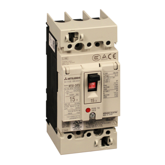
NF50 AND NF100 CIRCUIT BREAKER QUICK START MANUAL 3. MODEL NUMBER SELECTION NF100-HRU Trip Amperage Rated Current (A) See Table Above Symbol Number of Poles 2 Poles 3 Poles Symbol Molded Case Circuit Breakers 50-SVFU 100-HRU 4. DIMENSIONS NF50-SVFU 5. AMBIENT TEMPERATURE NF50-SVFU M5×0.8 screw... -
Page 8: Internal Connection Diagram
NF50 AND NF100 CIRCUIT BREAKER QUICK START MANUAL 6. INTERNAL CONNECTION DIAGRAM 7. OPERATING CHARACTERISTIC CURVES NF50-SVFU NF50-SVFU Test button Test button (UL 489) Power Power 30min Load side Load side 20min source side source side 14min 10min Max. (3A~30A)... - Page 9 MITSUBISHI ELECTRIC AUTOMATION, INC. 500 Corporate Woods Parkway, Vernon Hills, IL 60061 Ph 847.478.2100 • Fx 847.478.2253 us.MitsubishiElectric.com/fa/en/support January, 2016 • ©2016, Mitsubishi Electric Automation, Inc. • Specifications subject to change without notice. • All rights reserved AZ-Y-0720-1203 Mitsubishi Electric Automation, Inc.
Need help?
Do you have a question about the NF50 and is the answer not in the manual?
Questions and answers