Table of Contents
Advertisement
Quick Links
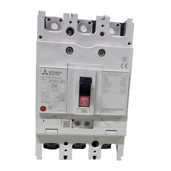
MDU Breaker
Programming Manual
MELSEC-Q Series Sequencer CC-Link Communication Version
Applicable models
250A Frame
400A Frame
800A Frame*
*The "800A Frame" circuit breaker includes specifications of 630A rating and 800A rating.
● The marks used mean the following.
Caution
Please read the instruction manual for MDU breaker and sequencer for proper use safely before use.
・MDU Breaker Operation Manual
・CC-Link System Master / Local Module User's Manual type QJ61BT11
・CC-Link System Master / Local Module User's Manual type QJ61BT11N
*The version of CC-Link is "CC-Link Ver. 1.10".
NF250-SEV with MDU、NF250-HEV with MDU
NF400-SEW with MDU、NF400-HEW with MDU
NF800-SEW with MDU、NF800-HEW with MDU
In the event of incorrect handling, a dangerous situation may arise, a possibility of
being subject to moderate injury or minor injury, or only physical damage may occur.
Always follow instructions.
1
KGA120334-C
Advertisement
Table of Contents

Related Manuals for Mitsubishi Electric NF250-SEV


Summary of Contents for Mitsubishi Electric NF250-SEV
- Page 1 MDU Breaker Programming Manual MELSEC-Q Series Sequencer CC-Link Communication Version Applicable models 250A Frame NF250-SEV with MDU、NF250-HEV with MDU 400A Frame NF400-SEW with MDU、NF400-HEW with MDU 800A Frame* NF800-SEW with MDU、NF800-HEW with MDU *The “800A Frame” circuit breaker includes specifications of 630A rating and 800A rating.
-
Page 2: Table Of Contents
Introduction Thank you very much for purchasing our MDU breaker. Please read this manual before use and fully understand the functions and performance of the MDU breaker ( hereinafter referred to as "MDU") for safe and proper operation. Table of Contents General Description .......................... -
Page 3: General Description
1. General Description The MDU breaker ( hereinafter referred to as "MDU" ) supports also the communication via the Control & Communication Link ( hereinafter referred to as "CC-Link" ). In order to monitor the measurement values and breaker information in the MDU or to configure each setting of the MDU from MELSEC-Q series sequencer ( hereinafter referred to as "Q sequencer"... -
Page 4: Overall Configuration Of The Cc-Link System
2. Overall configuration of the CC-Link system The CC-Link system is currently offered in Ver. 2 and available in four modes depending on various systems. Table 2.1 shows the outline of each mode. In consideration of concurrent existence of the CC-Link system master local units of QJ61BT11N type and QJ61BT11 type, this programming manual is described based on the assumption of the use of the CC-Link system master local unit in the "Remote net Ver. -
Page 5: Cc-Link Communication Specifications Of The Mdu
Table 2.1 List of modes of CC-Link system Mode Connectable station Overview Mode fully compatible with the existing unit (QJ61BT11). This mode is selected when there is no need to increase the Remote net Ver. 1 mode number of cyclic units or when the existing unit is replaced Remote I/O station with QJ61BT11N as a spare unit. -
Page 6: Establishment Of Communication Between The Sequencer Cpu And The Mdu
4. Establishment of communication between the sequencer CPU and the MDU 4.1 Overview of communication When using the attached CC-Link system master local unit, set it as the master station. ( For the details of the setting, see the manual of the CC-Link system master local unit. ) The sequencer CPU and the MDU communicate with each other via the master station. -
Page 7: Parameter Setting
4.2 Parameter setting This section explains the parameter setting necessary for the establishment of communication between the sequencer CPU and the MDU. 4.2.1 Parameter storage area This section explains the relation between the parameter area of the sequencer CPU and the parameter memory of the master station. -
Page 8: Setting Items Of The Network Parameter
4.2.3 Setting items of the network parameter The following table lists the items of the network parameter stored in the parameter memory of the master station. Table 4.2.3 Setting item Description Set the input data status from the station having a data link error. Setting of data link error station Default value:Clear Setting range:Hold, clear... -
Page 9: Parameter Setting By Gx Developer
4.3 Parameter setting by GX Developer This section explains the parameter setting using GX Developer. In the parameter setting using GX Developer, the master station network parameter and automatic refresh parameter are set. For the detailed information on the operation of GX Developer, see the operating manual of GX Developer. The following shows a system configuration example. - Page 10 (b) Set the "First I/O No." of the master station. Default value: None Setting range: 0000 - 0FE0 Example Set it to 0000. (c) Set the parameter name in the "Operation setting". Even if the parameter name is not set, it does not affect the operation of the CC-Link system. Default value: None Setting range: Single-byte, eight characters or less Example...
- Page 11 (e) Set whether to refresh or forcibly clear the slave station when the sequencer CPU is stopped in the "Operation setting". Default value: Refresh ( No tick mark in "Forced clear" ) Setting range: Refresh ( No tick mark in "Forced clear" ) Forced clear ( Tick mark in "Forced clear"...
- Page 12 (k) Set the station number of the standby master station in the "Standby master station number". Default value: Blank ( Standby master station not specified ) Setting range: Blank, 1 - 64 ( Standby master station not specified ) Example Set it to Blank ( Standby master station not specified ).
-
Page 13: Master Station Automatic Refresh Parameter Setting
4.3.2 Master station automatic refresh parameter setting (1) The following shows an example of the setting. See (2) for the actual setting. X1000 Y1000 W100 (2) Set the automatic refresh parameter in the following procedure. (a) Set the refresh device of remote input (RX) in the "Remote input (RX) refresh device". Default value: None Setting range: Device name - Select from X, M, L, B, D, W, R, and ZR. - Page 14 (d) Set the refresh device of remote register (RWw) in the "Remote register (RWw) refresh device". Default value: None Setting range: Device name - Select from M, L, B, T, C, ST, D, W, R, and ZR Device number - Select from within the range of number of device points possessed by the sequencer CPU Example Set it to W100.
-
Page 15: Data Link Status Check
4.4 Data link status check 4.4.1 Master station I/O signal check The data link status of the master station itself and the MDU connected to the master station can be checked by the status of the input signal status of the master station. The following table lists the I/O signals of the master station (= CC- Link system master local unit). -
Page 16: Master Station Link Special Register Check
4.4.2 Master station link special register check The data link status of each MDU connected to the master station can be checked by the status of each bit of the link special register SW0080 to SW0083 of the master station. Master station buffer Register No. -
Page 17: Communication Between The Sequencer Cpu And The Mdu
5. Communication between the sequencer CPU and the MDU 5.1 Overview of communication In the communication between the sequencer CPU and the MDU, there are three communication statuses including initial communication, normal communication, and error communication. In the normal communication, the following setting is possible: •... -
Page 18: Remote Input And Output And Remote Register Of The Mdu
5.2 Remote input and output and remote register of the MDU The remote input (RX) and remote output (RY) are used when the bit data is communicated between the sequencer CPU and the MDU. The remote register (RWw) and remote register (RWr) are used when the word data is communicated between the sequencer CPU and the MDU. -
Page 19: Remote Output (Ry)
5.2.2 Remote output (RY) Since the MDU is a remote device station occupying one station, it has 32 points of the remote output (RY). The following table lists the allocation of the remote outputs (RY) of the MDU. "n" of the device No. in the table below can be obtained by converting the calculation result of "(Station number -1) x 2" into the hexadecimal number. -
Page 20: Remote Register (Rww), Remote Register (Rwr)
5.2.3 Remote register (RWw), remote register (RWr) Since the MDU is a remote device station occupying one station, it has the remote registers (RWw) and remote registers (RWr) of four words respectively as shown below. "m" of the address shown in the table below can be obtained by converting the calculation result of "(Station number -1) x 4" into the hexadecimal number. - Page 21 The table below shows the relation of the sequencer CPU device, remote register (RWw) of the master station, and remote register (RWw) of the MDU when the link register W100 of the sequencer CPU is set in the remote register (RWw) refresh device of the automatic refresh parameter.
- Page 22 The table below shows the relation of the sequencer CPU device, remote register (RWr) of the master station, and remote register (RWr) of the MDU when the link register W0 of the sequencer CPU is set in the remote register (RWr) refresh device of the automatic refresh parameter.
- Page 23 (2) Relation of the sequencer CPU device and remote input (RX), remote output (RY) In the automatic refresh parameter setting, assuming that the bit device □i of the sequencer CPU is set in the remote input (RX) refresh device and that the bit device j of the sequencer CPU is set in the remote output (RY) refresh device, the relation among them is as shown in the table below.
- Page 24 The table below shows the relation of the sequencer CPU device, remote input (RX) of the master station, and remote input (RX) of the MDU when the input device X1000 of the sequencer CPU is set in the remote input (RX) refresh device of the automatic refresh parameter.
- Page 25 The table below shows the relation of the sequencer CPU device, remote output (RY) of the master station, and remote output (RY) of the MDU when the output device Y1000 of the sequencer CPU is set in the remote output (RY) refresh device of the automatic refresh parameter.
-
Page 26: Initial Communication
5.3 Initial communication The chart below shows the communication made first after the control power of the MDU is turned on or reset. Write values to each device (bit device set for each refresh device in the automatic refresh parameter) of the corresponding sequencer CPU or read values from each device so that each signal changes as shown in the chart below. -
Page 27: Error Communication
5.5 Error communication When an error occurs in the MDU, the status changes to the error communication. The chart below shows the procedure to cancel the error. Write values to each device (bit device and word device set for each refresh device in the automatic refresh parameter) of the corresponding sequencer CPU or read values from each device so that each signal changes as shown in the chart below. -
Page 28: Commands Supported By The Mdu
6. Commands supported by the MDU To monitor or set each measurement value or setting value of the MDU, write the command, group number, channel number, and unit number to the remote register RWw of the MDU. Then, you can monitor the measurement values and set the setting values. -
Page 29: Details Of Commands
6.2 Details of commands This section describes details of the commands and reply data supported by the MDU. The following figure shows the way of understanding the details of each command to be explained in the subsequent pages. Command value Explanation of command sending/receipt Command name Data monitor (For measurement value, setting value, and bit information) - Page 30 Data monitor A group number and a channel number are allocated to the measurement value data, clock time data, setting value data, and bit information data. (See Table 6.2.1.) As shown below, write Command 1h and the group and channel numbers of the data to be monitored to the remote register RWw (the unit number is fixed to 0h);...
- Page 31 Table 6.2.1 Data monitor: Group and channel number allocation ( 1/3 (Note 1, 2, 3, and 4) ) Group Channel Data type Data name Data format No. (h) No. (h) Measurement value Fault current Phase 1 * (A) Phase 2 Present value Phase 3 * (A)
- Page 32 Table 6.2.1 Data Monitor: Group and Channel Number Allocation ( 2/3 ( Note 1, 2, 3, and 4) ) Group No. Channel Data type Data name Data format No. (h) Phase 1 * (A) Phase 2 Present value Phase 3 * (A) Phase N Measurement value...
- Page 33 Table 6.2.1 Data Monitor: Group and Channel Number Allocation (3/3 (Note 1, 2, 3, and 4)) Group No. Channel Data type Data name Data format No. (h) Measurement value Fundamental maximum value Measurement value maximum value Date and time Time of occurrence of max. value of 3rd-harmonic current Measurement value maximum value Date and time...
- Page 34 Table 6.2.2 Data formats and their configurations ( 1 / 6 ) Data format Configuration Measurement value Other than electric energy and reactive electric energy <Multiples> Exponent part = 00h: Multiple = 1, "Value x 1" is the actual value. Exponent part = FFh: Multiple = 0.1, "Value x 0.1"...
- Page 35 Table 6.2.2 Data formats and their configurations ( 2 / 6 ) Data format Data configuration Setting value Upper limit alarm and lower limit alarm [Upper limit alarm] Group Channel Applicable Data range Upper limit value Unit Default No. (h) No.
- Page 36 Table 6.2.2 Data formats and their configurations ( 3 / 6 ) Data format Data configuration [16-bit monitor] (Group number: AEh, channel number: 80h) Alarm status Exponent part Upper data Upper medium Lower medium Lower data data data 16-bit monitor Alarm/Interruption cause data Fixed to 00h Fixed to 00h...
- Page 37 Table 6.2.2 Data formats and their configurations ( 4 / 6 ) Data format Data configuration Exponent part Upper data Upper medium Lower medium Lower data Setting value data data Other than upper limit alarm, lower limit alarm, and alarm ON/OFF setting Fixed to 00h Fixed to 00h...
- Page 38 Table 6.2.2 Data formats and their configurations ( 5 / 6 ) Data format Data configuration [ Current setting ( Ir ) ] Group Channel Applicable Setting value Data Current setting ( Ir ) No. (h) No. (h) models Other than upper limit 250A Frame 0096h - 00FAh 125 [A] - 250 [A]...
- Page 39 Table 6.2.2 Data formats and their configurations ( 6 / 6 ) Data format Data configuration [ LTD operating time ( TL ) ] 250A Frame 400/800A Frame Setting value Group Channel STD pickup STD pickup No. (h) No. (h) Data Data Other than upper limit...
- Page 40 Table 6.2.3 Data ranges and units of measurement values ( 1 / 2 ) Applicable Rated Exponent Measurement range Data range Data unit Remark models current part 0.0 - 499.9 A 0 - 4999 0.1 A FF h 250A Frame 125~250A Fixed to 0 A for less than 2.5 A 500 A or more...
- Page 41 Table 6.2.3 Data ranges and units of measurement values ( 2 / 2 ) Applicable Rated Measurement Exponent Data range Data unit Remark models current range part When the electric energy exceeds 99999.9 kWh, the 250A Frame 125~250A 0.0 - 99999.9 kWh 0 - 999999 0.1 kWh value is reset to 0 kWh and...
- Page 42 Data set You can change each setting value of the MDU from the sequencer side. As shown below, write Command 2h and the group and channel numbers of the measurement and setting values to be set to the remote register RWw (the unit number is fixed to 0h); and set the command execution request flag (Remote output (RYnF)) to ON (1).
- Page 43 Table 6.2.5 Data formats and their configurations ( 1 / 4 ) Data format Data configuration Setting value Current demand alarm upper limit value, and current demand alarm lower limit value [ Upper limit alarm ] Group Channel Applicable Rated Setting Upper Unit...
- Page 44 Table 6.2.5 Data formats and their configurations ( 2 / 4 ) Data format Data configuration Exponent part Upper data Upper medium Lower medium Lower data Setting value data data Other than current demand alarm upper limit value, current demand alarm lower limit value, and alarm ON/OFF setting Fixed to 00h...
- Page 45 Table 6.2.5 Data formats and their configurations ( 3 / 4 ) Data format Data configuration [ IDM_AL (Current demand alarm) pickup current ] Group Channel Setting value Setting data range IDM_AL pickup current Unit Default No. (h) No. (h) Other than upper limit 0001h 0064h...
- Page 46 Table 6.2.5 Data formats and their configurations ( 4 / 4 ) Data format Data configuration [Alarm ON/OFF setting] (Group Number: F0h, Channel Number: D0h) Setting value Exponent part Upper data Upper medium Lower medium Lower data data data Alarm ON/OFF setting Fixed to 00h Fixed to 00h Fixed to 00h...
- Page 47 Clock data set You can change the clock data of the MDU from the sequencer side. You cannot set the second in the MDU. Set 00h for the second data. As shown below, write Command 3h and year-month-day-hour-minute-second (00h) to be set to the remote register RWw (the unit number is fixed to 0h);...
-
Page 48: Error Occurrence
7. Error occurrence When any command sent to the MDU or the associated data has an error or a H/W error occurs in the MDU, the error flag (Remote input (RX (n + 1) A)) turns ON (1) and the error code shown in Table 7.1 is returned as a reply data. Table 7.1 Error codes Error description Error code (Hex number) -
Page 49: Sample Program
8. Sample program 8.1 Contents of the sample program This sample program is assumed to have the following system configuration. This is a program to monitor the 1-phase current present value, electric energy, alarm status and fault causes of the MDU in order and in succession. -
Page 50: Device Allocations
8.3 Device allocations Allocation of sending and receiving devices Item Description Device No. Remark Contents of remote input Set X1000 to the refresh Remote input (RX) (RX00 - RX1F) of the MDU X1000 - X1031 device. station No. 1 Contents of remote output Set Y1000 to the refresh Remote output (RY) (RY00 - RY1F) of the MDU... -
Page 51: Parameter Setting
8.4 Parameter setting Set the parameters using GX Developer as described later. 8.4.1 Network parameter and automatic refresh parameter setting The settings for the CC-Link network parameters and automatic refresh parameters are as follows. X1000 Y1000 W100 KGA120334-C... -
Page 52: Operation Setting
8.4.2 Operation setting The contents of the operation setting are as follows. 8.4.3 Station information setting The station information settings are as follows. KGA120334-C... -
Page 53: Sample Program (Circuit Form)
8.5 Sample program (Circuit form) Data link check and command set. Check of the data link BMOV SW80 K4M1 between the master station MDU Link and the MDU Module Module Datalink error error ready Status M100 MDU Link error SM402 MOVP H101 D300... - Page 54 Initial communication and error communication. X1018 Turning on of initial data Y1018 processing completion flag RY(n+1)8 RX(n+1)8 Initial data processing request flag Turning off of command Y100F execution request flag RYnF SM213 Clock read Time setting calling M200 Request Time set M300 Request I1,Wh,16...
- Page 55 Current time setting (executed once at the time of the MDU startup). M200 X101B Y100F X100F Set of the time setting MOVP D200 command Time set Request RX(n+1)B RYnF RXnF Command completion reply flag command Time set BMOV SD210 D201 Set of the time data Time data MDU station number 1...
- Page 56 Monitoring of alarm/fault cause, load current present value of phase 1(=I1) and electric energy. X101B D580 K4M580 Remote ready Alarm RX(n+1)B M582 PAL output M586 LTD output M587 STD/INST output STD/INST M300 X101B Y100F X100F Command set for monitor BMOVP D300Z0 D500 Comaand...
- Page 57 Double check for matching and data conversion. M301 Mismatch number count up D<> D510Z0 D514Z0 Reply Last Reply reply check D<> D512Z0 D516Z0 Reply Last reply Go to the next command M303 when mismatch occurs 3 Next times in succession. comaand When the value matches D510Z0...
-
Page 58: Abbreviations And Terms Used In This Manual
9. Abbreviations and terms used in this manual Abbreviations and terms used in this Manual are explained below. Abbreviation/Term Description A station that controls remote stations and local stations. Master station One station is required for one system. Local station A station that has a CPU and can communicate with other local stations. - Page 59 MDU Breaker Programming Manual HEAD OFFICE : TOKYO BUILDING, 2-7-3 MARUNOUCHI, CHIYODA-KU, TOKYO 100-8310, JAPAN FUKUYAMA WORKS : 1-8 , MIDORIMACHI , FUKUYAMA-SHI , HIROSHIMA 720-8647 Specifications subject to change without notice. This instruction manual is made from recycled paper. KGA120334-C...
Need help?
Do you have a question about the NF250-SEV and is the answer not in the manual?
Questions and answers