Table of Contents
Advertisement
Quick Links
F&F Filipowski sp. j.
ul. Konstantynowska 79/81, 95-200 Pabianice,
tel./fax (+48 42) 215 23 83 / (+48 42) 227 09 71
www.fif.com.pl;
e-mail: biuro@fif.com.pl
DMM-5T-3
Multifunctional 3-phase multimeter
with Modbus RTU communication,
4-quadrant electricity measurement
User manual
v. 1.1 (211011)
www.fif.com.pl
Advertisement
Table of Contents

Related Manuals for F&F DMM-5T-3


Summary of Contents for F&F DMM-5T-3
- Page 1 F&F Filipowski sp. j. ul. Konstantynowska 79/81, 95-200 Pabianice, tel./fax (+48 42) 215 23 83 / (+48 42) 227 09 71 www.fif.com.pl; e-mail: biuro@fif.com.pl DMM-5T-3 Multifunctional 3-phase multimeter with Modbus RTU communication, 4-quadrant electricity measurement User manual v. 1.1 (211011)
-
Page 2: Table Of Contents
DMM-5T-3 User manual Table of contents Features ................................2 1. Connection scheme ............................3 2. Selection and installation of a current transformer ..................4 3. Warnings ...............................4 4. Device maintenance ............................4 5. General ................................4 6. First operation of the device .........................4 7. Introduction of screen ...........................5 8. -
Page 3: Connection Scheme
DMM-5T-3 User manual » Event logs (high voltage, low voltage, power interrup� on, voltage irregularity, high current, current irreg- ularity, THDV and THDI limits); » The date and � me can be set; » Real � me clock; » It shows demands;... -
Page 4: Selection And Installation Of A Current Transformer
DMM-5T-3 User manual 2. Selection and installation of a current transformer » Note that the value of current transformer is higher than the maximum current drawn from the system. » It is advisible that the class of the current transformer (it can be wri� en class, klas, cl, kl) is 0.5. -
Page 5: Introduction Of Screen
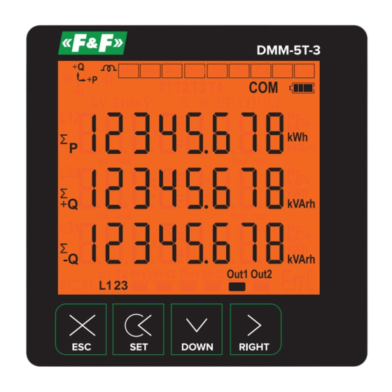
DMM-5T-3 User manual 7. Introduction of screen Number Description Indicates the unit of the value Indicates which phase the value belongs to Indicates displayed values: V – voltage, I – current, F – frequency, S – apparent power, P – active power, PF – power factor, THD-I – total current harmonics, THD-V –... -
Page 6: Introduction Of Buttons
DMM-5T-3 User manual Symbol Description Symbol Description Indicates that the values shown are Din1: There is voltage (1) minimum Indicates that the values shown are Din1: There is no voltage (0) maximum Indicates that the values shown are Out1: Relay 1 is pulled... -
Page 7: Progress On Screen Information
DMM-5T-3 User manual 9. Progress on screen information Screen Description Indicates phase-neutral voltage. Fig. 4. When you press right button, the Figure-5 appears on the screen. Indicates minimum (Min) voltage values of phase-neutral voltage. Fig. 5. When you press right button, the Figure-6 appears on the screen. - Page 8 DMM-5T-3 User manual Screen Description Shows the average (Ave) values of the phase-phase voltage. Fig. 14. When you press right button, the Figure-15 appears on the screen. Illustrates the date and time, in which phase-phase voltage goes under 90% (<Vtr×230×0.9) of the nominal voltage values (lowest). When you press the ri- Fig.
- Page 9 DMM-5T-3 User manual Screen Description It shows the active power (P) values for each zone. Fig. 25. When you press the right button, the screen will show Figure-26. It shows the maximum active power (P) values for each zone. Fig. 26.
- Page 10 DMM-5T-3 User manual Screen Description It shows maximum (Max) apparent power (S) value which belongs to each Fig. 36. phase. When the right button is pressed, the Figure-37 comes to the screen. It shows average (Ave) apparent power (S) which belongs to each phase.
- Page 11 DMM-5T-3 User manual Screen Description Voltage harmonics values of up to 55th harmonics are displayed on each screen, with 3 values per screen. . When you press the right button, the values Fig. 47. of the L2 and L3 phases are displayed on the screen respectively.
-
Page 12: Fast Forwarding Of Screen Information
DMM-5T-3 User manual 10. Fast forwarding of screen information Fig. 4. Voltage values between phase-neutral Fig. 42. Frequency values Fig. 11. Phase-to-phase voltage values Fig. 43. Total voltage harmonic values Fig. 18. Current values Fig. 49. Total energy (active and reactive) values Fig. -
Page 13: Menu Structure
DMM-5T-3 User manual 11. Menu structure Fig. 59. Enter the current transformer ratio Fig. 64. Determine the connection type Fig. 60. Enter the voltage transformer ratio Fig. 65. Set the date Fig. 61. Make communication settings Fig. 66. Set the time Fig. -
Page 14: Setting The Current Transformer Ratio
DMM-5T-3 User manual 11.1. Setting the current transformer ratio To change the current transformer ratio, press the set button while the Figure-58 is on the screen. Figure-69 comes to the screen. Press right button to move between digits. Press the down key to change the value of the digit. -
Page 15: Enter Password Value
DMM-5T-3 User manual 11.5. Enter password value In order to change password; press set button while Figure-63 is on the screen . The Figure-73 comes to the screen. In order to pass through steps; press the button on the right. -
Page 16: Task Assignment To Relay 1 And Relay 2
DMM-5T-3 User manual 11.9. Task assignment to relay 1 and relay 2 To assign the task to relay 1, press the set key, when Figure-77 is on the screen. There are 3 settings; these are Parameter (PAr), Function (Valued) and Value (VAL). -
Page 17: Menu Values Table
DMM-5T-3 User manual 13. Menu values table Parameter Factory Parameter Unit Minimum value Maximum value number value Current transformer ratio – 5000 Voltage transformer ratio – 999.9 Baudrate 9600 1200 115200 – Stop bits – – – – Data bits –... -
Page 18: Technical Data
DMM-5T-3 User manual 14. Technical data Operating voltage 85÷240 V AC Operating frequency 50/60 Hz Operating power <10 VA Operating temperature -20÷55°C Input voltage 5÷330 V AC Voltage measuring range 1 V÷600 kV Input current 1 mA÷5,5 A Current measuring range 1 mA÷50.000 A... - Page 19 DMM-5T-3 User manual Appendix 1 DMM-5T-3: List of registers with measurement results Address Address Data Read/ Parameter Multiplier Unit Real value (Dec) (Hex) type Write Current 4000 Unsigned 16-bit Data 1 .. 5000 transformer ratio Voltage 4001 Unsigned 16-bit Data * 0.1 1,0 ..
- Page 20 DMM-5T-3 User manual Appendix 1 cont. DMM-5T-3: List of registers with measurement results Address Address Data Read/ Parameter Multiplier Unit Real value (Dec) (Hex) type Write 4035 Minute Unsigned 16-bit Data 0 .. 59 4036 Second Unsigned 16-bit Data 0 .. 59...
- Page 21 DMM-5T-3 User manual Appendix 1 cont. DMM-5T-3: List of registers with measurement results Address Address Data Read/ Parameter Multiplier Unit Real value (Dec) (Hex) type Write 4070 Total capacitive Unsigned 32-bit Data Varh 0 .. Max energy 4071 4072 L1 apparent...
- Page 22 DMM-5T-3 User manual Appendix 2 DMM-5T-3: List of registers with measurement results Address Address Data Read/ Parameter Multiplier Unit Real value (Dec) (Hex) type Write 2000 L1 THDV Unsigned 16-bit Data * 0.1 0,0 ..400,0 2001 L2 THDV Unsigned 16-bit Data * 0.1...
- Page 23 DMM-5T-3 User manual Appendix 2 cont. DMM-5T-3: List of registers with measurement results Address Address Data Read/ Parameter Multiplier Unit Real value (Dec) (Hex) type Write 2320 IL2 63.Harmonic Unsigned 16-bit Data * 0.1 0,0 ..400,0 2321 IL3 2.Harmonic Unsigned 16-bit Data * 0.1...
Need help?
Do you have a question about the DMM-5T-3 and is the answer not in the manual?
Questions and answers