Table of Contents
Advertisement
Quick Links
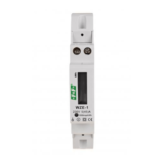
WZE-1
Electricity consumption
meter, single-phase
Do not dispose of this device in the trash along with other waste!
According to the Law on Waste, electro coming from households free of charge and can
give any amount to up to that end point of collec� on, as well as to store the occasion of
the purchase of new equipment (in accordance with the principle of old-for-new, regard-
less of brand). Electro thrown in the trash or abandoned in nature, pose a threat to the
environment and human health.
Compliance
Directive MID
Certificate number
Purpose
The WZE-1 is a static (electronic) calibrated single-phase AC elec-
tricity consumption meter in a direct system.
Functioning
Under the influence of the flowing current and applied voltage,
a special electronic system generates impulses in a quantity pro-
portional to the electricity consumed. Power consumption is in-
dicated by a flashing LED. The number of pulses is converted into
energy consumed and its value is indicated on a segmented LCD.
Decimal digits indicate the hundredth of kWh (0.01 kWh = 10
Wh).
F&F Filipowski sp. j.
Konstantynowska 79/81, 95-200 Pabianice, POLAND
phone/fax (+48 42) 215 23 83 / (+48 42) 227 09 71
www.fif.com.pl; e-mail: biuro@fif.com.pl
2014/32/EU
TCM 221/12-4971
- 1 -
Advertisement
Table of Contents

Related Manuals for F&F WZE-1


Summary of Contents for F&F WZE-1
- Page 1 2014/32/EU Certificate number TCM 221/12-4971 Purpose The WZE-1 is a static (electronic) calibrated single-phase AC elec- tricity consumption meter in a direct system. Functioning Under the influence of the flowing current and applied voltage, a special electronic system generates impulses in a quantity pro- portional to the electricity consumed.
- Page 2 Pulse output The indicator has a SO+ SO- pulse output. This allows you to con- nect another pulse device (SO) that reads impulses generated by the meter. No additional device is required for the correct operation of the meter. Sealing The meter has the option of sealing the input and output termi- nals, preventing the meter from being bypassed.
- Page 3 Description of the front of the device - 3 -...
- Page 4 Dimensions - 4 -...
- Page 5 Connection diagram phase wire – power supply phase wire – output 4, 6 neutral wire pulse output (+) pulse output (–) - 5 -...
- Page 6 Mounting 1. Disconnect the power supply. 2. Mount the meter on a rail in the distribution box. 3. Connect the input phase to terminal 1. 4. Connect the N wire to terminal 4. 5. Connect the measured circuit or a single receiver to terminal 3 (output phase L) and terminal 6 (N).
- Page 7 Techniccal data cont. terminal 6 mm² screw terminals dimensions 1 module (18 mm) mounting on TH-35 rail protection level IP20 Warranty F&F products are covered by a 24-month warranty from the date of purchase. The warranty is only valid with proof of purchase. Contact your dealer or contact us directly.
- Page 8 General work safety conditions » Please read the instructions carefully before installation. » The device should be installed and operated by qualified per- sonnel who are familiar with its design, operation, and asso- ciated risks. » Do not install a meter that is damaged or incomplete. »...
Need help?
Do you have a question about the WZE-1 and is the answer not in the manual?
Questions and answers