Advertisement
Quick Links
DMA-1 CT TrueRMS
Current intensity indicator,
1-phase
Do not dispose of this device in the trash along with other waste! According to the
Law on Waste, electro coming from households free of charge and can give any amo-
unt to up to that end point of collec� on, as well as to store the occasion of the purchase
of new equipment (in accordance with the principle of old-for-new, regardless of brand).
Electro thrown in the trash or abandoned in nature, pose a threat to the environment
and human health.
Purpose
The DMA-1 CT is a 1-phase current intensity indicator, adapted
for measurement in an indirect circuit using current transfor-
mers with an output current of 5 A.
The sensor correctly measures the true rms value of the
current (TrueRMS), even in the case of a distorted (de-
formed) current waveform.
Functioning
The indicator continuously measures the TrueRMS current value,
the result of which is shown on a 3-digit segment display on the
facade of the unit.
The indicator allows the value of connected current transfor-
mers to be set, so that the value shown on the display corre-
sponds to the actual current value.
The DMA-1 CT is suitable for mounting in a switchgear directly
on a 35 mm DIN rail.
F&F Filipowski L.P.
Konstantynowska 79/81, 95-200 Pabianice, POLAND
phone/fax (+48 42) 215 23 83 / (+48 42) 227 09 71
www.fif.com.pl; e-mail: biuro@fif.com.pl
- 1 -
Advertisement

Related Manuals for F&F DMA-1 CT TrueRMS


Summary of Contents for F&F DMA-1 CT TrueRMS
- Page 1 Konstantynowska 79/81, 95-200 Pabianice, POLAND phone/fax (+48 42) 215 23 83 / (+48 42) 227 09 71 www.fif.com.pl; e-mail: biuro@fif.com.pl DMA-1 CT TrueRMS Current intensity indicator, 1-phase Do not dispose of this device in the trash along with other waste! According to the Law on Waste, electro coming from households free of charge and can give any amo- unt to up to that end point of collec�...
-
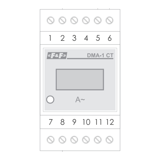
Page 2: Front Description
Front description LCD display SET button - 2 -... - Page 3 Mounting 1. Switch off power supply. 2. Install indicator on DIN rail. 3. Connect the indicator according to the connection diagram: » Connect the power supply of the indicator (230 V AC) to terminals 5 and 6; » The current transformer output is connected to terminals 2 and 8.
-
Page 4: Wiring Diagram
Wiring diagram - 4 -... - Page 5 L phase – current input (S1 terminal of the transformer) power supply 230 V AC (phase wire) power supply 230 V AC (neutral wire) L phase – current output (S2 terminal of the transformer) Configuration In order for the indicator to show current values, the cur- rent transformers connected to the indicator must first be programmed.
- Page 6 Technical data power supply 165÷265 V AC/DC measurement indirect (transformer 5 A) number of measurement channels measured value TrueRMS value AC current frequency 45÷55 Hz maximum current measurement range 0÷5 A maximum momentary overload 20 A/1 s indication accuracy reading accuracy measurement range <100 A 0.1 A measurement range ≥100 A...
-
Page 7: Warranty
Warranty F&F products are covered by a 24-month warranty from the date of purchase. The warranty is only valid with proof of purchase. Contact your dealer or contact us directly. CE declaration F&F Filipowski sp. L.P. declares that the device is in conformity with the essential requirements of The Low Voltage Directive (LVD) 2014/35/EU and the Electromagnetic Compatibility (EMC) Directive 2014/30/UE.
Need help?
Do you have a question about the DMA-1 CT TrueRMS and is the answer not in the manual?
Questions and answers