Table of Contents
Advertisement
Quick Links
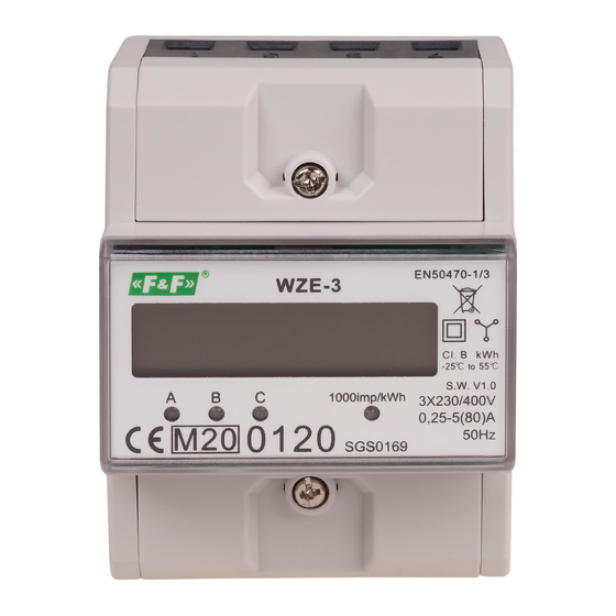
WZE-3
Electric energy meter,
3-phase
Do not dispose of this device in the trash along with other waste!
According to the Law on Waste, electro coming from households free of charge and can
give any amount to up to that end point of collec� on, as well as to store the occasion of
the purchase of new equipment (in accordance with the principle of old-for-new, regard-
less of brand). Electro thrown in the trash or abandoned in nature, pose a threat to the
environment and human health.
Compliance
MID Directive
Certificate number
Purpose
The WZE-3 is a static (electronic) calibrated electricity meter of
three-phase alternating current in a direct system.
Functioning
A special electronic system under the influence of current flow
and applied voltage in each phase, generates pulses in propor-
tion to the electricity consumed in this phase. Phase energy con-
sumption is indicated by flashing the corresponding LED (A, B,
C). The sum of the pulses of the three phases is indicated by a
flashing LED shall be converted to energy, taken throughout the
three-phase system, and its value is determined by the segment
LCD display.
Decimal represent the hundredths (0.01 kWh = 10 Wh).
F&F Filipowski sp. j.
Konstantynowska 79/81, 95-200 Pabianice, POLAND
phone/fax (+48 42) 215 23 83 / (+48 42) 227 09 71
www.fif.com.pl; e-mail: biuro@fif.com.pl
2014/32/EU
0120/SGS/0169
- 1 -
Advertisement
Table of Contents

Related Manuals for F&F WZE-3


Summary of Contents for F&F WZE-3
- Page 1 2014/32/EU Certificate number 0120/SGS/0169 Purpose The WZE-3 is a static (electronic) calibrated electricity meter of three-phase alternating current in a direct system. Functioning A special electronic system under the influence of current flow and applied voltage in each phase, generates pulses in propor- tion to the electricity consumed in this phase.
-
Page 2: Measured Value
Measured value Active energy consumed [kWh] Pulse output The indicator has a pulse output. This allows you to connect a pulse meter-reading pulses generated by the counter. For proper operation of the indicator is not required to connect additional devices. Meter number The meter is marked with individual serial number allowing its unambiguous identification. - Page 3 Sealing The meter has sealable input and output terminal covers to pre- vent any attempts to bypass the meter. - 3 -...
-
Page 4: Description Of Terminals
Mounting 1. Disconnect the power supply. 2. The indicator mounted on a rail in the distribution box. 3. Using a screwdriver, remove the screws and remove the front shield meter terminals. 4. Connect power to terminals 1 (L1 IN), 3 (L2 IN), 5 (L3 IN). 5. -
Page 5: Wiring Diagram
Wiring diagram - 5 -... - Page 6 Technical data installation 4-wire rated voltage 3×230/400 V minimum measured current 0.04 A base current 0.25÷5 A maximum current 80 A voltage measuring range 160÷265 V measurement accuracy (EN50470-1/3) class B rated frequency 50 Hz insulation protection class housing PC+ABS material own power consumption <10 VA;...
-
Page 7: Warranty
Dimensions Warranty F&F products are covered by a 24-month warranty from the date of purchase. The warranty is only valid with proof of purchase. Contact your dealer or contact us directly. CE declaration F&F Filipowski sp. j. declares that the device is in conformity with the essential requirements of The Low Voltage Directive (LVD) 2014/35/EU and the Electromagnetic Compatibility (EMC) Directive 2014/30/UE. - Page 8 General work safety conditions » Please read the instructions carefully before installation. » The device should be installed and operated by qualified per- sonnel who are familiar with its design, operation, and asso- ciated risks. » Do not install a meter that is damaged or incomplete. »...
Need help?
Do you have a question about the WZE-3 and is the answer not in the manual?
Questions and answers