Table of Contents
Advertisement
Quick Links
DMA-3 CT TrueRMS
Current intensity indicator,
3-phase
Do not dispose of this device in the trash along with other waste! According to the
Law on Waste, electro coming from households free of charge and can give any amo-
unt to up to that end point of collec� on, as well as to store the occasion of the purchase
of new equipment (in accordance with the principle of old-for-new, regardless of brand).
Electro thrown in the trash or abandoned in nature, pose a threat to the environment
and human health.
Purpose
The DMA-3 CT is a 3-phase current intensity indicator, adapted
for measurement in an indirect circuit using current transfor-
mers with an output current of 5 A.
The sensor correctly measures the true rms value of the
current (TrueRMS), even in the case of a distorted (de-
formed) current waveform.
Functioning
The indicator continuously measures the RMS current value, the
result of which is shown on a 3-row, 3-digit segment display on
the facade of the unit.
The indicator allows the value of connected current transfor-
mers to be set, so that the value shown on the display corre-
sponds to the actual current value.
The DMA-3 CT is suitable for mounting in a switchgear directly
on a 35 mm DIN rail.
F&F Filipowski L.P.
Konstantynowska 79/81, 95-200 Pabianice, POLAND
phone/fax (+48 42) 215 23 83 / (+48 42) 227 09 71
www.fif.com.pl; e-mail: biuro@fif.com.pl
- 1 -
Advertisement
Table of Contents

Related Manuals for F&F DMA-3 CT TrueRMS


Summary of Contents for F&F DMA-3 CT TrueRMS
- Page 1 Konstantynowska 79/81, 95-200 Pabianice, POLAND phone/fax (+48 42) 215 23 83 / (+48 42) 227 09 71 www.fif.com.pl; e-mail: biuro@fif.com.pl DMA-3 CT TrueRMS Current intensity indicator, 3-phase Do not dispose of this device in the trash along with other waste! According to the Law on Waste, electro coming from households free of charge and can give any amo- unt to up to that end point of collec�...
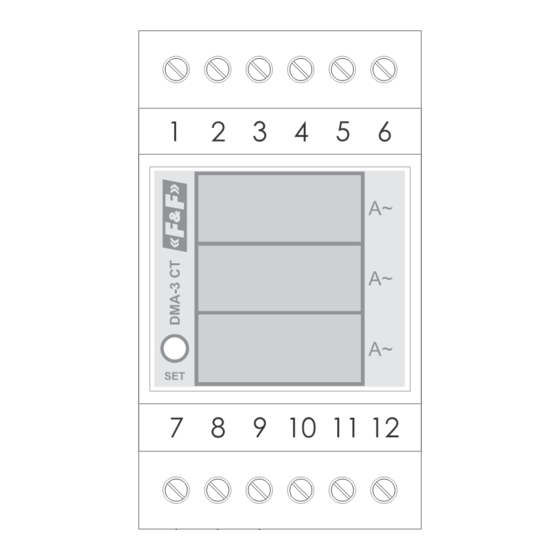
- Page 2 Front description L1 phase LCD display L2 phase LCD display L3 phase LCD display SET button - 2 -...
- Page 3 Mounting 1. Switch off power supply. 2. Install indicator on DIN rail. 3. Connect the indicator according to the connection diagram: 4. Connect the power supply of the indicator (230 V AC) to termi- nals 5 and 6; connect the current transformer output to termi- nals 1-7 (phase L1), 2-8 (phase L2), 3-9 (phase L3).
- Page 4 Wiring diagram - 4 -...
- Page 5 L1 phase - current input (S1 terminal of the transformer) L2 phase - current input (S1 terminal of the transformer) L3 phase - current input (S1 terminal of the transformer) not used power supply 230 V AC (phase wire) power supply 230 V AC (neutral wire) L1 phase - current output (S2 terminal of the transformer) L2 phase - current output (S2 terminal of the...
- Page 6 Current ratio programming 1. Press and hold down the SET button located on the facade of the indicator. 2. Release the button after a minimum of 5 seconds. 3. Use successive short presses of the SET button to set the de- sired current ratio value.
- Page 7 terminal 2,5 mm² screw terminals (cord) 4.0 mm² screw terminals (wire) tightening torque 0.5 Nm working temperature -25÷50°C dimensions 3 modules (52.5 mm) mounting on TH-35 rail ingress protection IP20 Gwarancja Warranty F&F products are covered by a 24-month warranty from the date of purchase.
Need help?
Do you have a question about the DMA-3 CT TrueRMS and is the answer not in the manual?
Questions and answers