Table of Contents
Advertisement
Quick Links
Advertisement
Table of Contents

Related Manuals for Vaisala RS41


Summary of Contents for Vaisala RS41
- Page 1 USER'S GUIDE Ozone Sounding with Vaisala Radiosonde RS41 M211486EN-A...
- Page 2 The contents are subject to change without prior notice. This manual does not create any legally binding obligations for Vaisala towards customers or end users. All legally binding obligations and agreements are included exclusively in the applicable supply contract or the General Conditions of Sale and General Conditions of Service of Vaisala.
-
Page 3: Table Of Contents
Equipment and Material Needed ..... 25 Vaisala Ozone Sounding Startup Kit ....26 Ozonizer/Test Unit TSC-1 . - Page 4 User’s Guide ______________________________________________________________________ Preparation Steps .......43 Preparations on the Day of Release ....46 Preparation Steps .
- Page 5 Archived Ozone Data in MW41 ..... 108 Additional Sensor Data from RS41 ....109 Additional Sensor Data from RS92 .
- Page 6 User’s Guide ______________________________________________________________________ 4 ____________________________________________________________________M211486EN-A...
- Page 7 OIF411 Dimensions ....... . . 23 Figure 7 RS41 Additional Sensor Interface ..... . 24 Figure 8 Ozonizer/Test Unit TSC-1 .
- Page 8 Pushing the Holder into Place ......72 Figure 44 Radiosonde RS41 Attached to the Holder ....72 Figure 45 SPC Ozone Sensor inside the Flight Box.
- Page 9 OIF411 Terminals ........22 Table 4 Electrical Interface of RS41 and the Additional Sensor ..24 Table 5 Ozone Sounding Startup Kit .
- Page 10 User’s Guide ______________________________________________________________________ 8 ____________________________________________________________________M211486EN-A...
-
Page 11: Chapter 1 General Information
RS41, and an ozone sensor. The manual describes: The preparation of the ozone sensor with RSA411 Ozone Interface Kit and Radiosonde RS41. For a list of the ozone sensor manufacturers’ manuals, see topic Related Manuals on page Sounding preparations before the launch. See Chapter... - Page 12 Product and System Component Overview on page introduces the product components. Chapter 3, Constructing an Ozone Sounding on page 41, describes the sounding preparations with Vaisala Radiosonde RS41, the ozone sensor, and the ground equipment. Chapter 4, Ozone Calculation on page 85, describes ozone calculation in detail.
-
Page 13: Version Information
May 2014. First version. Related Manuals Table 2 Related Manuals Manual Code Description M211667EN Vaisala Radiosonde RS41-SG User’s Guide DOC-0336 Droplet Measurement Technologies Model Z ECC Ozonesondes Operator Manual SPC-6A Manual © Science Pump Corporation Operator’s Manual Model 6A ECC Ozonesonde SPC TSC-1 ©... -
Page 14: Product-Related Safety Precautions
User’s Guide ______________________________________________________________________ Product-Related Safety Precautions Radiosonde RS41 has been tested for safety and approved as shipped from the factory. Note the following precautions: WARNING Conduct soundings in a safe environment and in accordance with all applicable restrictions and regulations. -
Page 15: Lithium Battery-Related Precautions
DO NOT THROW WATER ON A BURNING BATTERY. A fire extinguisher must be used. Transporting RS41 Radiosondes with Lithium Batteries RS41 radiosondes with lithium batteries are classified as: UN 3091 Lithium metal batteries contained in equipment Consignments must be packed, labeled, and documented according to the IATA packing instructions. -
Page 16: Figure 1 Lithium Battery Handling Label
User’s Guide ______________________________________________________________________ shipping package must be used for transport, and it already has the lithium battery handling label. The consignment must include a document indicating the lithium content, describing proper handling and procedures for damaged packages, and a telephone number for additional information. The original radiosonde consignment includes a SHIPPER'S DECLARATION FOR ARTICLES NOT REGULATED AS DANGEROUS GOODS, which should be reused for this purpose... -
Page 17: Esd Protection
Chapter 1 ________________________________________________________ General Information ESD Protection Electrostatic Discharge (ESD) can cause immediate or latent damage to electronic circuits. Vaisala products are adequately protected against ESD for their intended use. However, it is possible to damage the product by delivering electrostatic discharges when touching, removing, or inserting any objects inside the equipment housing. -
Page 18: Product Returns
User’s Guide ______________________________________________________________________ Product Returns If the product must be returned for service, see www.vaisala.com/ returns. For contact information of Vaisala Service Centers, see www.vaisala.com/servicecenters. 16 ___________________________________________________________________M211486EN-A... -
Page 19: Product And System Component Overview
This chapter introduces the product and system components in more detail. Introduction to Ozone Sounding An ozone sounding with RS41 consists of an ozone sensor unit, RSA411 Ozone Interface Kit, and RS41 radiosonde. These are described in the sections below. Other equipment needed is also explained. -
Page 20: Ozone Sensor Unit
User’s Guide ______________________________________________________________________ Ozone Sensor Unit The ozone sensor unit is either of the following: Science Pump Corporation (SPC) Model ECC-6A ozone sensor Droplet Measurement Technologies (DMT) Model Z ozone sensor The sensors are based on chemical reaction cells. The type of the sensors is electrochemical concentration cell (ECC). -
Page 21: Figure 2 Spc Ecc-6A Ozone Sensor Parts
Figure 2 SPC ECC-6A Ozone Sensor Parts 0410-112 The following numbers refer to Figure 2 on page Gas sampling pump Ozone sensor cathode Ozone sensor anode Wires for interface Air intake tube Motor Connector for pump battery VAISALA _______________________________________________________________________ 19... -
Page 22: Ozone Interface Kit Rsa411
User’s Guide ______________________________________________________________________ Ozone Interface Kit RSA411 The RSA411 kit is used with Radiosonde RS41 and Science Pump Corporation’s (SPC) ECC type sensors Model ECC6A, or Droplet Measurement Technologies (DMT) Model Z. The kit contains the items listed below. The numbers refer to... -
Page 23: Ozone Interface Board Oif411
Ozone Interface Board OIF411 Ozone Interface Board OIF411 has four dedicated channels (ozone sensor current and temperature, battery voltage, and ozone pump current), and an additional voltage measurement channel for other purposes. Figure 4 Ozone Sensor Interface Board OIF411 1310-028 VAISALA _______________________________________________________________________ 21... -
Page 24: Figure 5 Oif411 Terminals Marked On Sticker
User’s Guide ______________________________________________________________________ The terminals on OIF411 are marked with a sticker attached on the card. Figure 5 on page 22 for details. The numbers in the figure refer to Table 3 on page Figure 5 OIF411 Terminals Marked on Sticker Table 3 OIF411 Terminals Number... -
Page 25: Figure 6 Oif411 Dimensions
Chapter 2 ______________________________________ Product and System Component Overview Figure 6 OIF411 Dimensions 1401-009 VAISALA _______________________________________________________________________ 23... -
Page 26: Radiosonde Rs41 Additional Sensor Interface
Table 4 on page 24 for details on the RS41 electrical interface and and the additional sensor. Figure 7 RS41 Additional Sensor Interface 1311-203 Table 4 Electrical Interface of RS41 and the Additional Sensor Radiosonde Additional Sensor Name Function Name... -
Page 27: Equipment And Material Needed
Equipment and Material Needed Several items are needed to prepare the ozone sensor and the radiosonde for a flight. The items listed below are included in the Vaisala Ozone Sounding Startup Kit and they are explained in more detail in the... -
Page 28: Vaisala Ozone Sounding Startup Kit
Vaisala Ozone Sounding Startup Kit Vaisala part number 25820OS. Vaisala Ozone Sounding Startup Kit is used when preparing a new ozone sounding site. The kit includes materials and equipment for the sounding preparations. A list of the items and their part numbers are... -
Page 29: Ozonizer/Test Unit Tsc-1
Figure 8 Ozonizer/Test Unit TSC-1 1006-003 NOTE Vaisala recommends adding a digital ampere meter with a minimum resolution of 0.01 uA beside Ozonizer TSC-1, and checking the current from the digital ampere meter instead of the analog meter on TSC-1. - Page 30 Table 1 on page 11 for a list of related manuals. The following spare parts are available for TSC-1: Calibrator ECC ozone sensor, OTU-15. Vaisala part number 18955. Internal ozone filter, OTU-17. Vaisala part number 18960. Other spare parts mentioned in the TSC-1 manual are also available.
-
Page 31: Figure 9 Ec Black Bench O3S Tester Made By Ec
Chapter 2 ______________________________________ Product and System Component Overview Figure 9 EC Black Bench O3S Tester Made by EC 1403-002 Figure 10 EC White Bench O3S Tester Made by Droplet 1403-003 Measurement Technologies VAISALA _______________________________________________________________________ 29... -
Page 32: Ozone Destruction Filter
119. Table 6 Equipment Required for Ozone Destruction Filter Item Required Vaisala Part Number Particle and ozone filter: Mine Safety Appliances (MSA) 234561 (1 pc) Company. Delivered by MSA as a single cartridge (part number 815185). Funnel, 75 mm in diameter, tube diameter 8 mm, glass... -
Page 33: Pump Test Unit
Connector tube 1: soft vinyl tube approximately 60 cm 12642OS (set of long, I.D. 1/8" (3.2 mm), O.D. 1/4" (6.4 mm) tubes) Connector tube 2: soft silicon tube approximately 2 cm 12642OS (set of long, inner diameter 2 mm, outer diameter 4 mm tubes) VAISALA _______________________________________________________________________ 31... -
Page 34: Figure 12 Vacuum/Pressure Gauge
User’s Guide ______________________________________________________________________ Table 7 Equipment Required for Pump Test Unit (Continued) Item Required Vaisala Part Number Connection tube 3: cut a piece of tubing from EEC 17348S (by the sensor air inlet tubes to a length of approximately 3 cm, meter) or SPC or order separately. -
Page 35: Laboratory Ware Set
Table 8 on page 33 is useful and can easily be obtained from any laboratory ware dealer. The set can also be ordered from Vaisala by referring to the part numbers listed in the table. Table 8 Laboratory Ware Needed... -
Page 36: Ozone Chemicals
User’s Guide ______________________________________________________________________ Table 8 Laboratory Ware Needed (Continued) Item Pieces Vaisala Part Number Syringes with needle Disposable; total volume 3 ml, division. 0.1 ml (at least 0.5 ml). Plastic (Teflon) 2 pcs, Syringe 12736 2 pcs, Syringe needle 12737... -
Page 37: Air Flow Meter
Never operate the pump without the ozone destruction filter or purified air. Do not use a sensor loaded with solutions if the sensor is not connected to a powered interface (or if the anode and cathode wires are connected). VAISALA _______________________________________________________________________ 35... - Page 38 User’s Guide ______________________________________________________________________ Arrange the air flow meter as shown in Figure 13 on page 37. The procedure for air flow measurement is described below. The numbers within brackets refer to the items in Figure 13 on page Fill the rubber bulb (4) and the flow meter tube with soap solution (8) almost up to the filling tube of the flow meter tube.
-
Page 39: Figure 13 Air Flow Rate Measurement
Chapter 2 ______________________________________ Product and System Component Overview Figure 13 Air Flow Rate Measurement 1006-004 The following numbers refer to Figure 13 on page Stand Bosshead Connector tube 1 Rubber bulb Flow meter tube Clamp Connector tube 2 Dishwashing liquid Connector tube 3 VAISALA _______________________________________________________________________ 37... -
Page 40: Other Equipment And Material
User’s Guide ______________________________________________________________________ Other Equipment and Material Balance The balance must fulfill the following requirements: Measurement range must be from 0 to 500 g. Accuracy required is 0.01 g. Thermometer A thermometer is needed for measuring air temperature. It can be a mercury thermometer or an electrical thermometer. -
Page 41: Expendables And Spare Parts
The list of expendables includes at least: Radiosondes, interfaces Sounding accessories (for example, balloons) Ozone solution chemicals Syringes, needles Protective gloves Triple-distilled or ion-changed water See also Appendix E Checklist for Equipment and Supplies for Flight Preparations on page 117. VAISALA _______________________________________________________________________ 39... - Page 42 User’s Guide ______________________________________________________________________ 40 ___________________________________________________________________M211486EN-A...
-
Page 43: Constructing An Ozone Sounding
Preparing an ozone sounding consists of the following steps. See the sections below for more information. Preparations 7 to 3 Days Prior to Release on page Preparations on the Day of Release on page Preparations Just Before Release (2 - 0 Hours) on page VAISALA _______________________________________________________________________ 41... - Page 44 : after 10 minutes of zero air after exposure of ozone (5 µA ozone equivalent of 170 - 180 ppbv). : at launch site after 10 minutes of zero air. NOTE equals to Vaisala I , used in Vaisala scripts. 42 ___________________________________________________________________M211486EN-A...
-
Page 45: Preparations 7 To 3 Days Prior To Release
Write down the following information: Date: _______ Station: _________ Operator: __________ Check the label on the flight box and record the information here. Ozone sensor number: Manufacturer: Date of manufacture: Pump pressure:____________ in Hg VAISALA _______________________________________________________________________ 43... - Page 46 User’s Guide ______________________________________________________________________ Pump voltage:____________ V DC Pump current:____________ mA Flow rate:_____________s/100 ml Connect the ozone sensor to the ozonizer (motor, output, sensor leads). Turn on the ozonizer. Record I before applying any ozone to the sensor: _____________µA Condition the pump and the dry sensor with HI O for 30 minutes.
- Page 47 13. Put the ozone sensor back to the flight box and store it in a dark, clean-air environment at a temperature of 20 ... 25 °C until it is used. After these preparations, a sensor cleaning process takes place, whereby both half cells (anode and cathode) and ionbridge get in balance. VAISALA _______________________________________________________________________ 45...
-
Page 48: Preparations On The Day Of Release
User’s Guide ______________________________________________________________________ Preparations on the Day of Release Preparation Steps NOTE The CAL measurements are applicable when SPC’s TSC-1 Ozonizer/ Test unit is used. They can be ignored with DMT’s ozonizer. Write down the following information: Date: ________ Station :_________ Operator: __________ Ozonesonde number: _______________ Manufacturer: _______________ Date of manufacture: _______________... - Page 49 See Science Pump Corporation’s Operator’s Manual for further instructions.) = ________ <0.20 (i )______ = ________ <0.20 (i )______ or, alternatively with DMT ozonizer: = _______ <0.20 (i VAISALA _______________________________________________________________________ 47...
-
Page 50: Preparations Just Before Release (2 - 0 Hours)
Table 11 Workflow for Ozone Sounding Preparations 45 Minutes Before Launch Time to Ozone Sensor Interface Radiosonde Sounding Balloon and Launch in OIF411 RS41 Software MW41 Accessories Minutes Select battery Attach interface Attach Start MW41 Fill the balloon type and any... -
Page 51: Starting Preparations
Radiosonde holder with three plastic dowels and three screws, included in Ozone Interface Kit RSA411. Figure 14 on page 50 shows how the radiosonde holder is attached to the flight box wall. See also the steps below. VAISALA _______________________________________________________________________ 49... -
Page 52: Figure 14 Radiosonde Holder Attachment
In the figures presented in this section, the holder is positioned according to Vaisala recommendation, according to which the radiosonde sensor boom is above the flight box wall and the holder is attached on top of the sticker. -
Page 53: Figure 15 Radiosonde Holder Measurements (A) And Position (B)
Chapter 3 _____________________________________________ Constructing an Ozone Sounding Figure 15 Radiosonde Holder Measurements (a) and Position 1402-102 VAISALA _______________________________________________________________________ 51... -
Page 54: Figure 16 Marking The Positions Of The Holder Screws
User’s Guide ______________________________________________________________________ The holder is attached on top of the sticker on the flight box wall. Press the radiosonde holder against the flight box wall and mark the holder screw positions with a pen. Figure 16 Marking the Positions of the Holder Screws 1403-167 52 ___________________________________________________________________M211486EN-A... -
Page 55: Attaching Oif411 To Spc's Ozone Sensor Frame
OIF411. For instructions on attaching OIF411 to Droplet Measurements Technologies (DMT) Model Z ozone sensor frame, see section Attaching OIF411 to DMT’s Ozone Sensor Frame on page VAISALA _______________________________________________________________________ 53... -
Page 56: Figure 18 Attaching Oif411 To Ozone Sensor
User’s Guide ______________________________________________________________________ CAUTION Keep the sensor in an upright position. The sensor contains liquid. Figure 18 Attaching OIF411 to Ozone Sensor The following numbers refer to Figure 18 on page Wing nuts Ozone sensor frame OIF411 Take these steps to connect the ozone sensor frame and Ozone Interface Board OIF411. -
Page 57: Figure 19 Wing Nuts On The Back Of Oif411
Chapter 3 _____________________________________________ Constructing an Ozone Sounding Figure 19 Wing Nuts on the Back of OIF411 1310-101 Figure 20 OIF411 Being Attached to the Ozone Sensor 1310-102 Frame VAISALA _______________________________________________________________________ 55... -
Page 58: Attaching Oif411 To Dmt's Ozone Sensor Frame
User’s Guide ______________________________________________________________________ Tighten the wing nuts. Figure 21 OIF411 Wing Nuts Tightened Attaching OIF411 to DMT’s Ozone Sensor Frame For instructions on attaching OIF411 to Droplet Measurements Technologies’ (DMT) ozone sensor frame, see the steps below. In addition to OIF411 and the ozone sensor frame, you need the following equipment: Two M3 nuts included in RSA411 Ozone Interface Kit Drill with applicable drill bits... -
Page 59: Figure 22 Droplet Measurements Model Z Sensor
Take these steps to connect the ozone sensor frame and Ozone Interface Board OIF411. Remove the wing nuts attached to OIF411. Use a drill to make the holes in the ozone sensor frame bigger. Figure 23 Drilling the Ozone Sensor Frame Holes 1405-007 VAISALA _______________________________________________________________________ 57... -
Page 60: Connecting Ozone Sensor Wires To Oif411
User’s Guide ______________________________________________________________________ Attach OIF411 to the ozone sensor frame with the two M3 hex nuts, a screw driver and a socket wrench. Tighten the nuts. Figure 24 Ozone Sensor Attached to the DMT Frame with M3 Nuts Connecting Ozone Sensor Wires to OIF411 Connect the ozone sensor wires to Ozone Interface Board OIF411. -
Page 61: Figure 25 Oif411 Terminals Marked On Sticker
Number Connection Cable Code Radiosonde interface CBL210224 Add-on sensor IN for optional XDATA sensors Pump motor CBL210282 Ozone pump motor battery CBL210225 Heating battery CBL210295 Extra terminal SPC sensor W = white cable B = blue cable VAISALA _______________________________________________________________________ 59... -
Page 62: Figure 26 Connecting Sensor Wires To Oif411
User’s Guide ______________________________________________________________________ The white wire from the anode is connected to the terminal on the corner of the interface marked with W. The blue wire from the cathode is connected to the terminal marked with B. Figure 26 Connecting Sensor Wires to OIF411 60 ___________________________________________________________________M211486EN-A... -
Page 63: Preparing The Radiosonde And Oif411
The pump is allowed to be used only with NO-OZONE, or when the destruction filter is connected. Never use HI-OZONE. Connecting Ozone Sensor Pump to OIF411 Cable needed: CBL210282 Connect the cable to the OIF411 terminal marked Pump. Figure 27 Connecting Ozone Sensor Pump Cable VAISALA _______________________________________________________________________ 61... -
Page 64: Connecting Ozone Pump Battery To Oif411
User’s Guide ______________________________________________________________________ Connecting Ozone Pump Battery to OIF411 Cable needed: CBL210225 Connect the ozone pump battery to OIF411 terminal marked Battery (12 ... 20 V). At a later stage, place the battery in the empty compartment on the side of the flight box. Figure 28 Connecting Ozone Sensor Battery Cable 62 ___________________________________________________________________M211486EN-A... -
Page 65: Connecting Thermistor Cable To Ozone Sensor
SPC ECC-6A with Thermistor Assembled 0901-013 In the DMT sensor, the temperature measuring hole is on the opposite side of the pump (and is connected through the frame). Figure 30 DMT Model Z with OIF411 Temperature Sensor 0401-221 Assembled VAISALA _______________________________________________________________________ 63... -
Page 66: Connecting Additional Sensor Cable To Oif411
User’s Guide ______________________________________________________________________ Connecting Additional Sensor Cable to OIF411 If you are using an additional sensor in the sounding, use the terminal marked Add-on sensor IN for the additional sensor cable. Connecting Heating Battery to OIF411 (Optional) Cable needed: CBL210295 The heating battery is used in extreme conditions. -
Page 67: Figure 32 Two-Sided Tape Attached To The Battery
See Figure 33 on page 65 for an illustration. Figure 33 Battery Wires Running Between the Ozone Sensor 1405-010 Frame Wall and the Ozone Sensor VAISALA _______________________________________________________________________ 65... -
Page 68: Preparing The Radiosonde With Ground Equipment
Attach the ozone destruction filter to the pump inlet tube. Place the RS41 radiosonde on the ground check device. The radiosonde is switched on when you place it on the ground check device. The message "Preparation in progress" will be displayed in MW41. -
Page 69: Figure 34 Ozone Sensor Information
MW41 might display an error with the message "No add-on sensor data (filtered)". You can ignore this message and proceed with the preparations, it has no effect on the ozone sounding. Figure 35 Radiosonde Preparation in Progress 1312-003 VAISALA _______________________________________________________________________ 67... -
Page 70: Figure 36 Waiting For Background Current
User’s Guide ______________________________________________________________________ When the message "Waiting for background current" is displayed, remove the radiosonde from the ground check device. Figure 36 Waiting for Background Current 1312-004 Connect OIF411 to the radiosonde using cable CBL210224. Do as explained below: CAUTION Do not touch or hit the radiosonde sensors on the sensor boom. -
Page 71: Figure 38 Connecting Radiosonde Cable
First check that none of the pins on the radiosonde interface are deformed. After this, firmly push the connector to the interface connector pins located inside the radiosonde, see Figure 40 on page for an example. Figure 39 Checking Radiosonde Interface Connector 1310-107 VAISALA _______________________________________________________________________ 69... -
Page 72: Figure 40 Oif411 Connected To Radiosonde Interface Connector
User’s Guide ______________________________________________________________________ Figure 40 OIF411 Connected to Radiosonde Interface 1310-105 Connector After the connection, the radiosonde LED light is blinking green. Attach the radiosonde to the holder in the flight box as instructed below. CAUTION Do not touch or hit the sensors on the sensor boom. By carefully handling the radiosonde and the sensor boom, you ensure that the radiosonde functions properly during the sounding. -
Page 73: Figure 42 Attaching Radiosonde To The Holder
2 to 4%. If there are any delays in the sounding preparations or before the sounding starts while the radiosonde is powered from the battery, you can switch off RS41 by pressing the power switch. Switch the radiosonde back on before launching the balloon. -
Page 74: Figure 43 Pushing The Holder Into Place
Figure 43 Pushing the Holder into Place 403-171 Figure 44 Radiosonde RS41 Attached to the Holder 1403-172 If you attach the radiosonde in a lower position than shown here, push the holder against the flight box wall. 72 ___________________________________________________________________M211486EN-A... -
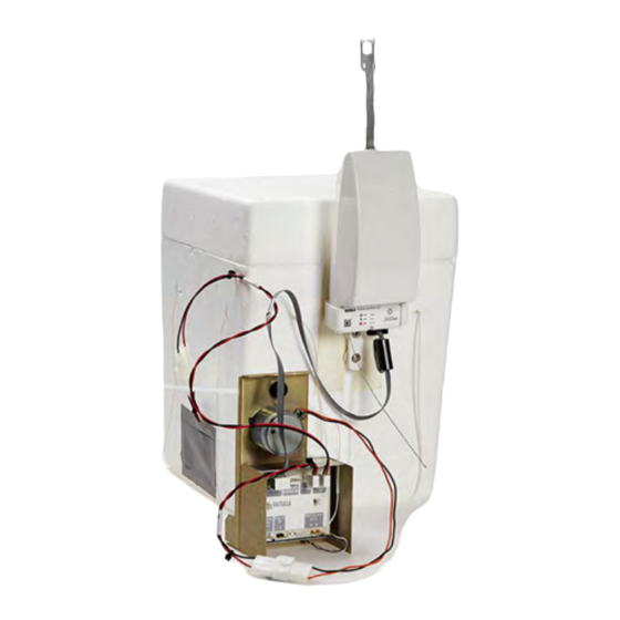
Page 75: Figure 45 Spc Ozone Sensor Inside The Flight Box
Air tube led through the groove For an example of the DMT sensor inside the flight box, see Figure 46 on page 74. Make sure that the wires and tubes are led through the grooves in the flight box VAISALA _______________________________________________________________________ 73... -
Page 76: Figure 46 Dmt Ozone Sensor Inside The Flight Box, Cover About
Figure 46 on page Flight box cover Ozone sensor placed inside the flight box Radiosonde RS41-SG Optionally, you can prepare the ozone sensor outside the flight box. The GAW report 201 recommends setting the ozone sensor into the flight box during the measuring of the background current prior to the flight, but, for practical reasons, you can also prepare the ozone sensor outside the flight box. -
Page 77: Figure 47 Air Outlet Hole And Air Intaketube Not Taped Over
Do not tape over the air outlet and air intake tube, as the measuring gas must be allowed to move in and out of the sensor box. See Figure 47 on page 75 for an illustration. Figure 47 Air Outlet Hole and Air IntakeTube Not Taped Over VAISALA _______________________________________________________________________ 75... -
Page 78: Figure 48 Supported Flight Box String In Dmt Ozone Sensor
Record I : ________µA NOTE The I value equals to Vaisala I , used in Vaisala scripts. NOTE Background current is measured after the flight box is closed: Close the cover of the flight box and tape the seam between the cover and the body of the box. -
Page 79: Figure 49 Entering Sensor Background Current In Mw41
The following information is displayed: Time: time in seconds Raw O3: ozone partial pressure Current Box temperature Ozone pump current 15. Turn off the pump and either take off the ozone destruction filter or shut off zero air flow. VAISALA _______________________________________________________________________ 77... -
Page 80: Constructing Sounding Accessories
Note that different installations are used depending on the components of the sounding. Always use an unwinder. An RSU stabilizer must be used if other than Vaisala-specific Totex parachute models are used. Before you begin, see the general instructions and various sounding accessories presented in Vaisala Guide to Sounding Preparations Technical Reference. -
Page 81: Figure 51 Assembly Of Rsu Stabilizer
Assemble the unwinder detainer to the radiosonde unwinder by pressing the detainer head into the radiosonde unwinder. Figure 52 Assembly of Detainer to Unwinder 1006-042 Continue sounding preparations by tying the flight box string to the unwinder stick. VAISALA _______________________________________________________________________ 79... -
Page 82: Activating Pump Motor Battery
User’s Guide ______________________________________________________________________ NOTE When DMT Model Z ozone sensor is used, the unwinder string is firmly attached to the ring hanger. If neither a parachute nor a radar reflector is used, connect the unwinder to the balloon as shown in Figure 53 on page 80. -
Page 83: Figure 54 Taped Flight Box
NOTE Do not tape over the battery compartment, as the fumes from the battery must be allowed to move out of the box. See Figure 54 on page for an example. Figure 54 Taped Flight Box 1403-174 VAISALA _______________________________________________________________________ 81... -
Page 84: Recording The Surface Ozone
User’s Guide ______________________________________________________________________ Recording the Surface Ozone NOTE The ASOPOS panel recommends the following: It is important that, before the launch, the ozone sensor has sampled surface air for at least 5 minutes; 10 minutes is recommended. In the MW41 Monitoring window, go to the Tabular data tab and select Raw ozone from the drop-down list. -
Page 85: Recording Post-Launch Data
You can also write down the information here: Launch time: = ________ hPa surf = ________ °C surf = ________ % RH surf Surface wind speed: ________m/s Wind direction: ________ Sky condition: _________________________________________ Other information: ______________________________________ VAISALA _______________________________________________________________________ 83... - Page 86 User’s Guide ______________________________________________________________________ 84 ___________________________________________________________________M211486EN-A...
-
Page 87: Chapter 3 Ozone Calculation
(P), temperature (T) and relative humidity (U) in the ground equipment. The measuring sample interval (measures each sensor once) of Radiosonde RS41-SG is 1 second. OIF411 is scanned in phase with the radiosonde PTU measuring sequence. Therefore, all the measured data is synchronized. -
Page 88: Ozone Partial Pressure Calculation
Therefore, different values for radiosondes with different sample rates must be used. A typical value for the window radius for RS41 is 4 (filtering window = 9 seconds). The median filtering algorithm is disabled by setting the window radius to 0. -
Page 89: Ozone Sensor Reactions
O -> 2 KOH + I Iodine, I , is formed and the I concentration of the solution starts to increase. If the external circuit is closed (switch S), reaction 1 is followed by reactions 2 and 3. VAISALA _______________________________________________________________________ 87... -
Page 90: Calculation Of Local Ozone Values
User’s Guide ______________________________________________________________________ In the cathode chamber: -> I + 2 e In the anode chamber: + 2 e -> 2 I These chemical reactions result in the following statement: ONE O MOLECULE CAUSES A CURRENT OF TWO ELECTRONS The current is measured with the OIF411 interface. NOTE The reaction occurs with all oxidants (such as NO ). - Page 91 NOTE used in this manual is equal to I used in the Vaisala scripts, and used in the GAW report 201, and the ASOPOS panel recommendations. VAISALA _______________________________________________________________________ 89...
-
Page 92: Background Current Correction (Ibg)
User’s Guide ______________________________________________________________________ NOTE Each ozone sensor manufacturer has their own recommendations for calculating I , Tp, and C . See Related Manuals on page Background Current Correction (I Background current correction (I ) is caused by oxidants other than ozone (mainly O ). -
Page 93: Pumping Time For 100 Ml Of Air (T)
The pumping time is measured during sounding preparations. The value is entered in the ground equipment during sounding preparations. Measured Airflow Temperature (T All sensors use measured values in a Vaisala application. Pump Efficiency Correction (Cef) The efficiency of the SPC Model 6A Ozonesonde air sampling pump decreases with altitude. -
Page 94: Table 13 Ozone Partial Pressure Correction Factors
User’s Guide ______________________________________________________________________ Table 13 Ozone Partial Pressure Correction Factors Ozone Partial Pressure Correction Factor C Atmospheric Sensor cathode solution volume Sensor cathode solution pressure hPa 2.5 cm volume 3.0 cm 1.160 1.171 1.124 1.131 1.087 1.092 10.0 1.054 1.055 20.0 1.033 1.032... -
Page 95: Additional Correction Factor (Cref)
= Total ozone from the sounding ': S = Residual total ozone In the software used in Vaisala equipment, the results of total ozone calculation are in Dobson Units (DU). For further information on total ozone calculation, see Chapter 3 Ozone... -
Page 96: Total Ozone From Sounding
User’s Guide ______________________________________________________________________ Total Ozone from Sounding The total ozone from the sounding is calculated by summing up the amount of ozone in the layers between two measurement points as expressed in the equation below. When using the units indicated in the list below, the equation gives the total ozone in units of grams per square meter (g/m §... -
Page 97: Residual Ozone (Total Ozone After Balloon Burst)
The total ozone can now be calculated from the equation: TOTALOZONE ': S ': R Another option is introduced in the GAW report 201. Post-calculation is possible, integrated ozone is reported, and residual can be calculated afterwards. It can also be changed in the script. VAISALA _______________________________________________________________________ 95... -
Page 98: Ozone In Μg/M³
User’s Guide ______________________________________________________________________ Ozone in µg/m³ Ozone density is, by definition: ------ where m = mass of ozone in volume V The ideal gas law is 3 × 3 × × where partial pressure of ozone in mPa mole number of ozone ideal gas constant temperature in K gives... -
Page 99: Accuracy Of Ozonesonde Measurement
Review Literature on page 119. NOTE The latest detailed technical data for the radiosonde and OIF411 can be found on the Vaisala website, www.vaisala.com. NOTE Detailed specifications for the ozone sensors are available directly from the manufacturers or from Vaisala. - Page 100 User’s Guide ______________________________________________________________________ 98 ___________________________________________________________________M211486EN-A...
-
Page 101: Ozone Interface Board Oif411 Data
OIF411, and how it is interpreted. Interpreting OIF411 Data Measurement Data When Radiosonde RS41 is connected to Ozone Interface Board OIF411, it sends the OIF411 measurement data through the additional sensor interface. The following information is contained: Instrument type and number... -
Page 102: Id Data
User’s Guide ______________________________________________________________________ xdata= <Instrument type is 05><Instrument number is 01><Ozone pump T [0.01 ºC]><Ozone current [0.0001uA]><Battery voltage [0.1V]> <Ozone pump current [1 mA]><Ext. voltage [0.1V]>CR This means that if OIF411 sends xdata=050108CA186A0750B637CR it is interpreted as shown in Table 15 on page 100: Table 15 OIF411 Data Interpretation 1... -
Page 103: Additional Data
For example: xdata=050108CA186A0750B637CRxdata=020300090009000900090 0090009CRxdata=10021FF44487A04E0410018FLFCR xdata=0304001000100010001000100010CR If additional sensor CFH is connected to OIF411, OIF411 sends data=050108CA186A0750B637CRxdata=10021DB6BC879 5200443018FLFCR where LF = line feed, CR = carriage return. VAISALA ______________________________________________________________________ 101... - Page 104 User’s Guide ______________________________________________________________________ 102 __________________________________________________________________M211486EN-A...
-
Page 105: Storage And Transportation
Ozone Interface Kit RSA411 must be stored and used properly in accordance with applicable instructions, User’s Guide, and specifications issued by Vaisala. Proper storage conditions must fulfill the following requirements: Ozone Interface Kit RSA411 must be stored in a dry, ventilated indoor storage space, and within the following key environmental limits (ref. -
Page 106: Transportation
User’s Guide ______________________________________________________________________ Transportation Ozone Interface Kit RSA411 must be transported in the original shipping package. The package is designed and built to survive and protect its contents in the environmental conditions described herein with the terminology and standards per standard: IEC 60721-3-2. Transportation of OIF411 requires climatic conditions 2K2 and mechanical conditions 2M1 of this standard: Transportation in weather-protected conditions. -
Page 107: Chapter 6 Technical Support
Read the radiosonde warranty information. Contact Vaisala technical support via e-mail or fax and request for RMA (Return Material Authorization) and shipping instructions. Proceed as instructed by Vaisala technical support and provide the failure report as requested. - Page 108 User’s Guide ______________________________________________________________________ 106 __________________________________________________________________M211486EN-A...
-
Page 109: Digicora Mw41 Ozone Data
You can use the report template editor in MW41 to create an ASCII output of the calculated ozone data. The data may also be programmatically accessed via the script interface during the sounding. The ozone-related data can be exported in the following files: VAISALA ______________________________________________________________________ 107... -
Page 110: Archived Ozone Data In Mw41
User’s Guide ______________________________________________________________________ calc_ozone.tsv and specsens.tsv. For information on creating a report in MW41, see the on-line help. Below is an example of an ozone data report output: Figure 57 Example of an MW41 Ozone Data Report Output Archived Ozone Data in MW41 The calculated ozone data is stored in XML format in a zipped .mwx sounding archive file. -
Page 111: Additional Sensor Data From Rs41
Appendix A _______________________________________________ DigiCORA MW41 Ozone Data Additional Sensor Data from RS41 Table 17 AdditionalSensorData Column Name Type Description SOUNDINGIDPK String Unique sounding ID RADIORXTIMEPK Double Radio time [s] INSTRUMENTTYPEPK String Instrument type identifier INSTRUMENTNUMBERPK String Instrument number MEASUREMENTOFFSET Double... -
Page 112: Calculated Ozone Data
User’s Guide ______________________________________________________________________ Calculated Ozone Data Ozone layer data with pressure correction is applied. Table 19 CalculatedOzone Column Name Type Description SOUNDINGIDPK String Unique sounding ID RADIORXTIMEPK Double Radio time [s] DATASRVTIME String Data server [yyyy-MM-dd HH:mm:ss.fff] PARTIALPRESSURE Double Calculated ozone partial pressure [mPa] BOXTEMPERATURE Double... -
Page 113: Table 20 Oif411Parameters/ Oif92Parameters
OIF92: Sensor thermistor resistance at 25 C temperature [Ohm] VREFCH3 Double OIF411: null OIF92: Reference value for voltage channel [V] VREFCH4 Double OIF411: null OIF92: Reference value for AUX channel [V] BGCURRENT Double Sensor background current [uA] VAISALA ______________________________________________________________________ 111... -
Page 114: Ozone Results
User’s Guide ______________________________________________________________________ Ozone Results Summary of calculated ozone data. Table 21 OzoneResults Column Name Type Description SOUNDINGIDPK String Unique sounding ID DATASRVTIME String Data server [yyyy-MM-dd HH:mm:ss.fff] INTEGRATEDOZONE Double Ozone accumulated up to the sounding termination [DU] (Dobson Unit) RESIDUALOZONE Double Estimated residual ozone... -
Page 115: Raw Ozone Data
[uA] BOXTEMPERATURE Double Sensor box temperature VOLTAGE Double OIF92: Channel 3 data OIF411: Battery voltage measurement [V] Double OIF411: ozone pump current value [mA] OIF92: channel 4 data EXTERNALVOLTAGE Double OIF411: external voltage measurement [V] OIF92: 0 VAISALA ______________________________________________________________________ 113... - Page 116 User’s Guide ______________________________________________________________________ 114 __________________________________________________________________M211486EN-A...
-
Page 117: Safety Instructions For Balloon Operators
Instead, release the defective balloon without load. It is not advisable to deflate the balloon, even outside the shed. Do not touch the balloon with bare hands except when holding it by the neck. Wear soft cotton gloves. VAISALA ______________________________________________________________________ 115... - Page 118 User’s Guide ______________________________________________________________________ Ensure that there are no pointed objects in the shed. Nails, hooks, hinges, padlocks, etc., are dangerous as they might scratch the inflated balloon. The balloon film is only 0.05 ... 0.1 mm thick upon launch; the slightest scratch could cause the balloon to burst prematurely.
-
Page 119: Checklist For Equipment And Supplies For Flight
Table 23 Checklist for Equipment Equipment Checked Ozone sensor with styrofoam flight box and motor battery Radiosonde RS41 Ozone Interface Board OIF411 Balloon (plastic or rubber) 5 meters of string (strength about 300 to 500 N), an unwinder and a detainer... - Page 120 User’s Guide ______________________________________________________________________ Table 23 Checklist for Equipment (Continued) Equipment Checked Syringe, 3 ml volume (equipped with Teflon tube), for use with the sensor cathode solution Syringe, 3 ml volume, for use with the sensor anode solution Roll of firm tape, 2 inches (5 cm) wide Apparatus for measuring ozone sensor air flow rate Ozonesonde power supply for pump motor rated at 12 to 13 VDC, 300 mA...
-
Page 121: Performance Review Literature
The Balloon Experiment on Standards for Thompson, J. Witte, F.J. Schmidlin, Ozonesondes, J. Geophys. Res., 113, D04307, doi: 10.1029/ G. Brothers, T. Sasaki 2007JD008975. Komhyr, W. D. (1969), Electrochemical concentration cells for gas analysis, Ann. Geoph., 25, 203 - 210. 2008. VAISALA ______________________________________________________________________ 119... - Page 122 User’s Guide ______________________________________________________________________ Table 24 Performance Review Literature (Continued) Name Details Godson, W.L. The representation and analysis of vertical distributions of ozone, Quarterly Journal of the Meteorological Society, Vol. 88, No. 377, July 1962. Hoegger, B.A. & all Contribution of Switzerland to International Ozonesonde Intercomparisons.
- Page 123 J. Geophys. Res., 113, D13302, doi:10.1029/2007JD009091. 2008. Third WMO intercomparison of the ozonesondes used by the Global ozone observing System, Vanscoy Canada 13-24 May 1991, WMO/ Global Atmosphere Watch/WMO Global Ozone Research and Monitoring Project, Report No 27. VAISALA ______________________________________________________________________ 121...
- Page 124 *M211486EN*...
Need help?
Do you have a question about the RS41 and is the answer not in the manual?
Questions and answers