Sign In
Upload
Manuals
Brands
Vaisala Manuals
Measuring Instruments
RS41
Vaisala RS41 Manuals
Manuals and User Guides for Vaisala RS41. We have
2
Vaisala RS41 manuals available for free PDF download: User Manual
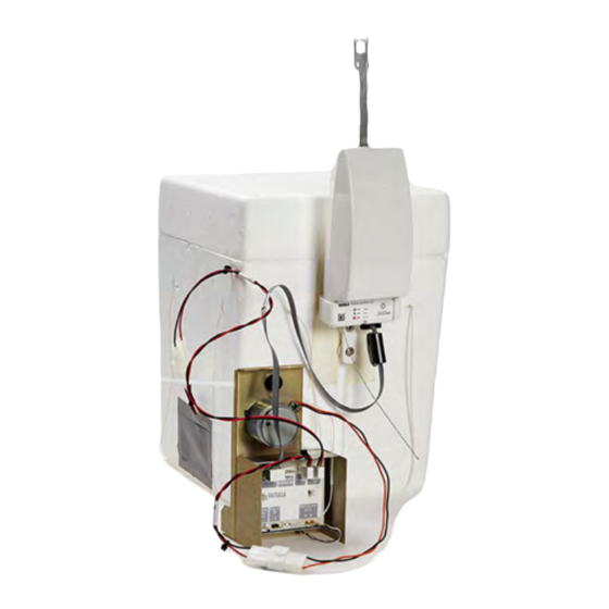
Vaisala RS41 User Manual (124 pages)
Ozone Sounding with Radiosonde
Brand:
Vaisala
| Category:
Measuring Instruments
| Size: 2.23 MB
Table of Contents
Table of Contents
3
Chapter 1 General Information
11
About this Manual
11
Version Information
13
Related Manuals
13
Documentation Conventions
13
Table 1 Manual Revisions
13
Table 2 Related Manuals
13
Product-Related Safety Precautions
14
Lithium Battery-Related Precautions
15
Transporting RS41 Radiosondes with Lithium Batteries
15
Figure 1 Lithium Battery Handling Label
16
ESD Protection
17
Recycling
17
Trademarks
17
Product Returns
18
Chapter 2 Product and System Component Overview
19
Introduction to Ozone Sounding
19
Ozone Sensor Unit
20
Figure 2 SPC ECC-6A Ozone Sensor Parts
21
Ozone Interface Kit RSA411
22
Figure 3 RSA411 Ozone Interface Kit Contents
22
Figure 4 Ozone Sensor Interface Board OIF411
23
Ozone Interface Board OIF411
23
Figure 5 OIF411 Terminals Marked on Sticker
24
Table 3 OIF411 Terminals
24
Figure 6 OIF411 Dimensions
25
Radiosonde RS41 Additional Sensor Interface
26
Figure 7 RS41 Additional Sensor Interface
26
Table 4 Electrical Interface of RS41 and the Additional Sensor
26
Equipment and Material Needed
27
Vaisala Ozone Sounding Startup Kit
28
Table 5 Ozone Sounding Startup Kit
28
Figure 8 Ozonizer/Test Unit TSC-1
29
Ozonizer/Test Unit TSC-1
29
Figure 10 EC White Bench O3S Tester Made by Droplet Measurement Technologies
31
Figure 9 EC Black Bench O3S Tester Made by EC
31
Ozone Destruction Filter
32
Table 6 Equipment Required for Ozone Destruction Filter
32
Figure 11 Ozone Destruction Filter
33
Pump Test Unit
33
Table 7 Equipment Required for Pump Test Unit
33
Figure 12 Vacuum/Pressure Gauge
34
Laboratory Ware Set
35
Ozone Chemicals
36
Table 8 Laboratory Ware Needed
36
Table 9 Required Ozone Chemicals
36
Air Flow Meter
37
Using the Air Flow Meter
37
Table 10 Equipment Required for Air Flow Meter
37
Figure 13 Air Flow Rate Measurement
39
Other Equipment and Material
40
Balance
40
Thermometer
40
Power Supply
40
Protective Gloves
40
Expendables and Spare Parts
41
Constructing an Ozone Sounding
43
Sounding Preparation Phases and Schedule
43
Preparations 7 to 3 Days Prior to Release
45
Preparation Steps
45
Preparations on the Day of Release
48
Preparation Steps
48
Preparations Just before Release (2 - 0 Hours)
50
Starting Preparations
51
Attaching Radiosonde Holder to Flight Box
51
Figure 14 Radiosonde Holder Attachment
52
Figure 15 Radiosonde Holder Measurements (A) and Position (B)
53
Figure 16 Marking the Positions of the Holder Screws
54
Attaching OIF411 to Spc's Ozone Sensor Frame
55
Figure 17 Inserting the Dowels
55
Figure 18 Attaching OIF411 to Ozone Sensor
56
Figure 19 Wing Nuts on the Back of OIF411
57
Figure 20 OIF411 Being Attached to the Ozone Sensor Frame
57
Attaching OIF411 to Dmt's Ozone Sensor Frame
58
Figure 21 OIF411 Wing Nuts Tightened
58
Figure 22 Droplet Measurements Model Z Sensor
59
Figure 23 Drilling the Ozone Sensor Frame Holes
59
Connecting Ozone Sensor Wires to OIF411
60
Figure 24 Ozone Sensor Attached to the DMT Frame with M3 Nuts
60
Figure 25 OIF411 Terminals Marked on Sticker
61
Table 12 OIF411 Terminals
61
Figure 26 Connecting Sensor Wires to OIF411
62
Preparing the Radiosonde and OIF411
63
Connecting Ozone Sensor Pump to OIF411
63
Figure 27 Connecting Ozone Sensor Pump Cable
63
Connecting Ozone Pump Battery to OIF411
64
Figure 28 Connecting Ozone Sensor Battery Cable
64
Connecting Thermistor Cable to Ozone Sensor
65
Pump
65
Figure 29 SPC ECC-6A with Thermistor Assembled
65
Figure 30 DMT Model Z with OIF411 Temperature Sensor
65
Connecting Additional Sensor Cable to OIF411
66
Connecting Heating Battery to OIF411 (Optional)
66
Figure 31 Connecting Heating Battery
66
Figure 32 Two-Sided Tape Attached to the Battery
67
Figure 33 Battery Wires Running between the Ozone Sensor
67
Preparing the Radiosonde with Ground Equipment
68
Figure 34 Ozone Sensor Information
69
Figure 35 Radiosonde Preparation in Progress
69
Figure 36 Waiting for Background Current
70
Figure 37 Do Not Touch the Radiosonde Sensors
70
Figure 38 Connecting Radiosonde Cable
71
Figure 39 Checking Radiosonde Interface Connector
71
Figure 40 OIF411 Connected to Radiosonde Interface Connector
72
Figure 41 Do Not Touch the Radiosonde Sensors
72
Figure 42 Attaching Radiosonde to the Holder
73
Figure 43 Pushing the Holder into Place
74
Figure 44 Radiosonde RS41 Attached to the Holder
74
Figure 45 SPC Ozone Sensor Inside the Flight Box
75
Figure 46 DMT Ozone Sensor Inside the Flight Box, Cover about
76
Figure 47 Air Outlet Hole and Air Intaketube Not Taped over
77
Figure 48 Supported Flight Box String in DMT Ozone Sensor
78
Figure 49 Entering Sensor Background Current in MW41
79
Figure 50 Viewing Raw Ozone Data in MW41
79
Constructing Sounding Accessories
80
Figure 51 Assembly of RSU Stabilizer
81
Figure 52 Assembly of Detainer to Unwinder
81
Activating Pump Motor Battery
82
Figure 53 Unwinder Attached to the Balloon Neck
82
Figure 54 Taped Flight Box
83
Recording the Surface Ozone
84
Launching the Balloon
84
Figure 55 Viewing Raw Ozone Data in MW41
84
Recording Post-Launch Data
85
Chapter 3 Ozone Calculation
87
Averaging and Eliminating Irrelevant Measuring
87
Results
87
Ozone Partial Pressure Calculation
88
Ozone Sensor Operating Principle
88
Ozone Sensor Reactions
89
Figure 56 Electrochemical Cell Construction
89
Calculation of Local Ozone Values
90
Background Current Correction (IBG)
92
Pumping Time for 100 Ml of Air (T)
93
Measured Airflow Temperature (TP)
93
Pump Efficiency Correction (Cef)
93
Table 13 Ozone Partial Pressure Correction Factors
94
Table 14 Ozone Partial Pressure Correction Factors
94
Additional Correction Factor (Cref)
95
Total Ozone Calculation
95
Total Ozone from Sounding
96
Residual Ozone (Total Ozone after Balloon Burst)
97
Ozone in Μg/M³
98
Accuracy of Ozonesonde Measurement
99
Chapter 4 Ozone Interface Board Oif411 Data
101
Interpreting OIF411 Data
101
Measurement Data
101
ID Data
102
Table 15 OIF411 Data Interpretation 1
102
Additional Data
103
Table 16 OIF411 Data Interpretation 2
103
Chapter 5 Storage and Transportation
105
Storage
105
Transportation
106
Chapter 6 Technical Support
107
Product Returns
107
Technical Support
107
Appendix A Digicora Mw41 Ozone Data
109
Calculating Ozone Data in MW41
109
Reporting Ozone Data in MW41
109
Archived Ozone Data in MW41
110
Figure 57 Example of an MW41 Ozone Data Report Output
110
Additional Sensor Data from RS41
111
Additional Sensor Data from RS92
111
Table 17 Additionalsensordata
111
Table 18 Rs92Specialsensordata
111
Calculated Ozone Data
112
OIF411 or OIF92 Ozone Parameters
112
Table 19 Calculatedozone
112
Table 20 Oif411Parameters/ Oif92Parameters
113
Ozone Results
114
Table 21 Ozoneresults
114
Raw Ozone Data
115
Table 22 Rawozone
115
Appendix B
117
Safety Instructions for Balloon Operators
117
Appendix C
119
Checklist for Equipment and Supplies for Flight
119
Preparations
119
Table 23 Checklist for Equipment
119
Appendix D
121
Performance Review Literature
121
Table 24 Performance Review Literature
121
Advertisement
Vaisala RS41 User Manual (104 pages)
Ozone Sounding with Vaisala Radiosonde
Brand:
Vaisala
| Category:
Accessories
| Size: 2.18 MB
Table of Contents
Table of Contents
3
About this Document
9
General Information
9
Version Information
9
Related Manuals
9
Table 2 Related Manuals
9
Documentation Conventions
10
Trademarks
10
Product-Related Safety Precautions
10
Lithium Battery-Related Precautions
12
Transporting RS41 Radiosondes with Lithium Batteries
12
Transporting Ozone Sensors with Lithium Batteries
13
ESD Protection
14
Product and System Component Overview
15
Introduction to Ozone Sounding with RS41
15
Ozone Sensor Unit
15
Figure 2 SPC ECC-6A Ozone Sensor Parts
16
Ozone Interface Kit RSA411
17
Figure 3 ECC-6A and Model Z Cathode and Anode
17
Figure 4 RSA411 Ozone Interface Kit Contents
17
Figure 5 Ozone Sensor Interface Board OIF411
18
Figure 6 OIF411 Terminals Marked on Sticker
19
Table 3 OIF411 Terminals
19
Figure 7 OIF411 Dimensions
20
Radiosonde RS41 Additional Sensor Interface
21
Equipment and Material Needed
21
Figure 8 RS41 Additional Sensor Interface
21
Table 4 Electrical Interface of RS41 and the Additional Sensor
21
Vaisala Ozone Sounding Startup Kit
22
Table 5 Ozone Sounding Startup Kit
22
Ozonizer / Test Unit KTU-3
23
Ozonizer/Test Unit TSC-1
23
Figure 9 EN-SCI Ozonizer /Test Unit KTU-3
23
Figure 10 Ozonizer/Test Unit TSC-1
24
Ozone Destruction Filter
25
Figure 11 EC Black Bench O3S Tester Made by EC
25
Table 6 Equipment Required for Ozone Destruction Filter
25
Pump Test Unit
26
Figure 1 Lithium Battery Handling Label
26
Figure 12 Ozone Destruction Filter
26
Table 7 Equipment Required for Pump Test Unit
26
Laboratory Ware Set
27
Figure 13 Vacuum/Pressure Gauge
27
Table 8 Laboratory Ware Needed
27
Ozone Chemicals
28
Air Flow Meter
28
Table 9 Required Ozone Chemicals
28
Other Equipment and Material
29
Table 10 Equipment Required for Air Flow Meter
29
Expendables and Spare Parts
30
Constructing an Ozone Sounding
31
Sounding Preparation Phases and Schedule
31
Preparing the Cathode and Anode Solutions
32
Preparations 7 to 3 Days Prior to Release
32
Using the Air Flow Meter
33
Preparation Steps 7 to 3 Days Prior to Release
34
Figure 14 Air Flow Rate Measurement
34
Table 11 Values in Ozonizer
35
Preparation Steps on the Day of Release
36
Preparations Just before Release (2 - 0 Hours)
37
Table
37
Starting Preparations
38
Table 12 Workflow for Ozone Sounding Preparations 45 Minutes
38
Attaching Radiosonde Holder to Flight Box
39
Figure 15 Radiosonde Holder Attachment
39
Figure 16 Radiosonde Holder Measurements (A) and Position (B)
40
Figure 17 Marking the Positions of the Holder Screws
41
Attaching OIF411 to Spc's Ozone Sensor Frame
42
Figure 18 Inserting the Dowels
42
Figure 19 Attaching OIF411 to Ozone Sensor
43
Figure 20 Wing Nuts on the Back of OIF411
44
Figure 21 OIF411 Being Attached to the Ozone Sensor Frame
44
Attaching OIF411 to EN-SCI Ozone Sensor Frame
45
Figure 22 OIF411 Wing Nuts Tightened
45
Figure 23 EN-SCI Model Z Sensor
46
Connecting Ozone Sensor Wires to OIF411
47
Figure 24 Drilling the Ozone Sensor Frame Holes
47
Figure 25 Ozone Sensor Attached to the Model Z Frame with M3 Nuts
47
Figure 26 OIF411 Terminals Marked on Sticker
48
Table 13 OIF411 Terminals
48
Preparing the Radiosonde and OIF411
49
Figure 27 Connecting Sensor Wires to OIF411
49
Figure 28 Connecting Ozone Sensor Pump Cable
50
Figure 29 Connecting Ozone Sensor Battery Cable
50
Figure 30 SPC ECC-6A with Thermistor Assembled
51
Figure 31 EN-SCI Model Z with OIF411 Temperature Sensor Assembled
51
Figure 32 Connecting Heating Battery
52
Figure 33 Two-Sided Tape Attached to the Battery
53
Figure 34 Battery Wires Running between the Ozone Sensor Frame Wall and the Ozone Sensor
53
Preparing the Radiosonde with Ground Equipment
54
Figure 35 Ozone Sensor Information
55
Figure 36 Radiosonde Preparation in Progress
55
Figure 37 Waiting for Background Current
56
Figure 38 Connecting Radiosonde Cable
57
Figure 39 Bending and Removing Piece of EPS Cover
57
Figure 40 Checking Radiosonde Interface Connector
58
Figure 41 OIF411 Connected to Radiosonde Interface Connector
58
Figure 42 Attaching Radiosonde to the Holder
59
Figure 43 Pushing the Holder into Place
60
Figure 44 Radiosonde RS41 Attached to the Holder
60
Figure 45 SPC Ozone Sensor Inside the Flight Box
61
Figure 46 EN-SCI Ozone Sensor Inside the Flight Box, Cover about to be Closed
62
Figure 47 Air Outlet Hole and Air Intaketube Not Taped over
63
Figure 48 Supported Flight Box String in EN-SCI Ozone Sensor Flight Box
64
Constructing Sounding Accessories
65
Figure 49 Entering Sensor Background Current in MW41
65
Figure 50 Viewing Raw Ozone Data in MW41
65
Figure 51 Securing Unwinder with String (on the Left) or Tape (on the Right)
66
Pump Motor Battery
67
Figure 52 RSU Stabilizer Attached to the Unwinder
67
Figure 53 Battery Holder with Lithium Batteries, Wires, and Connector
68
Figure 54 Batteries Inserted in the Ozone Sensor Styrofoam Box
68
Recording the Surface Ozone
69
Figure 55 Taped Flight Box, Battery Connectors in Front
69
Launching the Balloon
70
Recording Post-Launch Data
70
Figure 56 Viewing Raw Ozone Data in MW41
70
Ozone Calculation
71
Ozone Calculation Overview
71
Averaging and Eliminating Irrelevant Measuring Results
71
Ozone Partial Pressure Calculation
72
Ozone Sensor Operating Principle
72
Figure 57 Electrochemical Cell Construction
72
Ozone Sensor Reactions
73
Calculation of Local Ozone Values
73
Table 14 Ozone Partial Pressure Correction Factors
76
Table 15 Ozone Partial Pressure Correction Factors
76
Total Ozone Calculation
77
Table 16 Total Ozone Calculation
77
Total Ozone from Sounding
78
Table 17 Total Ozone from Sounding
78
Residual Ozone (Total Ozone after Balloon Burst)
79
Ozone in Μg/M³
79
Accuracy of Ozonesonde Measurement
81
Ozone Interface Board OIF411 Data Interpretation
83
Measurement Data
83
ID Data
83
Table 18 OIF411 Data Interpretation 1
83
Additional Data
84
Table 19 OIF411 Data Interpretation 2
84
Storage and Transportation
85
Storage
85
Transportation
85
Appendix A: Digicora MW41 Ozone Data
87
Calculating Ozone Data in MW41
87
Reporting Ozone Data in MW41
87
Archived Ozone Data in MW41
87
Figure 58 Example of an MW41 Ozone Data Report Output
87
Additional Sensor Data from RS41
88
Additional Sensor Data from RS92
88
Calculated Ozone Data
88
Table 20 Additionalsensordata
88
Table 21 Rs92Specialsensordata
88
Table 22 Calculatedozone
88
OIF411 or OIF92 Ozone Parameters
89
Table 23 Oif411Parameters / Oif92Parameters
89
Ozone Results
90
Table 24 Ozoneresults
90
Raw Ozone Data
91
Table 25 Rawozone
91
Appendix B: Safety Instructions for Balloon Operators
93
Appendix C: Checklist for Equipment and Supplies for Flight Preparations
95
Table 26 Checklist for Equipment
95
Appendix D: Performance Review Literature
97
Table 27 Performance Review Literature
97
Technical Support
101
Recycling
101
Advertisement
Related Products
Vaisala RT20A
Vaisala Radiosonde RS41-SGM
Vaisala Radiosonde RS41-D
Vaisala RS92-D
Vaisala Radiosonde RS92-SGP
Vaisala RS41-SG
Vaisala RS41-SGP
Vaisala RVP900
Vaisala RME111
Vaisala RB31
Vaisala Categories
Transmitter
Measuring Instruments
Accessories
Weather Station
Test Equipment
More Vaisala Manuals
Login
Sign In
OR
Sign in with Facebook
Sign in with Google
Upload manual
Upload from disk
Upload from URL