Table of Contents
Advertisement
Quick Links
Advertisement
Table of Contents

Subscribe to Our Youtube Channel
Related Manuals for Raytech WR14


Summary of Contents for Raytech WR14
- Page 1 VERSION 3.03 INSTRUCTION MANUAL MODEL: WR14 & WR50-12/13 WINDING RESISTANCE METERS WR50-12/13: 50A W WR14: 15A W INDING ESISTANCE ETER INDING ESISTANCE ETER RAYTECH USA, INC. 118 SOUTH 2ND STREET, PERKASIE, PA 18944 USA T: 267 404 2676 | F: 267 404 2685 | WWW.RAYTECHUSA.COM...
-
Page 2: Table Of Contents
Display With Touch Panel ........................20 Potential Receptacle ..........................20 Current Receptacle ..........................20 External ..............................20 Ground Terminal ..........................20 Temperature Receptacle ........................20 Interface ............................... 20 WR14 Front Panel overview ........................21 WR14 / WR50-12/13 Winding Resistance Meter Instruction Manual Version 3.03... - Page 3 Cable Extensions for WR100R ........................ 75 10M Cable Extension Set for the WR100-12R ..................75 10M Cable Extension Set for the WR100-13R ..................76 Cable Extensions for WR50R ........................77 Version 3.03 WR14 / WR50-12/13 Winding Resistance Meter Instruction Manual...
- Page 4 10M Cable Extension Set for the WR50-12R ..................77 10M Cable Extension Set for the WR50-13R ..................78 10M Cable Extension Set for the WR14-R ..................79 Technical Specifications ..........................80 WR50 ............................... 80 WR14 ............................... 82 Interfaces..............................84 Hardware ..............................84 RS 232 ..............................
- Page 5 Parameters for Demagnetizing ......................110 Multiplexer ..............................111 Error Messages ............................112 Trouble Shooting ............................114 Warranty Conditions ..........................116 Limitation of Warranty ..........................117 Arbitration .............................. 117 Contact Information: ..........................118 Version 3.03 WR14 / WR50-12/13 Winding Resistance Meter Instruction Manual...
-
Page 6: Safety Precautions
Failure to comply with these precautions and other specific warnings violates safety standards of design, manufacture, and intended use. Raytech and its affiliates assume no liability for the operation and use of this equipment. -
Page 7: Unpacking
(WR50-13 only) USB Memory Stick Instruction Manual If any of the above items are missing or damaged, contact your local representative or Raytech USA immediately. Optional test leads may be ordered (other than shown). Version 3.03 WR14 / WR50-12/13 Winding Resistance Meter Instruction Manual... - Page 8 USB Memory Stick Instruction Manual If any of the above items are missing or damaged, contact your local representative or Raytech USA immediately. Optional test leads may be ordered (other than shown). WR14 / WR50-12/13 Winding Resistance Meter Instruction Manual...
-
Page 9: Wr14
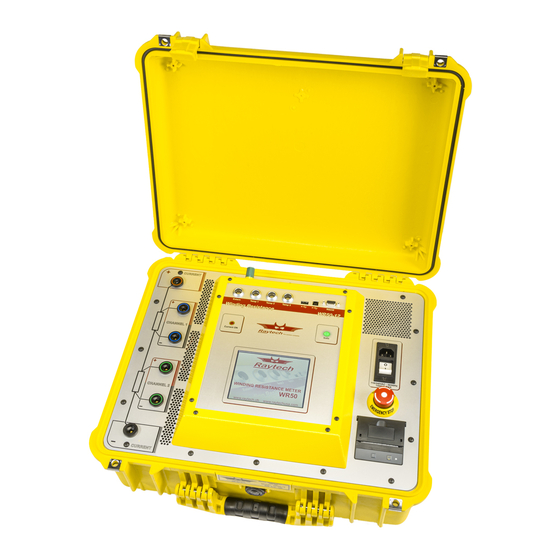
The results are reported on the easy-to-read, color LCD display and can be stored or printed. Compact Design: The WR50 and the WR14 series of instruments are available in their own rugged waterproof field cases. -
Page 10: Advantages & Features
In general, there are no limitations on testing low or high inductive windings of transformers. The test systems are specially designed to test all transformer windings. The WR14 is battery operated in addition to mains power. WR14 / WR50-12/13 Winding Resistance Meter Instruction Manual... -
Page 11: Discharging The Transformer Windings
The internal discharge circuit dissipates the stored energy in the transformer windings with a “Constant Power Discharge Circuit” that is unique to all transformer winding test systems. That is the reason why Raytech systems can discharge transformers more than 10 times faster than any other system on the market. -
Page 12: Quick Start Guide
Wait until the green light shows “Safe” before handling the cables. For examples of transformer connections, see the next pages. The checkbox for “Use Profiles” is not selected in the Setup under General. WR14 / WR50-12/13 Winding Resistance Meter Instruction Manual Version 3.03... -
Page 13: Instrument Operation - Using Profiles
1. Power on the instrument. Press Setup. 3. Touch “Profile.” 4. Touch “New.” 5. Touch “New Transformer.” 6. Define new Transformer parameters by selecting the symbols at the bottom of the screen, then touch “Go.” Version 3.03 WR14 / WR50-12/13 Winding Resistance Meter Instruction Manual... - Page 14 9. Choose a Caption. 11. Start a measurement as usual. WARNING! Wait until the green light shows “Safe” before handling the cables. For examples of transformer connections, see the next pages. WR14 / WR50-12/13 Winding Resistance Meter Instruction Manual Version 3.03...
-
Page 15: Selection Of The Proper Current Range
This helps to stabilize the measurement and saves time. The potential leads must be connected in between the current leads. Do not clip the potential leads to the current leads. Version 3.03 WR14 / WR50-12/13 Winding Resistance Meter Instruction Manual... -
Page 16: Single Phase Transformer, Vector Group 0
SINGLE PHASE TRANSFORMER, VECTOR GROUP 0 Measurement of HV and LV Winding WR14 / WR50-12/13 Winding Resistance Meter Instruction Manual Version 3.03... -
Page 17: Three Phase Transformer, Δ - Δ Vector Group 0
THREE PHASE TRANSFORMER, Δ – Δ VECTOR GROUP 0 Measurement of HV and LV Winding Version 3.03 WR14 / WR50-12/13 Winding Resistance Meter Instruction Manual... -
Page 18: Three Phase Transformer Δ - Y, One Lv Winding
THREE PHASE TRANSFORMER Δ – Y, ONE LV WINDING Measurement of one LV Winding WR14 / WR50-12/13 Winding Resistance Meter Instruction Manual Version 3.03... -
Page 19: Three Phase Transformer Δ - Y, Two Lv Winding
THREE PHASE TRANSFORMER Δ – Y, TWO LV WINDING Measurement of two LV Winding Version 3.03 WR14 / WR50-12/13 Winding Resistance Meter Instruction Manual... -
Page 20: Operation Elements For Field Units
Therefore, there are no ink cartridges required or printer heads. Special thermal paper is required for the printer to operate properly. This illustrates a WR50-12 (2 channel instrument), the WR50-13 has a 3 channel. WR14 / WR50-12/13 Winding Resistance Meter Instruction Manual Version 3.03... -
Page 21: Safety Indicator
These three (3) receptacles are for the external temperature probes (Optional accessory part number: 2021N-26001). INTERFACE RS 232 and USB 2.0 (1 Host, 1 Device). See “Interfaces” on page 84 for more details. Version 3.03 WR14 / WR50-12/13 Winding Resistance Meter Instruction Manual... -
Page 22: Wr14 Front Panel Overview
CHARGE INDICATOR AND MAIN SWITCH This LED light will blink when charging the battery, even when the WR14 is powered off. When the instrument is powered on, the LED light will remain constant and will blink if a power cord is attached and charging the internal battery. -
Page 23: Ground Terminal
The device will remain in a safe mode state. MAINS INPUT Connect a power cord to the Mains Input (88 to 264 V / 47 to 63 Hz). Version 3.03 WR14 / WR50-12/13 Winding Resistance Meter Instruction Manual... -
Page 24: Operating Menu
“Results” button appears on the main measurement screen as shown below. This is an indication that the Standard mode is selected. For more details, see “Menu Structure Without Using Profiles” on page 25. WR14 / WR50-12/13 Winding Resistance Meter Instruction Manual Version 3.03... - Page 25 Profiles mode is for assigning the results to a transformer Profile. When Profiles mode is selected, the main measurement screen will display "Profile" in the lower right of the main screen instead of "Results." For more details, see “Menu Structure Using Profiles” on page 26. Version 3.03 WR14 / WR50-12/13 Winding Resistance Meter Instruction Manual...
-
Page 26: Menu Structure Without Using Profiles
To work without using the Profiles mode, turn off the Profiles mode in the Setup menu by unchecking the check box shown in “Operating Menu” on page 23. The results will be simply organized and saved by date and time without any transformer information (Standard mode). WR14 / WR50-12/13 Winding Resistance Meter Instruction Manual Version 3.03... -
Page 27: Menu Structure Using Profiles
*Only available if a USB Key is connected to the instrument. To use the Profiles mode, as described in this chapter, turn it on in the Setup menu by selecting the check box shown in “Operating Menu” on page 24. Version 3.03 WR14 / WR50-12/13 Winding Resistance Meter Instruction Manual... -
Page 28: Introduction To Transformer Profiles And Data Structure
Or you may load an existing transformer Profile then do the required measurements and store them. In this case, the new measurement will be attached (stored) with the loaded or active transformer Profile. This is illustrated in the following scenario: WR14 / WR50-12/13 Winding Resistance Meter Instruction Manual Version 3.03... - Page 29 In the example above, it is the 1st of September. The transformer Profile is loaded (made active) and a measurement is done. The new measurement data was saved and stored (linked) with the transformer Profile. Thus creating a history for this particular transformer. Version 3.03 WR14 / WR50-12/13 Winding Resistance Meter Instruction Manual...
-
Page 30: Main Menu
If you don't use Profiles, you will have the Result Button. See page 52. If you have not selected “Use Profiles” in the Setup Menu, you will see “Results” instead of the “Profile” button. WR14 / WR50-12/13 Winding Resistance Meter Instruction Manual Version 3.03... - Page 31 Status Shows the measurement parameters. Temp. Correction Shows the temperature parameters. Temperature variables can be modified by pressing the Setup Button or directly in the text (--.-°C). See page 49. Version 3.03 WR14 / WR50-12/13 Winding Resistance Meter Instruction Manual...
-
Page 32: Start
Press Stop. Instrument stops the measurement and begins the discharge process. DO NOT disconnect the measuring cables until the green light is on and the indication for Safe mode appears. WR14 / WR50-12/13 Winding Resistance Meter Instruction Manual Version 3.03... -
Page 33: Demag
Select the demagnetizing current, which is usually the same current as the test current, and then press start. The Demagnetizing procedure runs automatically. For a technical description of the demagnetizing feature, see “Demagnetizing” on page 109. Version 3.03 WR14 / WR50-12/13 Winding Resistance Meter Instruction Manual... -
Page 34: Setup
This screen allows the selection and setting of the measurement mode (single, continuous or interval). Range This screen allows the selection, modification and setting of the range for the Test Current. Temp. Corr. This screen activates the temperature correction feature. WR14 / WR50-12/13 Winding Resistance Meter Instruction Manual Version 3.03... - Page 35 Use Profiles This allows operation of, or access to, transformer profiles. For more information see “Menu Structure Using Profiles” on page 26 or “Menu Structure Without Using Profiles” on page 25. Version 3.03 WR14 / WR50-12/13 Winding Resistance Meter Instruction Manual...
- Page 36 Select the corresponding color button to change the color: Palette: Choose a color by selecting a predefined color available. User Defined Colors: Choose a color by manually adjusting the color select bar. WR14 / WR50-12/13 Winding Resistance Meter Instruction Manual Version 3.03...
- Page 37 Ohm/Length. The test results are then corrected to the selected display method. The length of the test object is predefined by the customer. Enter the length of the test specimen. Version 3.03 WR14 / WR50-12/13 Winding Resistance Meter Instruction Manual...
- Page 38 If there is no valid license status displayed, contact your local representative or Raytech. To modify or extend the license, enter a new license code. The license code is generated by Raytech. WR14 / WR50-12/13 Winding Resistance Meter Instruction Manual Version 3.03...
- Page 39 The system will detect and automatically install the new firmware and restart the system. Language The selection of language for the operating menu can be made. Restart the instrument to activate the desired language selected. Version 3.03 WR14 / WR50-12/13 Winding Resistance Meter Instruction Manual...
- Page 40 Select the date by pressing on the actual day. Time Select hour/minute/second by highlighting the numbers in the clock. Pressing the arrows will increase or decrease the time settings. WR14 / WR50-12/13 Winding Resistance Meter Instruction Manual Version 3.03...
- Page 41 Certain external USB Printers can be connected. Select the desired printer to print results. Printers not listed are not supported. For more information, see “USB Printer Info” on page 103. Version 3.03 WR14 / WR50-12/13 Winding Resistance Meter Instruction Manual...
- Page 42 USB-driver and so on. For more information see “Service Mode” on page 97. The Service Mode has a limited access. Enter the corresponding code or exit directly by pressing “#.” WR14 / WR50-12/13 Winding Resistance Meter Instruction Manual Version 3.03...
- Page 43 In the tab Config, you can change the name (Caption) of the measurement channels. Click on the white field to change the name (Caption) of the measurement channels. Enter a name. Do not select “Use Profiles” in the Setup under “General.” Version 3.03 WR14 / WR50-12/13 Winding Resistance Meter Instruction Manual...
- Page 44 This feature is very useful if utilizing a Raytech multiplexer which will automatically set the appropriate relay. Thus, with a multiplexer, you connect the measurement cables to a Transformer only once and all measurements are completed without changing any cables.
- Page 45 Tap: If the transformer has Taps, select the Tap to be measured. Version 3.03 WR14 / WR50-12/13 Winding Resistance Meter Instruction Manual...
- Page 46 If the result is out of the selected parameters, a red light in the main screen will illuminate and indicate this condition. If the selected conditions are almost met, a yellow light in the main screen will illuminate. WR14 / WR50-12/13 Winding Resistance Meter Instruction Manual Version 3.03...
- Page 47 27, 30, 40, 50...seconds. Note: The current remains ON for the duration of the test and automatically stops after the “Count” number of measurements are taken. Version 3.03 WR14 / WR50-12/13 Winding Resistance Meter Instruction Manual...
- Page 48 If this feature is selected, the instrument will also output to a connected printer when the measurements are stored. AutoSave USB: The results will also be stored on a USB Key, if connected to the instrument during a measurement. Not available in the WR14. WR14 / WR50-12/13 Winding Resistance Meter Instruction Manual Version 3.03...
- Page 49 Adjust all 3 settings by moving the cursor left or right to the desired Current level. Press OK when finished. The maximum current of the WR50 is 50A. The maximum current of the WR14 is 15A. Version 3.03 WR14 / WR50-12/13 Winding Resistance Meter Instruction Manual...
- Page 50 If a temperature probe (optional accessory part number: 2021N-26001) is not available, activate the “Ext” box and fill in the temperature of the test object that was measured with an external temperature meter. WR14 / WR50-12/13 Winding Resistance Meter Instruction Manual Version 3.03...
- Page 51 The “T” in the measuring channel box shows that the displayed resistance value is corrected. In this example it is corrected to 25 °C using Tk of Copper and referring to Temperature probe 1. Version 3.03 WR14 / WR50-12/13 Winding Resistance Meter Instruction Manual...
- Page 52 If the display shows a crossed Red T, the result is not corrected because a temperature probe is missing or not recognized by the system. WR14 / WR50-12/13 Winding Resistance Meter Instruction Manual Version 3.03...
-
Page 53: Results
Shows the overview of the measurements which are sorted by Date/Time. You can select multiple results. See “Operating Menu” on page 23 for instructions regarding how you can select it. Version 3.03 WR14 / WR50-12/13 Winding Resistance Meter Instruction Manual... - Page 54 Scroll to the right to view additional details. Itest: The measurement current. Ch: The channel which measured the result. Time: Time between the start of the measurement and memory storage. WR14 / WR50-12/13 Winding Resistance Meter Instruction Manual Version 3.03...
- Page 55 HRT (Heat Run Test). For an explanation see “Heat Run Test Software” on page 65. The license code for the Heat Run Test is available from Raytech or a Raytech representative. Print: Prints the graph on the panel mount (internal) Printer.
- Page 56 You can locate the file in the directory: Raytech\EXPORT on the USB Key. To select the CSV Separator, see “CSV Separator” on page 99. "Esc" returns to the main screen. WR14 / WR50-12/13 Winding Resistance Meter Instruction Manual Version 3.03...
-
Page 57: Profile
USB Key. This is an example of the Active transformer Profile. This is an example of Profiles stored on a USB Key. “Use Profile” section, see “Operating Menu” on page 23. Version 3.03 WR14 / WR50-12/13 Winding Resistance Meter Instruction Manual... - Page 58 Primary configuration in the highlighted box and automatically move to the next highlighted box to select the Secondary winding of the transformer. Winding configurations set here Choose from here WR14 / WR50-12/13 Winding Resistance Meter Instruction Manual Version 3.03...
- Page 59 Confirm with OK to set (e.g. 8) Taps. View the number of Taps in this Transformer setup screen. Your Transformer may have Tap positions on the Primary and on the Secondary windings. Use the same procedure to define the Secondary Tap positions. Version 3.03 WR14 / WR50-12/13 Winding Resistance Meter Instruction Manual...
- Page 60 Select the field you would like to change/edit and use the screen to change the value or connect a USB Keyboard to the instrument. Press “Close” after the name is entered. Select another field to edit/change. WR14 / WR50-12/13 Winding Resistance Meter Instruction Manual Version 3.03...
- Page 61 Setup. The USB key tab will only be shown if a USB key is inserted in the instrument. Touch the tap (Intern or USB Key) and select the transformer you would like to load. The Profile name that is written in blue is the active Transformer. Version 3.03 WR14 / WR50-12/13 Winding Resistance Meter Instruction Manual...
- Page 62 The new profile will be created with a minimum of information, and it will be stored in the archive of the instrument. In the S/N (serial number) field, the name "Template" will be entered by default. WR14 / WR50-12/13 Winding Resistance Meter Instruction Manual Version 3.03...
- Page 63 Number, then touch “Close” to save the Profile. After entering this information, you have a new Profile to work with. It's useful to use this sequence of cloning when there are numerous transformers of the same type. Version 3.03 WR14 / WR50-12/13 Winding Resistance Meter Instruction Manual...
- Page 64 With a Tap changer, the curve is a function of the Taps. In this example there are 3 Taps. F(Tap) is only available if you are working with profiles. WR14 / WR50-12/13 Winding Resistance Meter Instruction Manual Version 3.03...
-
Page 65: Options
OPTIONS TEMPERATURE ME ASUREMENT Raytech WR series Instruments are very accurate and precise test systems. To take full advantage of this high accuracy, the recording of the temperature of the device under test is highly recommended. This is due to the characteristics of the increase in resistance of a metallic object as its temperature increases. -
Page 66: Heat Run Test Software
Select the time in seconds between measuring points (Interval Time) and the number of data points (Count). Disable the Quality Assistant. The Temperature Correction must be deactivated for heat run testing. See “Interval” on page 46. WR14 / WR50-12/13 Winding Resistance Meter Instruction Manual Version 3.03... -
Page 67: Measurement With Interval Mode For Hrt
After the measuring cables are attached to the transformer windings, press “START” to start the measurement. The current is applied and the system charges the transformer winding(s) to be measured. Version 3.03 WR14 / WR50-12/13 Winding Resistance Meter Instruction Manual... - Page 68 Press the “Stop” Button, at any time, to halt the measurement. After storing the last measurement, the instrument turns off the output Current, stops the measurement and automatically discharges the transformer until the test object is safe. WR14 / WR50-12/13 Winding Resistance Meter Instruction Manual Version 3.03...
-
Page 69: Analyzing The Hrt Results
Displayed on the screen are the selected results shown graphically. If you have the Heat Run Test Software license, the "Analysis" Button is visible and can be selected for the calculation. Version 3.03 WR14 / WR50-12/13 Winding Resistance Meter Instruction Manual... - Page 70 Cor: Correlation of the approximation Exponential Approximation: Winding resistance at time t = zero Winding resistance at time t = ∞ Rinf: tau: Time constant Cor: Correlation of the approximation WR14 / WR50-12/13 Winding Resistance Meter Instruction Manual Version 3.03...
- Page 71 The gif file is attached to the measurement data. If you export the data to a USB Key, the file will be located in the directory \RAYTECH\DATA\Transformername\ Version 3.03 WR14 / WR50-12/13 Winding Resistance Meter Instruction Manual...
- Page 72 Slew rate dt/dt in °/ min Cor: Correlation of the approximation Exponential Approximation: Temperature at time t = zero R∞: Temperature at time t = ∞ tau: Time constant Cor: Correlation of the approximation WR14 / WR50-12/13 Winding Resistance Meter Instruction Manual Version 3.03...
- Page 73 Select "Show Formula" and you will see a window after the calculation with all results. Selecting "Show Formula" displays the calculated results. Version 3.03 WR14 / WR50-12/13 Winding Resistance Meter Instruction Manual...
-
Page 74: Battery Option - Wr14R
Visual indication of the area inside the Battery indicator dictates the charging condition: If the Battery area is completely filled green, the Battery is 100% charged. This Option is standard in the WR14 (field case version). WR14 / WR50-12/13 Winding Resistance Meter Instruction Manual... - Page 75 Very Low Battery If the battery charge is extremely low, the WR14 displays a second warning message and powers down the system until a mains supply is connected.
-
Page 76: Cable Extensions For Wr100R
Cables (Channel 1, Positive and Negative) 10M Extensions for the Potential Cables (Channel 2, Positive and Negative) It is possible to connect multiple 10M extensions together to increase the length. WR14 / WR50-12/13 Winding Resistance Meter Instruction Manual Version 3.03... -
Page 77: 10M Cable Extension Set For The Wr100-13R
Cables (Channel 2, Positive and Negative) 10M Extensions for the Potential Cables (Channel 3, Positive and Negative) It is possible to connect multiple 10M extensions together to increase the length. Version 3.03 WR14 / WR50-12/13 Winding Resistance Meter Instruction Manual... -
Page 78: Cable Extensions For Wr50R
Cables (Channel 1, Positive and Negative) 10M Extensions for the Potential Cables (Channel 2, Positive and Negative) It is possible to connect multiple 10M extensions together to increase the length. WR14 / WR50-12/13 Winding Resistance Meter Instruction Manual Version 3.03... -
Page 79: 10M Cable Extension Set For The Wr50-13R
Cables (Channel 2, Positive and Negative) 10M Extensions for the Potential Cables (Channel 3, Positive and Negative) It is possible to connect multiple 10M extensions together to increase the length. Version 3.03 WR14 / WR50-12/13 Winding Resistance Meter Instruction Manual... -
Page 80: 10M Cable Extension Set For The Wr14-R
10M CABLE EXTENSION SET FOR THE WR14-R The WR14-R is available with the optional 10m cable extension sets instead of the 5M standard cable set. The Cable Extension Set for the WR14-R consists of the following cables: 10M Extensions for the Current... -
Page 81: Technical Specifications
2kΩ - 10kΩ ± 0.2% Rdg ±200mΩ 5 Digits or 200mΩ 4 Digits or 20Ω < 25mA 10kΩ - 100kΩ ± 0.8% Rdg ±20Ω Specifications are subject to improvement at any time. Version 3.03 WR14 / WR50-12/13 Winding Resistance Meter Instruction Manual... - Page 82 Simple to operate color LCD touch screen with backlight Panel-mounted Emergency Stop Switch Fully automatic cooling curve analysis (option AHRT-01) Fastest discharge time on the market 5 Year standard warranty WR14 / WR50-12/13 Winding Resistance Meter Instruction Manual Version 3.03...
-
Page 83: Wr14
1.2kΩ - 10kΩ ± 0.1% Rdg ±100mΩ 5 Digits or 200mΩ 4 Digits or 20Ω < 25mA 10kΩ - 100kΩ ± 0.5% Rdg ±10Ω Specifications are subject to improvement at any time. Version 3.03 WR14 / WR50-12/13 Winding Resistance Meter Instruction Manual... - Page 84 Fast discharge with discharge indicator – visible and audible indicator for discharge status Simple to operate color LCD touch screen with backlight Standard USB 2.0 & RS 232 (serial) Interface 5 Year standard warranty WR14 / WR50-12/13 Winding Resistance Meter Instruction Manual Version 3.03...
-
Page 85: Interfaces
Pin 3 Pin 5 Interface Parameters (fixed, unchangeable): Port RS 232 Baudrate 38400 Baud Databit 8 Bit Stopbits 1 Bit Parity USB – Master Standard 2.0 USB – Slave Standard 2.0 Version 3.03 WR14 / WR50-12/13 Winding Resistance Meter Instruction Manual... -
Page 86: Extern
The contact is open when the system is Safe. The contact is closed when the system is Unsafe. Pins 1 and 2 on the Extern connector: These pins are for Raytech Service use. Do not connect anything to these pins! - Page 87 “Standard Type” on page 85. Pins 1 and 2 on the Extern connector: These pins are for Raytech Service use. Do not connect anything to these pins! Version 3.03 WR14 / WR50-12/13 Winding Resistance Meter Instruction Manual...
- Page 88 Pin 5 and Pin 6 are shorted together in the plug. Extended Safety Circuit Type Connector with 6 pins: Panelmount Connector on the instrument: Lemo: ERA.1E.304.CCL RAN: 40802 Cablemount Connector (Extern): Lemo: FFA.1E.306.CLAC60 RAN: 40803 WR14 / WR50-12/13 Winding Resistance Meter Instruction Manual Version 3.03...
-
Page 89: Appendix
WR50-12/13: 50A W INDING ESISTANCE ETER INDING ESISTANCE ETER RAYTECH USA, INC. 118 SOUTH 2ND STREET, PERKASIE, PA 18944 USA T: 267 404 2676 | F: 267 404 2685 | WWW.RAYTECHUSA.COM Version 3.03 WR14 / WR50-12/13 Winding Resistance Meter Instruction Manual... -
Page 90: Raytech T-Base Pro
RAYTECH T-BASE PRO DESCRIPTION T-Base Pro is a powerful tool to remotely control Raytech test instruments, exchange data and analyze measured data. It runs on Windows-based PC’s with a modern graphical user interface which makes it easy and intuitive to operate. Any custom request or special feature can easily be added with a custom Add-On. -
Page 91: Application Example
The example shows a powerful measuring system with remote control, data exchange and analysis. Pictured above is the Raytech Automatic Transformer Observing System, called ATOS, which is fully controlled by the T-Base Pro software. Add-Ons complete the functionality to fit into a transformer manufacturing test flow. - Page 92 ATOS components are connected by USB or RS 232 to your computer. The software link from devices to the operating system is done by the Raytech Native Driver. This software Driver is included with the T-Base Pro release.
-
Page 93: Concept Of T-Base Pro
CONCEPT OF T-BASE PRO The basic T-Base Pro software is free to everyone. It consists of the Raytech native driver, internal database, possibilities to create and handle transformers and measurements and, of course, the graphical user interface. A Software Development Kit (SDK) to create your own custom Add-On is also provided. -
Page 94: T-Base Pro Remote Option For Raytech Devices
Remote Options needed for Raytech devices are included in Sequence. PROPRIETARY ADD-ON: REMOTE I/O TO EXTERNAL SOFTWARE This is a basic Add-On provided by Raytech. It calls any program with a parameter on a PC. An XML file as return value is accepted. -
Page 95: Graphical User Interface
GRAPHICAL USER INTER FACE Raytech T-Base Pro has a modern and comfortable graphical user interface. Some of its components and basic functions are explained in the following pages. Raytech T-Base Pro is a full, multi-tasking system. For instance, a measurement with long duration can be started and while it is running, the user can create new profiles, exchange data with other devices, start another measurement, and so on. -
Page 96: Usb Driver For T-Base Pro
USB DRIVER FOR T-BASE PRO The USB Drivers must be activated to allow communication between the Raytech instrument and a computer. This is accomplished by entering a simple Service Code: 2001# This is described further in “Raytech USB Driver for T-Base” on page 100. -
Page 97: Software Development Kit (Sdk)
Application and Raytech instruments. The SDK with native Raytech USB Driver for Windows provides the OS with full device functionality, appearing to OS as a Raytech USB device. This software can also be used without native Raytech USB drivers to control the device over the standard RS 232 Serial port. -
Page 98: Service Mode
If a keyboard is connected, press Enter to accept the new parameters or Esc to escape. If a keyboard is not connected, press anywhere on the screen to accept the new parameters. WR14 / WR50-12/13 Winding Resistance Meter Instruction Manual Version 3.03... -
Page 99: Show Ground Warning
If the ground warning message is enabled, it will be displayed at every boot-up of the instrument and the message must be acknowledged to continue. Only active in the WR14. Version 3.03 WR14 / WR50-12/13 Winding Resistance Meter Instruction Manual... -
Page 100: Csv Separator
Example: After entering the Code '2010#' in the Service Mode, the CSV Separator is ';' See “Print/Export” on how to export the data to a csv file on page 55. WR14 / WR50-12/13 Winding Resistance Meter Instruction Manual Version 3.03... -
Page 101: Raytech Usb Driver For T-Base
For the changes to take effect, power down and restart the system. ACTIVESYNC FOR TOOLBOX Activate ActiveSync to work with the previous (older version) of Raytech Toolbox Software. Enter the Code '2000#' to activate ActiveSync. For the changes to take effect, power down and restart the system. -
Page 102: Command Syntax
WR14, WR50, WR100 A description of all commands (90014 Command Set WRxx) is stored on the delivered USB-Key. The newest version can always be downloaded from the internet at http://www.raytechusa.com. WR14 / WR50-12/13 Winding Resistance Meter Instruction Manual Version 3.03... -
Page 103: Usb Interface
There you will find the USB-driver and an installation guide. The USB-driver installation is not necessary in order to use the RS 232 serial port for communication with the device. Version 3.03 WR14 / WR50-12/13 Winding Resistance Meter Instruction Manual... -
Page 104: Usb Printer Info
Brother HL-5240L HP-Laserjet P1505N HP-Laserjet P2055DN HP Color Laserjet CP2025N PocketJet 200 PocketJet II The information in this document is subject to change at any time. WR14 / WR50-12/13 Winding Resistance Meter Instruction Manual Version 3.03... -
Page 105: Measuring High- And Low- Voltage Sides In Series
Always select the 2 windings that are on the same part of the core in the same current direction. In the following table you will find examples of transformer connection schemes for injecting test current and measuring 2 windings simultaneously: Version 3.03 WR14 / WR50-12/13 Winding Resistance Meter Instruction Manual... - Page 106 WR14 / WR50-12/13 Winding Resistance Meter Instruction Manual Version 3.03...
- Page 107 The table is the ANSI standard. You can change it, e.g. to the IEC standard, by substituting: H1 to 1U H2 to 1V H3 to 1W… Version 3.03 WR14 / WR50-12/13 Winding Resistance Meter Instruction Manual...
-
Page 108: Measuring With 2 Wr Meters At The Same Time
STOP MEASUREMENT! Upon obtaining the test results, first stop the current on the low voltage, then stop the current on the high voltage side. WR14 / WR50-12/13 Winding Resistance Meter Instruction Manual Version 3.03... - Page 109 WR50 to the corresponding winding of the low voltage side. Start the measurement on the high voltage side first with the WR14 set to "interval mode" with a Current of 7A After the current is flowing on the high voltage side, Start the measurement on the low voltage side with the WR50 set to "interval mode"...
-
Page 110: Demagnetizing
8 times the nominal current flow. This hazardous situation may cause tripping of over-current relays, damage to the insulation medium and deformation of the transformer windings. WR14 / WR50-12/13 Winding Resistance Meter Instruction Manual Version 3.03... -
Page 111: Procedure For Eliminating The Magnetized State Of A Transformer
Equipment required to fully demagnetize a transformer in this manner is large and expensive. A better solution is the Raytech Winding Resistance Meter, WR-Series. These easy-to-use systems are recognized throughout the world for precision winding resistance measurements. -
Page 112: Multiplexer
MULTIPLEXER Description Raytech Multiplexer is designed to drastically reduce cabling time and increase test performance. It is made to be used with Raytech Winding Resistance and Turns Ratio Meters. Any Multiplexer configuration can be easily controlled by a Winding Resistance Meters touch panel or by remote. -
Page 113: Error Messages
ERROR MESSAGES Raytech instruments are designed to be precise, rugged and trouble free. In most cases, many operators will never see any error messages. The emergency switch is activated In this condition it is not possible to start a measurement. - Page 114 (USB key) plugged into the WR- instrument USB port. Plug the USB key in and try again. The following will appear. The data can then be exported. WR14 / WR50-12/13 Winding Resistance Meter Instruction Manual Version 3.03...
-
Page 115: Trouble Shooting
There are a few unsupported memory sticks available on the market. Please use another model or brand and try again. Test Current cannot be turned on: Is the Emergency Stop switch pushed in? Turn it clockwise to release. Version 3.03 WR14 / WR50-12/13 Winding Resistance Meter Instruction Manual... - Page 116 The WR series instruments are designed to be trouble free. If problems or questions do arise, please contact your nearest Representative or our Service Support Group: 118 S. 2 Street Perkasie, PA 18944, USA T: 267 404 2676 Service@Raytechusa.com WR14 / WR50-12/13 Winding Resistance Meter Instruction Manual Version 3.03...
-
Page 117: Warranty Conditions
Raytech USA, Inc. warranty claim procedure as set forth within this manual. Raytech USA, Inc. shall at their option and expense, repair or replace any part or parts that prove to be defective within the warranty limitation period irrespective of the operating time of the test equipment, provided that the cause of the defect occurred prior to the time at which the risk was passed. -
Page 118: Limitation Of Warranty
Any disputes between the purchaser and Raytech USA, Inc. shall be settled according to the rules of settlement and arbitration of the chamber of commerce in Pennsylvania by one or more arbitrators appointed also according to the rules of arbitration of the chamber of commerce in Pennsylvania. -
Page 119: Contact Information
CONTACT INFORMATION: Raytech USA Your Local Representative Raytech USA 118 S. 2 Street Perkasie, PA 18944 Phone: +267 404 2676 Fax: +267 404 2685 Email: Sales@RaytechUSA.com Website: http://www.RaytechUSA.com Version 3.03 WR14 / WR50-12/13 Winding Resistance Meter Instruction Manual...
Need help?
Do you have a question about the WR14 and is the answer not in the manual?
Questions and answers