
Related Manuals for Raytech TraceTek TTDM-128


Summary of Contents for Raytech TraceTek TTDM-128
- Page 1 TTDM-128 ® LEAK DETECTION TraceTek Leak Detection powered by Master Module User Manual...
- Page 2 © 2003 Tyco Thermal Controls LLC H56874 4/03 www.tycothermal.com +1 (650) 474-7400...
-
Page 3: Table Of Contents
System Configurations ..............5 Quick Setup..............7 Common Setup Procedures ............7 Configuration Specific Setup ............8 Introduction..............11 The TraceTek TTDM-128 Network ..........11 Description of TraceTek Leak Detection System......13 TTDM-128 Features ............15 Identifying TTDM-128 Features............16 The TTDM-128 Keypad..............17 The TTDM-128 System Display ...........18 Normal operation............ - Page 4 H56874 4/03 www.tycothermal.com +1 (650) 474-7400...
-
Page 5: Overview
System Configurations The TraceTek TTDM-128 module has many possible applications and configurations. The TTDM-128 can be configured as a stand-alone leak detection panel, or it can be used in a network of other TraceTek leak detection modules, such as the TTSIM sensor interface module, the TT-NRM network relay module, or additional TTDM modules. - Page 6 SINGLE TTDM-128 WITH NETWORK SYSTEM (See Quick Setup on page 9) Maximum of 127 TTSIMs • A single TTDM-128 is used as the master module Twisted for a network of up to 127 additional TraceTek pair modules (TTSIM, TT-NRM) network Up to 1500 m (5000 ft) sensing cable per TTSIM MULTIPLE TTDM-128 WITH NETWORK SYSTEM...
-
Page 7: Quick Setup
TTDM-128 User Manual Quick Setup Common Setup Procedures All modules, cables and sensors should be installed in accordance with their installation instructions prior to performing the setup procedures. BASIC TTDM-128 SETUP (FOR ALL CONFIGURATIONS) ► Power up the TraceTek system. Wait while the TTDM completes its self test and network initialization process. -
Page 8: Configuration Specific Setup
SET HOST PORT PARAMETERS For TTDM’s that are connected to a host computer, DCS or building management system, the host port parameters must be set. ► With the TTDM on Current Event/Status display, press M ► Use the D arrow key to select TTDM Network, then press E NTER ►... - Page 9 TTDM-128 User Manual Single Channel with Remote Repeater (continued ...) At the Primary (Slave) TTDM ► Perform Basic TTDM-128 Setup (page 7) ► Assign the leak detection channel tag if required (page 7) ► Make sure that the Host Port Mode Selector Switch on the User Interface board is set to RS485 ►...
- Page 10 MULTIPLE TTDM-128 WITH NETWORK SYSTEM One of the TTDM’s must be selected as the master TTDM; all remaining TTDM’s in the network will operate in “slave” mode. At each slave TTDM: ► Perform Basic TTDM-128 Setup (page 7) ► Assign the leak detection channel tag if required (page 7) ►...
-
Page 11: Introduction
TTDM-128 User Manual Introduction The TraceTek TTDM-128 Network The TTDM-128 can directly monitor up to 1500 m (5000 ft) of TraceTek sensor cables, up to 150 TraceTek point sensors and networks of up to 127 external TraceTek modules (which can include any combination of TTSIM sensor interface modules, up to 32 additional TTDM’s operating in slave mode or up to 10 TT-NRM network relay modules... - Page 12 PREPARATION Before operation, follow the installation instructions to ensure that each module is properly: § Mounted § Powered § Connected to a TraceTek sensing cable or point contact closure device with a TraceTek jumper or leader cable § Interconnected with the other leak detection modules using RS-485 wiring If these steps have not been taken, refer to the installation documents provided for each module.
-
Page 13: Description Of Tracetek Leak Detection System
TTDM-128 User Manual Description of TraceTek Leak Detection System TRACETEK SENSING CABLES The TraceTek leak detection system is based on sensing cables that detect liquid at any point along their length. Four types of TraceTek sensing cables are available to detect different types of liquids. - Page 14 user to clearly identify the leg on which a leak has occurred. An important part of a TraceTek locating system is the system map: an as-built drawing with distance references along the sensing cable. Thus, in case of an alarm, the location of the event can be determined quickly.
-
Page 15: Ttdm-128 Features
TTDM-128 User Manual TTDM-128 Features H56874 4/03 www.tycothermal.com +1 (650) 474-7400... -
Page 16: Identifying Ttdm-128 Features
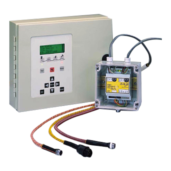
Identifying TTDM-128 Features External View [A] LCD display gives up-to-date information regarding the condition of the system TTDM-128 Icons and LEDs: Monitoring LED - green Service Required LED - Yellow Leak LED - Red Fault LED - Red (Self) Test key Silence key Reset key Menu keys... -
Page 17: The Ttdm-128 Keypad
TTDM-128 User Manual The TTDM-128 Keypad 1. Test Activates limited series of self-tests; additional self-tests are accessed through the menu (see page 34). 2. Left/Right arrow In Current Events/Status display, manually select the channel displayed. When inputing numbers or text, select digit to change. In menus, act as express keys for going to the top or bottom of long scrolled lists 3. -
Page 18: The Ttdm-128 System Display
The TTDM-128 System Display The icons represent the four states of the TTDM-128 leak detection network. The LEDs indicate which states are currently active. Green Yellow Monitoring Service Leak Fault : The Service, Leak and Fault LEDs will illuminate if an alarm condition exists on any SIM. -
Page 19: Normal Operation
TTDM-128 User Manual Normal operation Current Event/Status Display Line 1 CH01 SERVER ROOM Line 2 LEAK AT 125 M Line 3 Line 4 12 :30 21-01-2003 The LCD display is a backlit 4-line by 20-character display. If there is no activity for several minutes, the back lighting turns off, until a key is pressed. - Page 20 From the Current Event/Status display: ► Press the arrow keys to manually select the channel you require displayed. LEFT RIGHT ► Press the D arrow key to access detailed status information for the channel currently displayed described in detail on page 23. ►...
- Page 21 TTDM-128 User Manual ENTERING A PASSWORD When a user attempts to change a restricted setting, the TTDM-128 displays a password prompt. The factory default password is 00010 (to change the password, see page 29). To enter the password, proceed as follows: ▪...
- Page 22 TTDM-128 MENU STRUCTURE Current Event/Status Display Menu ---- Main Menu ---- SIM Status ---- Events History ---- SIM Address ---- select different SIM ---- System Status ---- ID sim id ---- SIM network ---- 1..current status ---- change SIM ID ---- 2..current status ---- current status ---- #...
-
Page 23: Status Of Individual Sim Channels
TTDM-128 User Manual Status of Individual SIM channels The TTDM-128 offers access to detailed real-time status information for each SIM channel. The status display for an individual SIM channel is accessed from the Current Event/Status display (the normal display mode): ►... - Page 24 Location The current location — or electrical center — of the leak (or cause of a Service alarm). If the SIM status is Normal, the Location entry is blank. Sense Cur This current (measured in µA) indicates the condition of the sensing cable.
-
Page 25: Modifying Settings For Individual Sim Channels
TTDM-128 User Manual Modifying Settings for Individual SIM Channels To change the alphanumeric tag for the selected SIM channel: ► Select the appropriate SIM channel as described previously in this section. ► Use the D arrow key to select ID, then press E NTER ►... - Page 26 SETTING UP REGIONS AND RELAYS For some systems, it may be helpful to divide a circuit of sensing cable into regions. In addition, regions are sometimes useful in setting up TT-NRM relay actions. When a length of sensing cable is divided into regions, the TTDM will identify the region in which a Service or Leak event occurs.
-
Page 27: Events History Log
TTDM-128 User Manual Example of a region setup for a 1,000 meter cable: Region No. Low Limit 251 m 501 m 751 m High Limit 250 m 500 m 750 m 1,000 m Room A Hall Room C Room D Region relay 50-01 50-02... - Page 28 H56874 4/03 www.tycothermal.com +1 (650) 474-7400...
-
Page 29: Detailed Setup
TTDM-128 User Manual Detailed Setup General Set-up Access the General Set-up menu from the Main Menu. The General Set-up menu has the following sub menus: ▪ Time/Date ▪ Language ▪ Password ▪ Special (High level password required to see this menu) TIME/DATE Use the L and R... -
Page 30: Leak Set-Up
Leak Setup The Leak Setup menu has the following submenus: ▪ ReAlarm Int (Re-Alarm Interval) ▪ Auto Reset ▪ AudibleAlarm ▪ Alarm Reflash ▪ Alarm Reset These parameters determine the alarm setting for all SIMs. Password entry is required to change them. -
Page 31: Sim Network
TTDM-128 User Manual SIM Network The SIM Network menu has the following submenus: ▪ Set SIM Address ▪ Init Network ▪ Update Network SET SIM ADDRESS This command allows the user to assign a new address to either the TTDM’s internal SIM or an external TTSIM. - Page 32 UPDATE NETWORK Use this command to update the TraceTek network when TTDM, TTSIM or TT-NRM units have been added or deleted and assigned unique addresses. When activated, the command immediately searches all possible addresses to determine what equipment has been connected. The current event status of all devices will be maintained by this command.
-
Page 33: Ttdm Network
TTDM-128 User Manual TTDM Network Access the TTDM Network menu through the Main Menu. The TTDM-Network menu has the following submenus: ▪ Baud ▪ Modem ▪ 485 Address ▪ TTDM ▪ Terminal ▪ Print Events These parameters affect only the serial port for external communications (features 22 & 27 in the diagram on page 16). -
Page 34: Self-Test
Self-Test The Self-Test menu provides access to specific user-selected test routines: ▪ UI Version ▪ Memory Tests ▪ SI Test ▪ 4-20 mA Test (see “Appendix 6 - Connection to Other Devices” for details) − Electronics Fault − SI Comm Error −... -
Page 35: Event Response
TTDM-128 User Manual Event Response Leak Detection and Location Events A LEAK ALARM When liquid is detected by sensing cable in any channel, the following occur: ▪ The audible alarm sounds. ▪ The red Leak LED illuminates. ▪ The display changes to show the channel and location of the leak. ▪... -
Page 36: Service Events
Service Events INTRODUCTION A TraceTek sensing circuit consists of two electrical loops. The SIM module constantly monitors for current passing between loops. When the system is normal, there is no current passing between the loops. When there is a leak on the system, the maximum current flows. If, however, a SIM detects a lower but significant level of current flow between the loops, the TTDM will signal a Service Alarm. -
Page 37: Fault Events
TTDM-128 User Manual TO CLEAR THE CABLE Investigate the cause of the alarm and conduct cleanup or maintenance accordingly. HINT: If material causing a service alarm is spread throughout the system, it is often useful to subdivide the system; see INVESTIGATING LEAKS AND FAULTS on page 42 for further information. -
Page 38: Multiple Events
Multiple Events SIMULTANEOUS EVENTS ON DIFFERENT SIM CHANNELS The TTDM-128 is capable of monitoring many sensing circuits. Each SIM operates independently of other SIMs in the leak detection network. The TTDM-128 tracks information for all SIM channels and is capable of handling multiple events that occur in the same time frame. - Page 39 TTDM-128 User Manual Use the Events History to track the events between the “first leak” and the “most recent event.” See “The Events History Log” section on page 27. ADDITIONAL LEAK If liquid contacts sensing cable at a significant distance from the initial leak, the module will re-alarm however it will indicate that this realarm leak distance could indicate a new leak rather than a growing leak.
- Page 40 H56874 4/03 www.tycothermal.com +1 (650) 474-7400...
-
Page 41: Maintenance
TTDM-128 User Manual Maintenance CLEANING THE MODULE To clean the outside surface, use a damp cloth or sponge. Do not use solvents or abrasive cleaners and do not open the enclosure while it is wet (it is an electrical device). FUSE REPLACEMENT The fuse on the power supply board of the TTDM-128 and TTSIM units is a 200-mA, 250- V, quick-acting microfuse. - Page 42 INVESTIGATING LEAKS AND FAULTS Alarm and locating module If the location of a leak is not apparent, it is often useful to subdivide the leak detection circuit. To accomplish this, it is best to have a TraceTek Portable Test Box (PTB) or extra Sensor Interface Module, and an extra Modular End Termination.
-
Page 43: Appendix 1 -Events Glossary
TTDM-128 User Manual Appendix 1 - Events Glossary Type of Message Description Event Power Power Down The time the power was last supplied to the TTDM-128 is stored in nonvolatile memory and is entered into the Events History log when power is restored. Restart The Events History log records when power is supplied to the unit or when the unit is manually restarted. - Page 44 Service Displayed when the condition requiring service has been Clear cleared (for example, the sensing cable is clean and dry). User Settings Whenever any user-setup parameter is changed, the Action Changed event is logged in the Event History Alarm Event History item Silenced Reset Event History item...
-
Page 45: Appendix 2 -Connection To Other Devices
TTDM-128 User Manual Appendix 2 - Connection to Other Devices : All connections to external devices are made at the TTDM-128. RELAYS TTDM-128 has three relays: Service Leak Fault Relay Logic Each relay provides two Form-C relay contacts, with normally open and normally closed contacts both provided. - Page 46 Close on Alarm Relays wired in parallel 15 16 17 18 19 20 21 22 23 24 25 26 27 28 29 30 31 32 Monitoring circuit (close on alarm) OPTIONAL 4-20 MA INTERFACE The TTDM-128 can be equipped with an analog 4-20 mA interface which can communicate the status of a selected SIM channel.
Need help?
Do you have a question about the TraceTek TTDM-128 and is the answer not in the manual?
Questions and answers