Table of Contents
Advertisement
Quick Links
Advertisement
Table of Contents

Subscribe to Our Youtube Channel
Related Manuals for Barmesa Pumps BVL Series


Summary of Contents for Barmesa Pumps BVL Series
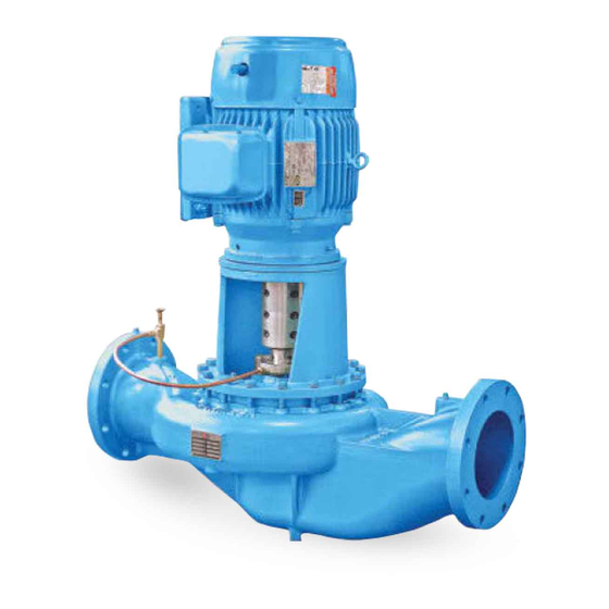
- Page 1 Installation, Operation & Maintenance Manual Split Coupled Vertical In-line Pumps BVL series 1 - 500 HP barmesa.com 8 x 8 x 13 4 x 4 x 10 3 x 3 x 6 IMPORTANT! - Read all instructions in this manual before operating or servicing a pump.
-
Page 2: General Safety Information
IMPORTANT! - Barmesa Pumps is not installations where there is responsible for losses, injury or IMPORTANT! - Prior to installation, human contact with pumped fluid. -
Page 3: Specifications And Dimensions
Specifications & Dimensions CASING: Cast iron ASTM A-48 class 30, horizontal suction and discharge. 150 PSI rated flange. With lubrication, drainage and pressure connections. IMPELLER: Close type, cast iron ASTM A-48 class 30 or bronze ASTM-B584, Gr. C84400. SPLIT COUPLING: Aluminum 6061-T6. -
Page 4: Receiving And Installation
Receiving & Installation 4Receiving inspection 4Typical installation diagrams for BVL's Upon receiving the pump, it should inspected damage shortages. If damage has occurred, file a claim immediately with the company that delivered the pump. If the manual is removed from the packaging, do not lose or misplace. -
Page 5: Installation
Installation HANGERS SUPPORTED THE WEIGHT OF THE FILLED PIPING, PUMPS AND FITTINGS SYSTEM INLET FLUSH LINE FLO-TREX VALVE RECOMMENDED FIELD FLO-TREX VALVE PRESSURE GAUGE PIPING ARRANGEMENT SUCTION GUIDE DRAIN DRAIN NEOPRENE PIPE SUPPORT CONNECTION INSOLATION FLOOR SADDLE SUPPORT WITH ADDITIONAL PIPE SUPPORTS barmesa.com STANCHION PLATES INSOLATION PADS... - Page 6 Installation 4Discharge Recommended to use robust and self-supported piping to maintain the pump stable and firm during operation. Due to the high energy cost or BHP necessary overdue friction generated by using a small diameter pipe, usually a large diameter pipe is used in the discharge side.
-
Page 7: Operation And Maintenance
35 mm (1-3/8”) between the Install a foot valve in the suction side your Barmesa Pumps distributor for pump shaft and motor shaft. and fill with liquid through the upper more information. -
Page 8: Maintenance
Maintenance Repeat pattern until all the bolts Make sure both motor shaft and Ÿ Ÿ have been completely tighten. pump shaft rotate freely. Do not over tighten this bolts, it Adjust the mechanical seal may damage the pumps casing Ÿ and stationary seal. -
Page 9: Repair Parts
Repair Parts When ordering repair parts always provide the following information: Pump serial number: Ÿ Part description: Ÿ Pump model: Ÿ Quantity requiered: Ÿ Pump Part number: Ÿ Shipping instructions: Ÿ MECHANICAL SEAL ROTARY PART GLAND MECH. (ITEM 62) SEAL BOLT (ITEM 52) GLAND MECH. - Page 10 Repair Parts GLAND MECH. SEAL BOLT (ITEM 52) GLAND MECH. SEAL (ITEM 54) FLUSH LOCKWASHER CONNECTOR (ITEM 163) MECHANICAL SEAL STATIONARY FACE (ITEM 62) GLAND GASKET (ITEM 55) barmesa.com MECHANICAL SEAL ROTARY PART (ITEM 62) RETAINING RING (ITEM 160) PUMP'S SHAFT COUPLING OR STUFFING BOX EXPLODED VIEW...
- Page 11 Repair Parts SPLIT COUPLING MOTOR'S SHAFT SPLIT COUPLING SPACE BETWEEN SHAFTS PUMP'S SHAFT barmesa.com ITEM 140 MOTOR SPACE PUMP ITEM 62 ITEM 147 PART # FRAME Ø SHAFT'S BETWEEN SHAFT'S Ø PART # PART # 30405001 143-145 TC ⁷⁄₈" 1³⁄₈" 31030501 30405002 182-184 TC...
- Page 12 Friction Table FRICTION TABLE IN METERS x 100m OF PIPE PIPING DIMENSIONS IN INCHES LITERS GALLONS 1" 1 1/4" 1 1/2" 2" 2 ½" 3" 4" 5" 6" 8" 10" MINUTE MINUTE 4.54 6.86 1.77 9.62 2.48 16.2 1.53 20.6 5.22 2.42 25.1...
- Page 13 Friction Table Equivalent length in meters of straight pipe and valve connections for calculating friction. DIAMETER PART DESCRIPTION 1" 1¼" 1½" 2" 2 ½" 3" 4" 5" 6" STANDARD 90° 0.84 1.07 1.22 1.68 1.98 2.44 3.35 4.12 4.88 ELBOW MEDIUM RADIUS 0.69 0.92 1.07 1.37 1.68 2.14 2.75 3.51 4.27 ELBOW 90°...
- Page 14 Exploded View COUPLING & BUSHING SUBASSEMBLY barmesa.com IMPELLER & SHAFT SUBASSEMBLY...
-
Page 15: Exploded View
Exploded View SUBASSEMBLY COUPLING & BUSHING barmesa.com SUBASSEMBLY IMPELLER & SHAFT VERTICAL IN-LINE PUMP... - Page 16 Exploded View SUCTION'S barmesa.com FLANGE DISCHARGE'S PUMP'S FLANGE SHAFT MECHANICAL SEAL & FLUSH...
-
Page 17: Parts List
Parts List ITEM DESCRIPTION MATERIAL SHAFT STAINLESS STEEL 416 IMPELLER KEY CARBON STEEL 1018 ADAPTER CAST IRON ASTM-A48, CLASS 30 WASHER CARBON STEEL MOTOR CAPSCREW COUPLING CAST IRON ASTM-A48, CLASS 30 SEAL PLATE BUSHING GRAPHITE SEAL COVER CAPSCREW STAINLESS STEEL 304 SEAL GLAND STAINLESS STEEL 316 MALE STRAIGHT CONNECTOR... -
Page 18: Troubleshooting Chart
That the motor is suitable for the pump. NOTE: Barmesa Pumps assumes no responsibility for damage or injury due to disassembly in the field. Disassembly of the pumps or supplied accessories other than at Barmesa Pumps or its authorized service centers, automatically voids warranty. - Page 19 barmesa.com...
Need help?
Do you have a question about the BVL Series and is the answer not in the manual?
Questions and answers