
Subscribe to Our Youtube Channel
Related Manuals for Barmesa Pumps BMV Series


Summary of Contents for Barmesa Pumps BMV Series
- Page 1 Installation, Operation & Maintenance Manual Vertical Multi-Stage series barmesapumps.com IMPORTANT! - Read all instructions in this manual before operating or servicing a pump.
- Page 2 IMPORTANT! - Barmesa Pumps is not installations where human systems, that are required to reduce responsible for losses, injury or contact with pumped fluid.
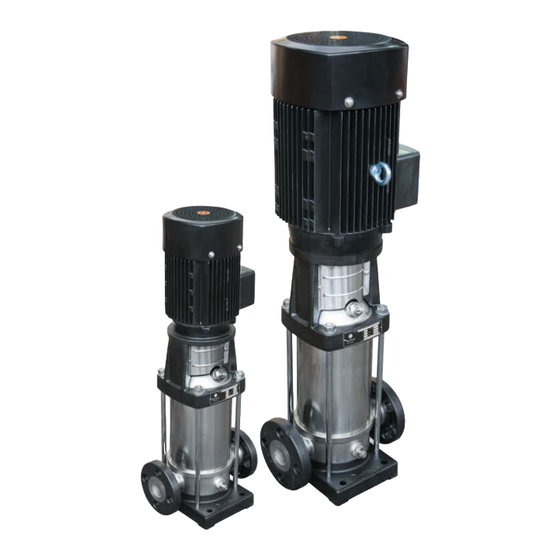
- Page 3 Applications & Conditions Description The non-self priming vertical multi-stage centrifugal pump is driven by a standard electric motor. The motor output shaft directly connects with the pump shaft through a coupling. The pressure-resistant cylinder and flow passage components are fixed between pump head and inlet & outlet section with stay bolts. The inlet and outlet are located at the pump bottom at the same plane.
- Page 4 Definition of Model Nomenclature B M V 1 - 2 5 0 - 3 0 3 PHASE STAGE (x10) RATED FLOW (m³/h) MULTI-STAGE PUMP Nameplate To each pumping equipment is placed an identification plate, as shown below: barmesapumps.com...
- Page 5 Structure The pump is mainly composed of motor, pump head, diffuser, impeller, cylinder, inlet & outlet chamber, pump shaft, mechanical seal and so on. Refer to Fig. 1. Key parts of the pump, diffuser, impeller, cylinder, shaft, arc all made of stainless steel. Also the material of ...
- Page 6 Structure Table 1A: (BMV1 - BMV4) PART No. MODEL ITEM DESCRIPTION QTY. UNIT MOTOR 70120001 BMV1-90-103 COUPLING 70120002 BMV1-110-153 HEXAGON SOCKET HEAD SCREW 70120003 BMV1-130-153 COUPLING GUARD (NO NICK) 70120004 BMV1-170-203 MECHANICAL SEAL 70120005 BMV1-210-303 SCREW M4x8 70120006 BMV1-230-303 COUPLING 70120011 BMV2-60-153 SCREW, WASHER...
- Page 7 Structure Figure 1B: (BMV8 - BMV20) barmesapumps.com 41 42 14 43 44 For Repair Part Please supply: Model Number and Serial as shown on Name Plate, and Part Description and Part Number as shown on Parts List.
- Page 8 Structure Table 1B: (BMV8 - BMV20) PART No. MODEL ITEM DESCRIPTION UNIT MOTOR 70120041 BMV8-50-403 COUPLING 70120042 BMV8-60-503 HEXAGON SOCKET HEAD SCREW 70120043 BMV8-80-753 MECHANICAL SEAL 70120044 BMV8-100-1003 COUPLING GUARD (NO NICK) 70120045 BMV8-l20-1003 SCREW, WASHER 70120046 BMV8-l40-1503 COUPLING BMV12-20-303 SCREW M4x8 BMV12-50-753 AIR VENT NUT...
- Page 9 Structure Figure 1C: (BMV32 - BMV65) barmesapumps.com For Repair Part Please supply: Model Number and Serial as shown on Name Plate, and Part Description and Part Number as shown on Parts List.
- Page 10 Structure Table 1C: (BMV32 - BMV65) PART No. MODEL ITEM DESCRIPTION QTY. UNIT MOTOR 70120061 BMV32-32-1003 COUPLING 70120062 BMV32-42-1503 HEXAGON SOCKET HEAD SCREW 70120063 BMV32-52-2003 SCREW M4x8 70120064 BMV32-60-2503 BRACKET 70120065 BMV32-82-3003 COUPLING GUARD 70120066 BMV32-90-4003 HEX. SCREW, NUT, WASHER 70120073 BMV42-20-2003 HEXAGON SOCKET HEAD SCREW...
-
Page 11: Installation And Connection
Installation & Connection Handling When lifting the pump, use the motor eyebolts. Installation The pump should be installed in a well ventilated and frost-free position. The distance between pump- motor and other objects should be at least 6 inches in order to have enough air to cool the motor. The inlet pipe shall be as short as possible in order to reduce the head loss of the inlet. - Page 12 Dimensions Pump size and dimension is as follows. Figure 4 G1/2 barmesapumps.com n-D1 G1/2 4-D2 Table 2 MODELS DIMENSIONS (mm) 100 110 140 145 4x Ø14 4x Ø18 8x Ø18 n-D1 RATED PN25 PN25-40 PN16-25 PN16 FLOW...
- Page 13 Dimensions Table 3 DIMENSION (inches) WEIGHT MODEL B1+B2 (lb) BMV1-90-103 BMV1-110-153 BMV1-130-153 BMV1-170-203 BMV1-210-303 BMV1-230-303 BMV2-60-153 BMV2-70-203 BMV2-110-303 BMV2-150-403 BMV2-180-503 BMV3-80-153 BMV3-110-203 BMV3-150-303 BMV3-170-303 BMV3-190-403 BMV3-230-403 BMV3-250-503 BMV4-60-303 BMV4-80-403 BMV4-100-503 BMV4-120-503 BMV4-160-753 BMV8-50-403 barmesapumps.com BMV8-60-503 BMV8-80-753 BMV8-100-1003 BMV8-120-1003 BMV8-140-1503 BMV12-20-303 BMV12-50-753 BMV12-70-1003 BMV12-100-1503...
- Page 14 Installation & Connection Electrical connection The electrical connections should be carried out by an authorized electrician. To make sure the motor is suitable for the power supply, cables of the motor must be connected to power supply according to the figure on the terminal box and the motor nameplate.
-
Page 15: Start-Up, Operation & Maintenance
Start-up, operation & maintenance. Before opening the terminal box, please shut off the power supply to prevent an electric shock. DANGER Before opening the coupling guards, stop pump first to prevent body injuries. WARNING When installing the pump, please fix the foundation bolts to prevent pump from falling. WARNING Please fill grease to the pump when it required. - Page 16 Start-up, operation & maintenance. Check whether it turns correctly. To make sure all pipe lines are connected tightly and can supply water normally. The valves in the inlet pipe line are completely opened and the outlet valve shall be opened slowly after ...
-
Page 17: Assemble & Disassemble
Assemble & disassemble 1. For BMV 1, 2, 3, 4 Put the circlip cover on the shaft, and then fit the sleeve, impeller, impeller sleeve, diffuser, support diffuser. Continue the assemble order till the last impeller is fitted. Then fit the impeller cover, washer, screw the nut. - Page 18 Assemble & disassemble 3. For BMV 32, 42, 65 Put the inlet & outlet chamber on the base plate, fit flanges on inlet & outlet chamber at two sides, and fit the inducer. Put the first impeller on the shaft, tighten the nuts and put the impeller on the neck ring base of inducer, ...
- Page 19 Fault Finding & Solution Chart Caution: Before removing the terminal box cover and before any removal/dismantling of the pump, make sure that the power supply has been switched off. Table 5 FAULT CAUSE SOLUTION REMARKS a) Power supply failure. a)Check power supply. b) Fuses are blown.
- Page 20 Fault Finding & Solution Chart FAULT CAUSE SOLUTION REMARKS a) Suction pipe is blocked by a) Check and clean suction impurities. pipe. b) Foot valve or check valve is b) Check and repair foot valve Pump runs but gives closed. or check valve.
Need help?
Do you have a question about the BMV Series and is the answer not in the manual?
Questions and answers