Parker Compax3 Installation Manual
Hydraulics controller
Hide thumbs
Also See for Compax3:
- Operating instructions manual (470 pages) ,
- Start-up (40 pages) ,
- Installation manual (28 pages)
Table of Contents
Advertisement
Quick Links
Compax3
Compax3 Fluid Installation Manual
Hydraulics controller
We reserve the right to make technical changes.
The data correspond to the current status at the time of printing.
Electromechanical Automation
Release R08-0
20.06.08 11:26
C3Manager-Compax3F
Unterlagen / Software
user guides / tools
manuels / tools:
Compax3 - DVD (english, deutsch, français)
+
Compax3F Installations-Handbuch deutsch
Compax3F Installation Manual english
192-121100 N6 June 2008
192-121100 N6
June 2008
Advertisement
Table of Contents

Related Manuals for Parker Compax3


Summary of Contents for Parker Compax3
- Page 1 Compax3 Fluid Installation Manual Hydraulics controller C3Manager-Compax3F Unterlagen / Software user guides / tools manuels / tools: Compax3 - DVD (english, deutsch, français) Compax3F Installations-Handbuch deutsch Compax3F Installation Manual english 192-121100 N6 June 2008 Release R08-0 We reserve the right to make technical changes.
- Page 2 Reg. Nr. 36 38 E-mail: sales.automation@parker.com mailto:sales.automation@parker.com Parker Hannifin GmbH & Co. KG - registered office: Bielefeld - Amtsgericht: Bielefeld HRA 14808 Personally liable shareholder: Parker Hannifin Management GmbH - Amtsgericht: Bielefeld HRB 35489 executive board: Dr. Gerd Scheffel, Günter Schrank, Christian Stein, Kees Veraart, Hans Wolfs - Chairman of the board: Hansgeorg...
-
Page 3: Notes On The Documents Supplied
Parker Motion Control products, can be found on the C3 DVD. Several axes are managed in a common project. The Compax3 ServoManager is integrated per "Plug & Play" for each Compax3 axis. The configuration, optimization,.. take place in the same way as in an independently working C3 ServoManager. -
Page 4: C3 Servomanager
Notes on the Documents Supplied Hydraulics controller C3 ServoManager Installation of the C3 The Compax3 ServoManager can be installed directly from the Compax3 ServoManager DVD. Click on the appropriate hyperlink or start the installation program "C3Mgr_Setup_V..exe" and follow the instructions. - Page 5 Notes on the Documents Supplied Connection between Your PC is connected with Compax3 via a RS232 cable (SSK1). Cable SSK1 (COM 1/2-interface on the PC to X10 on the Compax3 or via adapter PC - Compax3 SSK32/20 on programming interface of Compax3H).
-
Page 6: Table Of Contents
Warranty conditions ................11 Conditions of utilization for CE-conform operation......12 3. Compax3F device description...............13 State of delivery ..................13 Plug and connector assignment Compax3 Fluid ........ 13 3.2.1. Meaning of the front panel LEDs (via X10)............13 3.2.2. Plug and connector assignment ................ 14 3.2.3. -
Page 7: Introduction
Parker EME Introduction 2. Introduction In this chapter you can read about: Device assignment Compax3 Fluid..................7 Type specification plate Compax3 Fluid................8 Packaging, transport, storage ....................9 Safety Instructions ......................10 Warranty conditions......................11 Conditions of utilization for CE-conform operation .............12 Device assignment Compax3 Fluid... -
Page 8: Type Specification Plate Compax3 Fluid
Introduction Hydraulics controller Type specification plate Compax3 Fluid You will find the exact description of the device on the type specification plate, which is located on the right side of the device: Type specification plate Compax3 Fluid: Explanation: Type designation The complete order designation of the device (2, 6, -9...) -
Page 9: Packaging, Transport, Storage
Parker EME Introduction Packaging, transport, storage Packaging material and transport Caution! The packaging material is inflammable, if it is disposed of improperly by burning, lethal fumes may develop. The packaging material must be kept and reused in the case of a return shipment. -
Page 10: Safety Instructions
Introduction Hydraulics controller Safety Instructions In this chapter you can read about: General hazards .........................10 Safety-conscious working....................10 Special safety instructions ....................11 2.4.1. General hazards General Hazards on Non-Compliance with the Safety Instructions The device described in this manual is designed in accordance with the latest technology and is safe in operation. -
Page 11: Special Safety Instructions
Fix the devices according to our mounting instructions. (see page 23) We cannot provide any guarantee for any other mounting methods. Note on exchange of options Compax3 options must be exchanged in the factory to ensure hardware and software compatibility. 192-121100 N6 June 2008... -
Page 12: Conditions Of Utilization For Ce-Conform Operation
Shielding connection of the valve cables The cable should be fully screened and connected to the Compax3 housing. We offer a special Shield connecting terminal as accessory item (ZBH./...). The shield of the valve cable must also be connected with the valve housing. The fixing (via plug or screw in the terminal box) depends on the valve type. -
Page 13: Compax3F Device Description
Compax3 is delivered without configuration! After switching on the 25VDC supply, the red LED is flashing while the green LED is dark. Please configure the device with the help of the Windows-Software ”Compax3 – ServoManager”! Plug and connector assignment Compax3 Fluid In this chapter you can read about: Meaning of the front panel LEDs (via X10) ................13... -
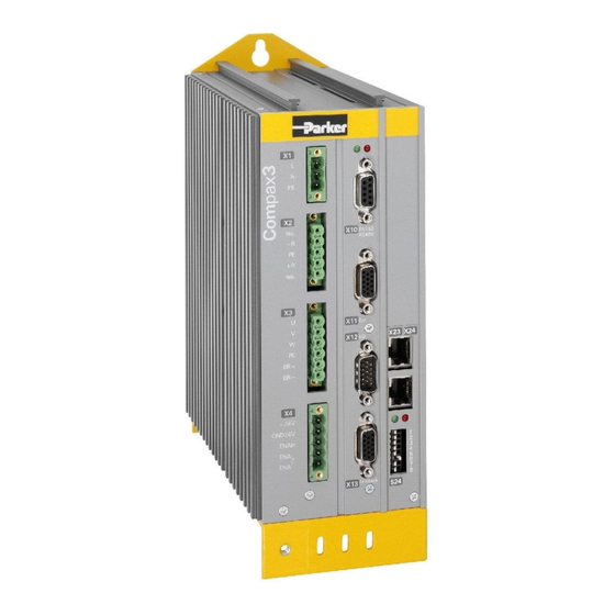
Page 14: Plug And Connector Assignment
Compax3F device description Hydraulics controller 3.2.2. Plug and connector assignment LED1 Analog Inputs Analog Outputs 24 VDC power supply RS232/RS485 2. Feedback Type Inputs/Outputs 1. Feedback Type Always switch devices off before wiring them! 192-121100 N6 June 2008... -
Page 15: Plug And Connector Assignment Complete
Parker EME Compax3F device description 3.2.3. Plug and connector assignment complete In detail: The fitting of the different plugs depends on the extension level of Compax3. In part, the assignment depends on the Compax3 option implemented. Compax3F X20/1 X10/1 X10/1... -
Page 16: Analog Input (Plug X1)
Requirement: Connection cable Use shielded cables. Shield connection of the cables The cable should be fully screened and connected to the Compax3 housing. We offer a special Shield connecting terminal as accessory item (ZBH./...). 3.2.4.1 Wiring of the analog inputs... -
Page 17: Analog Output (Plug X2)
All outputs are short-circuit proof. Requirement: Connection cable Use shielded cables. Shield connection of the cables The cable should be fully screened and connected to the Compax3 housing. We offer a special Shield connecting terminal as accessory item (ZBH./...). 3.2.5.1 Wiring of analog outputs... -
Page 18: Voltage Supply (Plug X3)
Combicon 5mm X3 Pin +24 V 24 VDC (power supply) Gnd 24 V Voltage supply 24VDC Controller type Compax3 F001 D2 Voltage range 21 - 27VDC Mains module with switch-on current limitation, due to capacitive load Fuse MTP miniature circuit breaker or "delayed action fuse", due to capacitive load... -
Page 19: Rs232 / Rs485 Interface (Plug X10)
Parker EME Compax3F device description 3.2.7. RS232 / RS485 interface (plug X10) Interface selectable by contact functions assignment of X10/1: X10/1=0V RS232 X10/1=5V RS485 RS232 (Sub D) (Enable RS232) 0V RS485 2-wire RS485 two wire (Sub D) Pin 1 and 9 jumpered externally Enable RS485 (+5V) res. -
Page 20: Analog / Encoder (Plug X11)
Clock+ STSP+ STSP- DATA- DATA+ Max. start/stop time is 1.6ms (over 4.15m). 3.2.8.1 Connections of the encoder interface Compax3 1K Ω 121 Ω RS422 Transceiver 10nF A B N 1K Ω The input connection is available in triple (for A & /A, B & /B, N & /N) -
Page 21: Digital Inputs/Outputs (Plug X12)
The exact assignment depends on the the device type! You will find the description of the device-specific assignment in the online help which can be opened from the Compax3 – ServoManager. Maximum capacitive loading of the outputs: 50nF (max. 4 Compax3 inputs). 3.2.9.1 Connection of the digital Outputs/Inputs... -
Page 22: Feedback (Connector X13)
+5V (Pin 4) is measured and controlled directly at the end of the line via Sense – and Sense +. Maximum cable length: 100m Caution! Pin 4 and Pin 5 must under no circumstances be connected! 3.2.10.1 Connections of the encoder interface Compax3 1K Ω 121 Ω RS422 Transceiver 10nF A B N 1K Ω... -
Page 23: Mounting And Dimensions
Parker EME Compax3F device description 3.2.11. Mounting and dimensions Mounting: 3 socket head screws M5 or by direct snapping on a 35mm supporting rail (according to DIN EN 50 022), Mounting material: DIN rail clip and distance piece available as accessories - Set... -
Page 24: Specifications
Specifications Hydraulics controller 4. Specifications Voltage supply 24VDC Controller type Compax3 F001 D2 Voltage range 21 - 27VDC Mains module with switch-on current limitation, due to capacitive load Fuse MTP miniature circuit breaker or "delayed action fuse", due to capacitive load Current drain of the device 0.8A (max. - Page 25 Parker EME Specifications Supported valves and feedback systems Valves D1*FH series Absolute encoder Analog 0..20mA, 4..20mA, ±10V Start/Stop - interface SSI interface EnDat 2.1-interface 1VSS (max. 400kHz) Interface, 13.5bits / graduationof the scale RS422 encoder (max. 5MHz), internal quadrature of the resolution...
- Page 26 Specifications Hydraulics controller UL certification conform to UL: USL according to UL508 (Listed) CNL according to C22.2 No. 142- M1987. (Listed) Certified E-File_No.: E198563 The UL certification is documented by a ”UL” logo on the device (type specification plate). ”UL” logo Detailed information on the technical data of the Compax3F devices can be found in the Help-files of the individual Compax3F device types.
- Page 27 Parker EME Specifications 192-121100 N6 June 2008...
-
Page 28: Index
Analog / Encoder (plug X11) • 20 State of delivery • 13 Analog Input (plug X1) • 16 Analog Output (plug X2) • 17 Type specification plate Compax3 Fluid • 8 C3 ServoManager • 4 Compax3F device description • 13 Conditions of utilization for CE-conform Usage in accordance with intended purpose •...
Need help?
Do you have a question about the Compax3 and is the answer not in the manual?
Questions and answers