Sign In
Upload
Manuals
Brands
Parker Manuals
Controller
Compax3 Fluid T40
Parker Compax3 Fluid T40 Manuals
Manuals and User Guides for Parker Compax3 Fluid T40. We have
6
Parker Compax3 Fluid T40 manuals available for free PDF download: Operating Instructions Manual, Installation Manual, Start-Up
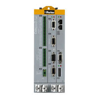
Parker Compax3 Fluid T40 Operating Instructions Manual (470 pages)
Hydraulics controller
Brand:
Parker
| Category:
Controller
| Size: 9 MB
Table of Contents
Table of Contents
3
1 Introduction
12
Device Assignment Compax3 Fluid
12
Type Specification Plate Compax3 Fluid
13
Safety Instructions
14
General Hazards
14
Safety-Conscious Working
14
Special Safety Instructions
15
Warranty Conditions
15
Conditions of Utilization for CE-Conform Operation
15
2 Positioning with IEC61131-3
17
3. Compax3F Device Description
21
In this Chapter You Can Read About: Meaning of the Front Panel Leds (Via X10)
21
Plug and Connector Assignment
22
Plug and Connector Assignment Complete
23
Analog Input (Plug X1)
25
Wiring of the Analog Inputs
25
Analog Output (Plug X2)
26
Wiring of Analog Outputs
26
Voltage Supply (Plug X3)
27
RS232 / RS485 Interface (Plug X10)
27
Analog / Encoder (Plug X11)
28
Connections of the Encoder Interface
29
Digital Inputs/Outputs (Plug X12)
29
Connection of the Digital Outputs/Inputs
30
Feedback (Connector X13)
30
Connections of the Encoder Interface
31
Profibus Connector X23 with Interface I20
32
Adjusting the Bus Address
32
Function of the Bus Leds
32
Canopen Connector X23 Interface I21
33
Adjusting the Bus Address
33
Function of the Bus Leds
34
Devicenet Connector X23
35
Adjusting the Bus Address
35
Function of the Bus Leds
36
Ethernet Powerlink (Option I30) / Ethercat (Option I31) X23, X24
36
Meaning of the Bus Leds (Ethernet Powerlink)
37
Set Ethernet Powerlink (Option I30) Bus Address
37
Meaning of the Bus Leds (Ethercat)
38
Mounting and Dimensions
40
In this Chapter You Can Read about
21
3 Compax3F Device Description
21
State of Delivery
21
Plug and Connector Assignment Compax3 Fluid
21
Meaning of the Front Panel Leds (Via X10)
21
Parker Eme 4. Setting up Compax3
41
4 Setting up Compax3
41
Configuration
41
C3Hydraulicsmanager
44
Function Description
44
Structure of the Databases
44
Compax3F Structure Image
45
Drive Configuration
46
Configuring Drive1
47
Position Feedback System Drive1
47
Cylinder / Motor Selection
48
Load Configuration Drive1
48
Configuring Drive2
49
Pressure Sensors
49
Sensors
49
Force Sensor Drive 1
50
Pressure and Force Sensor Drive 2
51
Valve Configuration
51
Selection and Configuration of the Valves
52
Defining the Reference System
53
Position Transducer
53
4.1.8.2 Machine Zero
54
In this Chapter You Can Read About: Positioning after Homing Run
54
Machine Zero
54
Machine Zero Speed and Acceleration
55
Machine Zero Modes Overview
56
Homing Modes with Home Switch (on X12/14)
58
Machine Zero Modes Without Home Switch
65
Adjusting the Machine Zero Proximity Switch
69
Travel Limit Settings
70
Change Assignment Direction Reversal / Limit Switches
74
Change Initiator Logic
74
Debouncing: Limit Switch, Machine Zero and Input 0
74
Ramp Upon Error and Switch to Currentless
74
Limit and Monitoring Settings of Force
75
Force Window - Force Achieved
75
Hydraulic Corner Power Limitation
76
Maximum Control Deviation of Force Controller
76
Maximum Force
76
Positioning Window - Position Reached
77
Following Error Limit
78
Maximum Permissible Speed
78
Encoder Simulation
79
Recipe Table
80
Error Response
80
Configuration Name / Comments
81
Configuring the Signal Source
82
Physical Source
82
Encoder A/B 5V, Step/Direction or SSI Feedback as Signal Source
82
10V Master Speed
85
Internal Virtual Master
85
HEDA Master Signal Source
85
Optimization
87
Optimization Window
88
Scope
89
Monitor Information
89
4.3.2.2 User Interface
90
User Interface
90
N04 June
91
Oscilloscope Operating Mode Switch
91
Setting the Time Basis XDIV
91
Settings for Channels 1
92
Special Functions
93
Example: Setting the Oscilloscope
95
Control Loop Dynamics
97
Trigger Settings
93
4.3.3.1 Preparatory Settings for the Controller Alignment
98
Checking the Feedback Direction and the Valve Output Polarity
98
In this Chapter You Can Read About: Configuring the Device
98
Preparatory Settings for the Controller Alignment
98
Compensation of Non-Linearities of the Distance
99
Checking the Open Loop Gain
101
Filter Alignment
101
Signal Filtering with External Command Value
102
Controller Optimization
102
Controller Structure of Main Axis
105
Controller Strucutre Auxiliary Axis
106
Feedforward Main Axis (Status Controller)
107
Feedforward Auxiliary Axis (Status Controller)
108
4.3.3.7 Position Controller Main Axis (Status Controller)
109
In this Chapter You Can Read About: Object 2200.24: Filter - Following Error
109
Object 2200.11: Filter - Following Error
109
Position Controller Main Axis (Status Controller)
109
Object 2200.30: Internal Window I-Term
110
Object 2200.31: External Window I-Term
110
Object 2200.37: I-Term
110
Object 2200.38: P-Term
110
Object 2100.13: Speed Feedback
111
Object 2200.32: Positive Limit I-Term
111
Object 2200.33: Negative Limit I-Term
111
Object 2100.14: Acceleration Feedback
112
Object 2210.8: Filter Control Signal
112
Position Controller Auxiliary Axis (Status Controller)
113
Filter Main Axis
116
Filter Auxiliary Axis
117
Analog Input
118
Force-/Pressure Control Main Axis
123
Force-/Pressure Control Auxiliary Axis
127
Output Signal Conditioning 0
131
Step-By-Step Optimization
138
Parker Eme
139
In this Chapter You Can Read About: Parameters for Manual Movement/Jogging Mode and Test Movement
139
Limit Valve Set Value
140
Move Drive Controlledly
140
Check Connection Assignment of the Pressure Sensors
141
Check Input Offset or Zero of the Pressure Sensors
141
Check Sense of Direction
141
Set Valve Offset
141
Direction Dependent Gain
142
Optimization of Position Controller
142
Optimization of Pressure/Force Controller
145
Input Simulation
147
Calling up the Input Simulation
147
Functionality
148
Setup Mode
149
Motion Objects in Compax3
150
Profileviewer for the Optimization of the Motion Profile
150
Mode 1: Time and Maximum Values Are Deduced from Compax3 Input Values
151
Mode 2: Compax3 Input Values Are Deduced from Times and Maximum Values
151
5 Motion Control
152
Programming Based on IEC61131-3
152
Prerequisites
152
Codesys / Compax3 Target System (Target Package)
153
Program Development and Test
153
Function Range Supported
154
Languages Supported
154
Operators Supported
154
Recipe Management
154
Standard Functions Supported
155
Standard Function Modules Supported
156
Data Types Supported
157
Recipe Table with 9 Columns and 32 Lines
157
Retain Variables
157
Access to the Compax3 Object Directory
158
Cycle Time
158
Maximum Program Size
158
Compilation, Debugging and Down/Upload of IEC61131 Programs
159
General Rules / Timing
160
Library Constants
161
Status Diagrams
162
Status Diagram of Compax3F Main Axis
162
Status Diagram of Compax3F Auxiliary Axis
163
Status Diagram of the Virtual Master
164
Control Functions
165
Activation of the Drive (Mc_Power)
165
Stop (Mc_Stop)
166
Mc_Stop at Pressure/Force Control
167
Mc_Stop: Example 1
167
Mc_Stop: Example 2
168
C3_Setcontrolmode
169
Reading Values
170
Reading the Current Position (Mc_Readactualposition)
170
Read Access to the (C3_Readarray) Array
172
Reading the Device Status (Mc_Readstatus)
173
Determine Valve/Range Parameters (C3_Getsystemfingerprint)
174
Important Notes
176
Procedure When Working with the C3_Getsystemfingerprint
177
Positioning Functions (Standard)
178
Value Range for Positioning Parameters
178
Absolute Positioning (Mc_Moveabsolute)
179
Position Mode in Reset Operation
182
Description of Jerk
183
Relative Positioning (Mc_Moverelative)
184
Additive Positioning (Mc_Moveadditive)
186
Continuous Positioning (Mc_Movevelocity)
188
Manual Operation (C3_Jog)
190
Homing (Mc_Home)
192
Electronic Gearbox (Mc_Gearin)
195
Superimposed Motion
198
Dynamic Positioning
198
Superimposed Positioning (Mc_Movesuperimposed)
199
Zero Point Shift Caused by Superimposed Positioning (C3_Shiftposition)
201
Adjust Force / Pressure (C3_Pressureforceabsolute)
203
Dynamic Switching: Position- on Force/Pressure - Adjustment
204
Switching: from Force to Position Mode (C3_Pq)
205
Parker Eme 5.10 Cam Control
207
Cam Control
207
Introduction: Electronic Cam Control
208
Function Principle
209
Overview
210
Basics
211
Cam Types
211
Cam Parameters / Terms
212
Basic Procedure
213
Generating Cams
214
Introduction to the Camdesigner (Example)
215
Cam Functions of the Compax3 Servomanager / Motion Laws
220
Cam Function Structure
224
Function Modules of the Cam
224
Signal Image
225
Parker Eme 5.10.5.3 Cam Reference Systems
229
Cam Reference Systems
229
Relative Master Reference Without Offset
229
N04 June
230
Relative Master Reference with 180° Offset
230
Absolute Master Reference Without Offset
231
Absolute Master Reference with 180° Offset
232
Relative Slave Reference
232
Absolute Slave Reference
235
Master Signal Source
235
C3_Setmaster
236
Setting the Position of the Selected Master Source
236
Recording the Position of the Selected Master Source (C3_Mastercontrol)
237
Control of the Cam Generator (C3_Camtableselect)
240
C3_Masterconfig
243
Master Signal Phase Shift (Mc_Phasing)
244
Alignment of the Slave Axis
246
Start Cam / Coupling
246
Exiting the Active Curve with Coupling Movement (C3_Camout)
257
Step 1: C3 Servomanager
261
Step 2: Connect Motor
261
Step 3: Supply & I/O Wiring
261
Step 4: RS232 Connection & C3 Servomanager
261
Steps for Cam Generation
261
Step 5: Set Compax3 Device Type
262
Step 6: Configuration
262
Step 7: Selecting Master Signal Source
262
Step 8: Generating the Cam
262
Step 10: Starting and Monitoring Cam
263
Step 9: Create IEC Program
263
Cam Applications
264
Example 1: Single Start of a Closed Cam
264
Example 2: Change between Single Start of an Open Cam and POSA
267
Example 3: Single Start for Run through Curve 5 Times
269
Example 4: Composing Curves
271
Example 5: Cyclic Operation with Event-Triggered Change of Curve
274
Example 6: Operation with Curve Segments and Standstill Area
276
Example 7: Curve Operation with Slave Reg Synchronization
279
Example 8: Curve Operation with Master Reg Synchronization
281
Example Case of Damage
284
Application Note: Drift
286
Cam Switching Mechanism
288
Cam Switching Mechanism Function Overview
288
Example of Cam Function
289
Examples of a Cam Cycle
289
(C3_Outputselect)
291
Redirect the Fast Cams Directly to the Physical Output
291
Objects of the Cam Switching Mechanism
292
Behavior Depending on the Travel Direction
293
Behavior of the Switch-On/Switch-Off Anticipation
293
Switch-On Anticipation Is Corrected Via Reset Distance
295
Switching Behavior with Reset Operation
295
Hysteresis
296
Note: no Switching Operation with Overlapping Cams
296
Codesys-Project for the Configuration of the Cams
297
Example: Working with Fast Cams
298
Acknowledging Errors (Mc_Reset)
300
Error Handling
300
Reading Axis Errors (Mc_Readaxiserror)
301
Set Error Reaction (C3_Seterrorreaction)
302
Process Image
303
Reading Digital Inputs (C3_Input)
303
Write Digital Outputs (C3_Output)
303
C3_Ioaddition_0
304
C3_Ioaddition_1
304
Reading/Writing Optional Inputs/Outputs
304
C3_Ioaddition_2
305
Memorizing the Signals with the Trigger Event (C3_Touchprobe)
306
Initializing the Pios (Pio_Init)
309
Integration of Parker I/Os (Pios)
309
Reading the PIO Inputs 0-15 (Pio_Inputx
310
Writing the PIO Outputs 0-15 (Pio_Outputx
311
Example: Compax3 as Canopen Master with Pios
312
Interface to C3 Powerplmc
314
Interface Module "Plmc_Interface
315
Cyclic Data Channel for C3T30 and C3T40
317
Example: C3 Powerplmc Program & Compax3 Program
319
Example in CFC: Using Compax3-Specific Function Modules and Compax3 Objects
322
IEC Examples
322
Example in CFC: Positioning 1
323
Example in CFC: Positioning 2
324
Example in CFC: Positioning with Set Selection
325
Example in CFC: Cycle Mode
326
Example in ST: Cycle Mode with a Move Module
327
Profibus: Emulating the Profidrive Profile (C3F_Profidrive_Statemachine)
329
6 Communication
333
Compa3 Communication Variants
333
PC <-> Compax3 (RS232)
334
PC <-> Compax3 (RS485)
335
PC <-> C3M Device Combination (USB)
336
USB-RS485 Moxa Uport 1130 Adapter
337
ETHERNET-RS485 Netcom 113 Adapter
338
Modem Westermo TD-36 485
340
C3 Settings for RS485 Two Wire Operation
343
C3 Settings for RS485 Four Wire Operation
344
COM Port Protocol
345
RS485 Setting Values
345
ASCII - Record
346
Binary Record
347
Remote Diagnosis Via Modem
350
Structure
350
Configuration of Local Modem 1
351
Configuration of Remote Modem 2
352
Recommendations for Preparing the Modem Operation
353
Profibus
354
N04 June
354
Profibus Configuration
354
Typical Application with Fieldbus and IEC61131
354
Configuration of the Process-Data Channel
355
Control and Status Word
356
Cyclic Process Data Channel
356
Error Reaction to a Bus Failure
356
PKW Parameter Channel
356
Acyclic Parameter Channel
357
Parameter Access with DPV0: Required Data Channel
357
Data Formats of the Bus Objects
363
Simatic S7 -300/400 - Modules
366
Canopen - Node Settings
367
Canopen - Configuration
367
Canopen Operating Mode
367
Baud Rate
368
Error Reaction to a Bus Failure
368
Possible PDO Assignment
369
Supporting IEC Modules
369
Transmission Cycle Time
369
C3_Canopen_State
370
C3_Canopen_Guardingstate
371
C3_Canopen_Addnode
372
C3_Canopen_Confignode
373
C3_Canopen_Nmt
374
Reading an Object in Another Node (C3_Canopen_Sdo_Read4)
375
Writing an Object in Another Node (C3_Canopen_Sdo_Write4)
376
Canopen Communication Profile
377
Communication Objects
378
Object Types
378
Acyclic Parameter Channel
382
Service Data Objects (SDO)
382
Data Formats of the Bus Objects
384
Object Up-/Download Via RS232 / RS485
384
Devicenet
385
Devicenet Configuration
385
Error Reaction to a Bus Failure
385
Devicenet Object Classes
386
Data Formats of the Bus Objects
387
Object Classes
387
Overview of the Devicenet Object Classes
387
Ethernet Powerlink
388
CN Controlled Node (Slave)
388
Configuring Ethernet Powerlink / Ethercat
388
Error Reaction to a Bus Failure
388
Slave with Configuration Via Master
388
Possible PDO Assignment
389
HEDA Bus
390
Error Reaction to a Bus Failure
391
HEDA Standard Mode
391
HEDA-Master
392
HEDA-Slave
392
HEDA Expansion (HEDA Advanced)
393
The Possibilities of the HEDA Expansion
393
Technical Data of the HEDA Interface / Overview
394
Calling up the HEDA Wizard in the C3 Servomanager
395
Configuration of the HEDA Communication
395
Definitions
395
Coupling Objects
412
7 Compax3 - Objects
414
Objects for the Process Data Channel
415
Object Overview Sorted by Object Name (T40)
417
Detailed Object List
426
8 Status Values
427
D/A-Monitor
427
9 Error
428
10 Order Code
429
Order Code Device: Compax3 Fluid
429
Accessories Order Code
429
11 Compax3 Accessories
432
ZBH Plug Set
432
Cable for Path Measurement Systems
432
Encoder Cable
433
Feedback Cable (Balluff)
434
Feedback Cable Endat2.1
435
Operator Control Module BDM
436
EAM06: Terminal Block for Inputs and Outputs
437
Interface Cables
440
RS232 Cable
441
RS485 Cable to Pop
442
I/O Interface X12 / X22
443
Ref X11
444
Encoder Coupling of 2 Compax3 Axes
445
Modem Cable SSK31
446
Options M1X
447
Assignment of the X22 Connector
447
Input/Output Option M12
447
HEDA (Motion Bus) - Option M11
448
N04 June
448
Option M10 = HEDA (M11) & I/Os (M12)
450
Profibus Plug BUS08/01
451
CAN - Plug BUS10/01
452
PIO: Inputs/Outputs
453
12 Specifications
454
13 Index
461
Advertisement
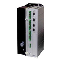
Parker Compax3 Fluid T40 Operating Instructions Manual (398 pages)
Positioning via digital I/Os & Com port
Brand:
Parker
| Category:
Servo Drives
| Size: 20 MB
Table of Contents
Inhalt
5
Table of Contents
5
1 Introduction
13
Device Assignment
13
Scope of Delivery
14
Type Specification Plate
15
Packaging, Transport, Storage
16
Safety Instructions
18
General Hazards
18
Safety-Conscious Working
18
Special Safety Instructions
19
Warranty Conditions
20
Conditions of Utilization
21
Conditions of Utilization for CE-Conform Operation
21
Conditions of Utilization Mains Filter
21
Conditions of Utilization for Cables / Motor Filter
22
Additional Conditions of Utilization
23
Conditions of Utilization for UL Certification Compax3S
24
Conditions of Utilization for UL Certification Compax3M
25
Conditions of Utilization for UL Certification Compax3H
26
Current on the Mains PE (Leakage Current)
27
Supply Networks
27
2 C3I12T11 Function Overview
28
3. Compax3 Device Description
30
3 Compax3 Device Description
30
Meaning of the Status Leds - Compax3 Axis Controller
30
In this Chapter You Can Read About: Meaning of the Status Leds - Compax3 Axis Controller
30
Meaning of the Status Leds - PSUP (Mains Module)
31
Connections of Compax3S
32
Compax3S Connectors
32
Connector and Pin Assignment C3S
33
Control Voltage 24VDC / Enable Connector X4 C3S
35
Motor / Motor Brake (C3S Connector X3)
36
Compax3Sxxx V2
37
Main Voltage Supply C3S Connector X1
37
Braking Resistor / High Voltage DC C3S Connector X2
38
Compax3Sxxx V4
40
Power Supply Connector X1 for 3AC 400VAC/480VAC-C3S Devices
40
Braking Resistor / High Voltage Supply Connector X2 for 3AC 400VAC/480VAC_C3S Devices
41
Connection of the Power Voltage of 2 C3S 3AC Devices
41
Installation Instructions Compax3M
42
Psup/Compax3M Connections
44
Front Connector
44
Connections on the Device Bottom
45
Connections of the Axis Combination
46
Control Voltage 24VDC PSUP (Mains Module)
47
Mains Supply PSUP (Mains Module) X41
48
Braking Resistor / Temperature Switch PSUP (Mains Module)
50
Motor / Motor Brake Compax3M (Axis Controller)
52
Temperature Switch PSUP (Mains Module)
52
Measurement of the Motor Temperature of Compax3M (Axis Controller)
53
Safety Technology Option for Compax3M (Axis Controller)
53
3.6 Connections of Compax3H
54
Connections of Compax3H
54
Compax3H Plugs/Connections
54
Connection of the Power Voltage
55
Compax3H Connections Front Plate
57
Plug and Pin Assignment C3H
57
Motor / Motor Brake C3H
59
Control Voltage 24 VDC C3H
60
Mains Connection Compax3H
60
Braking Resistor / Supply Voltage C3H
61
Connect Braking Resistor C3H
61
Power Supply Voltage DC C3H
61
Connection of the Power Voltage of 2 C3H 3AC Devices
62
Communication Interfaces
63
RS232/RS485 Interface (Plug X10)
63
Communication Compax3M
64
Communication in the Axis Combination (Connector X30, X31)
64
PC - PSUP (Mains Module)
64
Adjusting the Basic Address
65
Setting the Axis Function
65
Signal Interfaces
66
Resolver / Feedback (Plug X13)
66
Analogue / Encoder (Plug X11)
67
Connections of the Encoder Interface
67
Wiring of Analog Interfaces
67
Digital Inputs/Outputs (Plug X12)
68
Connection of the Digital Outputs/Inputs
69
Logic Proximity Switch Types
69
Installation and Dimensions Compax3
70
Mounting and Dimensions Compax3S
70
Mounting and Dimensions Compax3S0Xxv2
70
Mounting and Dimensions Compax3S100V2 and S0Xxv4
71
Mounting and Dimensions Compax3S150V2 and S150V4
72
Mounting and Dimensions Compax3S300V4
73
Mounting and Dimensions PSUP/C3M
74
Mounting and Dimensions PSUP10/C3M050D6, C3M100D6, C3M150D6
74
Mounting and Dimensions PSUP20/PSUP30/C3M300D6
75
With Upper Mounting, the Housing Design May be Different
75
Mounting and Dimensions C3H
76
Mounting Distances, Air Currents Compax3H050V4
77
Mounting Distances, Air Currents Compax3H090V4
77
Mounting Distances, Air Currents Compax3H1Xxv4
78
Safety Function - STO (=Safe Torque Off)
79
General Description
79
Important Terms and Explanations
79
Advantages of Using the "Safe Torque Off" Safety Function
80
Intended Use
80
Devices with the STO (=Safe Torque Off) Safety Function
81
STO (= Safe Torque Off) with Compax3S
82
STO Principle (= Safe Torque Off) with Compax3S
82
Conditions of Utilization STO (=Safe Torque Off) Safety Function
84
Notes on the STO Function
84
STO Application Example (= Safe Torque Off)
86
Technical Characteristics STO Compax3S
89
3.10.3. Sto (= Safe Torque Off) with Compax3M (Option S1)
90
In this Chapter You Can Read About: Safety Switching Circuits
90
STO (= Safe Torque Off) with Compax3M (Option S1)
90
Safety Switching Circuits
90
Conditions of Utilization for the STO Function with Compax3M
91
Safety Notes for the STO Function in the Compax3M
91
STO Delay Times
92
Compax3M STO Application Description
93
STO Function Test
96
Technical Details of the Compax3M S1 Option
98
Parker Eme 4. Setting up Compax3
99
4 Setting up Compax3
99
Configuration
99
Compax3M
100
Test Commissioning of a Compax3 Axis
101
Selection of the Supply Voltage Used
101
Motor Selection
101
In this Chapter You Can Read About: Test Commissioning of a Compax3 Axis
101
Optimize Motor Reference Point and Switching Frequency of the Motor Current
102
Ballast Resistor
105
General Drive
105
Defining the Reference System
106
Measure Reference
106
Parker Eme 4.1.7.2 Machine Zero
109
Machine Zero
109
Positioning after Homing Run
110
Absolute Encoder
111
Operation with Multiturn Emulation
111
Machine Zero Modes Overview
112
Homing Modes with Home Switch (on X12/14)
114
Machine Zero Modes Without Home Switch
120
Adjusting the Machine Zero Proximity Switch
125
Machine Zero Speed and Acceleration
125
Travel Limit Settings
126
Change Assignment Direction Reversal / Limit Switches
129
Change Initiator Logic
129
Defining Jerk / Ramps
130
Jerk Limitation
130
Ramp Upon Error / Deenergize
131
Limit and Monitoring Settings
133
Current (Torque) Limit
133
Positioning Window - Position Reached
133
Following Error Limit
135
Maximum Operating Speed
135
Operating Mode / I/O Assignment
136
I/O Assignment for Control Via the Compax3 Inputs/Outputs
136
I/O Assignment, Control Word and Status Word with Control Via COM Port
137
Encoder Simulation
141
Encoder Bypass with Feedback Module F12 (for Direct Drives)
141
Absolute- /Continuous Mode
141
Position Mode in Reset Operation
142
Examples in the Help File
142
Defining the STOP Function
142
Reg-Related Positioning / Defining Ignore Zone
144
Write into Set Table
145
Dynamic Positioning
145
Programmable Status Bits (Psbs)
146
Moveabs and Moverel
147
Set Selection
147
Reg-Related Positioning (Regsearch, Regmove)
148
Electronic Gearbox (Gearing)
152
Speed Specification (Velocity)
153
Stop Command (Stop)
153
Error Response
153
Configuration Name / Comments
154
Configuring the Signal Source
155
Signal Source of the Load Feedback System
155
Select Signal Source for Gearing
155
Encoder A/B 5V, Step/Direction or SSI Feedback as Signal Source
156
Signal Source HEDA
156
+/-10V Analog Speed Setpoint Value as Signal Source
158
Load Control
160
Configuration of Load Control
162
Error: Position Difference between Load Mounted and Motor Feedback too High
163
Load Control Signal Image
163
Object for the Load Control (Overview)
164
Objects for Load Control
164
Optimization
165
Optimization Window
166
Scope
167
Monitor Information
167
User Interface
168
Example: Setting the Oscilloscope
173
Controller Optimization
175
Introduction
175
4.4.3.2 Configuration
178
Configuration
178
In this Chapter You Can Read About: Control Path
178
Mass Inertia
179
Motor Parameters Relevant for the Control
179
Nominal Point Data
179
Quality of Different Feedback Systems
181
Saturation Values
181
Typical Problems of a Non Optimized Control
182
Feedback Error Compensation
183
Commutation Settings
184
I²T - Monitoring of the Motor
184
Relevant Application Parameters
187
Parker Eme
191
Asynchronous Motors
191
In this Chapter You Can Read About: Type Specification Plate Data
191
Replacement Switching Diagram - Data for a Phase
192
Slip Frequency
192
Cut-Off Frequency for the Field Weakening Range
193
Saturation Behavior
193
Asynchronous Motors: Extension of the Controller Structure
194
Automatic Controller Design
195
Determination of the Commutation Settings
194
Rotor Time Constant
194
Parker Eme 4.4.3.4 Setup and Optimization of the Control
207
Setup and Optimization of the Control
207
Standard
208
Advanced
214
Commissioning Window
229
Proceeding During Controller Optimization
231
Signal Filtering with External Command Value
240
Signal Filtering for External Setpoint Specification and Electronic Gearbox
240
Signal Filtering for External Setpoint Specification and Electronic Cam
241
Input Simulation
242
Calling up the Input Simulation
242
Operating Principle
243
Setup Mode
244
Motion Objects in Compax3
245
Load Identification
246
Boundary Conditions
246
Principle
246
Process of the Automatic Determination of the Load Characteristic Value (Load Identification)
247
Tips
248
Alignment of the Analog Inputs
249
Gain Alignment
249
Offset Alignment
249
Signal Processing of the Analog Inputs
250
Parker Eme 4.4.9. C3 Servosignalanalyzer
251
C3 Servosignalanalyzer
251
Servosignalanalyzer - Function Range
251
Signal Analysis Overview
252
Installation Enable of the Servosignalanalyzer
253
Analyses in the Time Range
255
Measurement of Frequency Spectra
258
Measurement of Frequency Responses
261
4.4.9.7 Overview of the User Interface
268
In this Chapter You Can Read About: Selection of the Signal or System to be Measured
268
Overview of the User Interface
268
Mechanical System
270
Position Control
271
Frequency Settings
273
Speed Control
273
Other Settings
275
Operating and Status Field
277
Display of the Measurement Result
279
Display of the Measurement Point at the Cursor Position
280
Basics of Frequency Response Measurement
281
In this Chapter You Can Read about
281
Examples Are Available as a Movie in the Help File
286
Profileviewer for the Optimization of the Motion Profile
287
Input Values
287
Mode 1: Time and Maximum Values Are Deduced from Compax3
287
Mode 2: Compax3 Input Values Are Deduced from Times and Maximum Values
288
Turning the Motor Holding Brake on and off
289
5. Control Via Rs232 / Rs485 / Usb
290
5 Control Via RS232 / RS485 / USB
290
Status Diagram
291
I/O Assignment, Control Word and Status Word with Control Via COM Port
292
I/O Assignment
292
Control Word
294
Status Word 1 & 2
295
Examples Include: Control Via COM Port
296
Layout of the Set Table
299
Assignment of the Different Motion Functions
299
General Layout of the Table
299
Definition of the States of the Programmable Status Bits (Psbs)
300
Compax3 Communication Variants
300
Compa3 Communication Variants
300
PC <-> Compax3 (RS232)
301
PC <-> Compax3 (RS485)
303
PC <-> C3M Device Combination (USB)
304
USB-RS485 Moxa Uport 1130 Adapter
305
ETHERNET-RS485 Netcom 113 Adapter
306
Modem MB-Connectline MDH 500 / MDH 504
307
C3 Settings for RS485 Two Wire Operation
308
C3 Settings for RS485 Four Wire Operation
309
COM Port Protocol
310
RS485 Settings Values
310
ASCII - Record
311
Binary Record
312
Remote Diagnosis Via Modem
315
Structure
316
Configuration of Local Modem 1
317
Configuration of Remote Modem 2
317
Recommendations for Preparing the Modem Operation
318
6 Compax3 - Objects
319
Object Overview I12 T11
319
Detailed Object List
322
7 Status Values
323
D/A-Monitor
323
8 Error
324
Error List
324
9 Order Code
325
Order Code Device: Compax3
325
Order Code for Mains Module: PSUP
326
Order Code for Accessories
326
10 Compax3 Accessories
330
Parker Servo Motors
330
Direct Drives
330
Transmitter Systems for Direct Drives
331
Linear Motors
332
Rotary Servo Motors
332
Torque Motors
332
EMC Measures
333
Mains Filter
333
Mains Filter NFI01/01
334
Mains Filter NFI01/02
334
Mains Filter for NFI01/03
335
Mains Filter Nfi02/0X
335
Mains Filter NFI03/01& NFI03/03
336
Mains Filter NFI03/02
337
Motor Output Filter
338
Motor Output Filter MDR01/01
338
Motor Output Filter MDR01/04
338
Motor Output Filter MDR01/02
339
Wiring of the Motor Output Filter
339
Mains Filter for PSUP30
340
Mains Filters
340
Connections to the Motor
341
Resolver Cable
342
Sincos© Cable
343
Endat Cable
344
Motor Cable
344
Connection of Terminal Box MH145 & MH205
345
Encoder Cable
346
External Braking Resistors
347
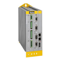
Parker Compax3 Fluid T40 Installation Manual (44 pages)
Single-Axis Servo Drive/Controller/Single axis devices
Brand:
Parker
| Category:
Controller
| Size: 1 MB
Table of Contents
1 Notes on the Documents Supplied
3
C3 Servomanager
4
Table of Contents
6
In this Chapter You Can Read About: Device Assignment
7
Type Specification Plate
8
Packaging, Transport, Storage
9
Safety Instructions
10
General Hazards
10
Safety-Conscious Working
10
Special Safety Instructions
11
Warranty Conditions
12
Conditions of Utilization
13
Conditions of Utilization for CE-Conform Operation
13
Conditions of Utilization for UL Certification Compax3S
15
Current on the Mains PE (Leakage Current)
17
Supply Networks
18
Manufacturer's Declaration of Conformity
19
2 Introduction
7
Device Assignment
7
3 Compax3 Device Description
20
State of Delivery
20
Meaning of the Status Leds - Compax3 Axis Controller
20
Connections of Compax3S
21
Compax3S Connectors
21
Connector and Pin Assignment C3S
22
Control Voltage 24VDC / Enable Connector X4 C3S
24
Motor / Motor Brake (C3S Connector X3)
25
C3Sxxx V2
26
C3Sxxx V4
29
Signal Interfaces
31
RS232 / RS485 Interface (Plug X10)
31
Resolver / Feedback (Connector X13)
32
Analog / Encoder (Plug X11)
33
Digital Inputs/Outputs (Plug X12)
34
Installation and Dimensions Compax3
35
Mounting and Dimensions Compax3S0Xxv2
35
In this Chapter You Can Read About: Mounting and Dimensions Compax3S0Xxv2
35
Monting and Dimensions Compax3S100V2 and S0Xxv4
36
Mounting and Dimensions Compax3S150V2 and S150V4
37
Monting and Dimensions Compax3S150V2 and S150V4
37
Mounting and Dimensions Compax3S300V4
38
4 Specifications
39
5 Index
44
Advertisement
Parker Compax3 Fluid T40 Start-Up (40 pages)
Startup of a motor without motor load
Brand:
Parker
| Category:
Servo Drives
| Size: 3 MB
Table of Contents
English
3
Table of Contents
3
You Can Read about the Following in this Chapter
4
Aim of this Manual
4
Task: Setting up Compax3 , Moving the Motor
4
Components Required
4
Preparation
5
Installation of the C3 Servomanager
5
Required Wirings
6
Configuring Compax3
8
Set Interface PC - Compax3
8
Set Compax3 Device Type
8
Configuration Sequence
9
Download Configuration
11
Setting up Compax3
12
Commissioning
14
Define Test Motion Parameters
15
Execute Test Movements
17
Start up
21
Deutsch
23
In diesem Kapitel Finden Sie
24
Ziel dieser Anleitung
24
Aufgabe: Compax3 Inbetriebnehmen, Motor Bewegen
24
Erforderliche Komponenten
24
Vorbereitung
25
Installation des C3 Servomanagers
25
Notwendige Verdrahtungen
26
Compax3 Konfigurieren
28
Schnittstelle PC - Compax3 Einstellen
28
Compax3 Gerätetyp Einstellen
28
Konfigurationsablauf
29
Download Konfiguration
31
1 Start up
32
Compax3 Inbetriebnehmen
32
Inbetriebnahme
34
Testbewegungs - Parameter Festlegen
35
Testbewegungen Ausführen
37
Darstellung der Werte auf Oszi und in der Statusanzeige
39
2 Index
40
Parker Compax3 Fluid T40 Installation Manual (28 pages)
Hydraulics Controller
Brand:
Parker
| Category:
Controller
| Size: 0 MB
Table of Contents
Notes on the Documents Supplied
3
C3 Servomanager
4
Table of Contents
6
Introduction
7
Device Assignment Compax3 Fluid
7
Type Specification Plate Compax3 Fluid
8
Packaging, Transport, Storage
9
Safety Instructions
10
General Hazards
10
Safety-Conscious Working
10
Special Safety Instructions
11
Warranty Conditions
11
Conditions of Utilization for CE-Conform Operation
12
Compax3F Device Description
13
State of Delivery
13
Plug and Connector Assignment Compax3 Fluid
13
Meaning of the Front Panel Leds (Via X10)
13
In this Chapter You Can Read about
13
In this Chapter You Can Read About: Meaning of the Front Panel Leds (Via X10)
13
Plug and Connector Assignment
14
Plug and Connector Assignment Complete
15
Analog Input (Plug X1)
16
Wiring of the Analog Inputs
16
Analog Output (Plug X2)
17
Wiring of Analog Outputs
17
Voltage Supply (Plug X3)
18
RS232 / RS485 Interface (Plug X10)
19
Analog / Encoder (Plug X11)
20
Connections of the Encoder Interface
20
Digital Inputs/Outputs (Plug X12)
21
Connection of the Digital Outputs/Inputs
21
Feedback (Connector X13)
22
Connections of the Encoder Interface
22
Mounting and Dimensions
23
Specifications
24
Index
28
Parker Compax3 Fluid T40 Installation Manual (28 pages)
Hydraulics Controller
Brand:
Parker
| Category:
Controller
| Size: 1 MB
Table of Contents
Notes on the Documents Supplied
3
C3 Servomanager
4
Table of Contents
5
Introduction
6
Device Assignment Compax3 Fluid
6
Scope of Delivery
6
In diesem Kapitel Finden Sie Device Assignment Compax3 Fluid
6
Type Specification Plate Compax3 Fluid
7
Packaging, Transport, Storage
8
Safety Instructions
9
General Hazards
9
Safety-Conscious Working
9
Special Safety Instructions
9
Warranty Conditions
10
Conditions of Utilization for CE-Conform Operation
11
EC Declaration of Conformity Compax3F
12
Compax3F Device Description
13
State of Delivery
13
Plug and Connector Assignment Compax3 Fluid
13
Meaning of the Front Panel Leds (Via X10)
13
In diesem Kapitel Finden Sie
13
In diesem Kapitel Finden Sie Meaning of the Front Panel Leds (Via X10)
13
Plug and Connector Assignment
14
Plug and Connector Assignment Complete
15
Analog Input (Plug X1)
16
Analog Output (Plug X2)
17
Voltage Supply (Plug X3)
18
RS232/RS485 Interface (Plug X10)
19
Analog / Encoder (Plug X11)
20
Digital Inputs/Outputs (Plug X12)
21
Feedback (Connector X13)
22
Mounting and Dimensions
23
Technical Characteristics
24
Index
26
Advertisement
Related Products
Parker Compax3S
Parker Compax3S025V2
Parker Compax3S063V2
Parker Compax3S100V2
Parker Compax3S150V2
Parker Compax3S015V4
Parker Compax3S038V4
Parker Compax3S075V4
Parker Compax3S150V4
Parker Compax3H050V4
Parker Categories
Controller
Control Unit
Industrial Equipment
Water Filtration Systems
DC Drives
More Parker Manuals
Login
Sign In
OR
Sign in with Facebook
Sign in with Google
Upload manual
Upload from disk
Upload from URL