Parker Compax3 Series Operating Instructions Manual
Electromechanical automation, positioning via devicenet
Hide thumbs
Also See for Compax3 Series:
- Operating instructions manual (150 pages) ,
- Installation manual (60 pages)
Table of Contents
Advertisement
Quick Links
Compax3
Electromechanical Automation
Operating instructions Compax3 I22T11
Positioning via DeviceNet
192-120114 N5 C3I22T11
June 2008
Release R08-0
We reserve the right to make technical changes.
19.06.08 13:24
192-120114 N5 C3I22T11 June 2008
The data correspond to the current status at the time of printing.
Advertisement
Chapters
Table of Contents

Related Manuals for Parker Compax3 Series


Summary of Contents for Parker Compax3 Series
- Page 1 Compax3 Electromechanical Automation Operating instructions Compax3 I22T11 Positioning via DeviceNet 192-120114 N5 C3I22T11 June 2008 Release R08-0 We reserve the right to make technical changes. 19.06.08 13:24 192-120114 N5 C3I22T11 June 2008 The data correspond to the current status at the time of printing.
- Page 2 Reg. Nr. 36 38 E-mail: sales.automation@parker.com mailto:sales.automation@parker.com Parker Hannifin GmbH & Co. KG - registered office: Bielefeld - Amtsgericht: Bielefeld HRA 14808 Personally liable shareholder: Parker Hannifin Management GmbH - Amtsgericht: Bielefeld HRB 35489 executive board: Dr. Gerd Scheffel, Günter Schrank, Christian Stein, Kees Veraart, Hans Wolfs - Chairman of the board: Hansgeorg...
-
Page 3: Table Of Contents
Parker EME Introduction Contents 1. Introduction.....................10 Device assignment ................10 Type specification plate ................ 11 Packaging, transport, storage .............. 12 Safety Instructions................. 13 1.4.1. General hazards....................13 1.4.2. Safety-conscious working .................. 13 1.4.3. Special safety instructions ................. 14 Warranty conditions ................15 Conditions of utilization ................ - Page 4 Introduction C3I22T11 3.5.6. Mains supply Compax3MP (mains module)............45 3.5.7. Braking resistor / temperature switch Compax3MP (mains module) .... 47 3.5.7.1 Temperature switch Compax3MP (mains module) ........48 3.5.8. Motor / motor brake Compax3M (axis controller) ..........48 3.5.8.1 Measurement of the motor temperature of Compax3M (axis controller) ....................
- Page 5 Parker EME Introduction 3.10.3. Safety instructions for the ”safety torque off” function........80 3.10.4. Application example for ”safe standstill” ............81 3.10.4.1 Safe standstill with bus option ..............81 3.11 Compax3M with safety option S1: Safe torque off......87 3.11.1.
- Page 6 Introduction C3I22T11 4.1.12. Position mode in reset operation............... 141 4.1.12.1 Examples in the help file ................142 4.1.13. Reg-related positioning / defining ignore zone ..........143 4.1.14. Write into set table....................144 4.1.14.1 Programmable status bits (PSBs)............. 144 4.1.15. Motion functions....................145 4.1.15.1 MoveAbs and MoveRel................
- Page 7 Parker EME Introduction 4.3.9.4 Analyses in the time range ............... 252 4.3.9.5 Measurement of frequency spectra ............255 4.3.9.6 Measurement of frequency responses ............. 258 4.3.9.7 Overview of the user interface ..............265 4.3.9.8 Basics of frequency response measurement ........... 279 4.3.9.9...
- Page 8 Order code device: Compax3 ............. 341 Order code for mains module: Compax3MP ........342 Accessories order code ..............342 9. Compax3 Accessories .................346 Parker servo motors ................346 9.1.1. Direct drives ......................346 9.1.1.1 Feedback systems for direct drives ............347 9.1.1.2...
- Page 9 Parker EME Introduction 9.4.1.2 Permissible braking pulse power: BRM08/01 with C3S015V4 / C3S038V4....................366 9.4.1.3 Permissible braking pulse power: BRM08/01 with C3S025V2 ....366 9.4.1.4 Permissible braking pulse power: BRM09/01 with C3S100V2 ....367 9.4.1.5 Permissible braking pulse power: BRM10/01 with C3S150V4 ....367 9.4.1.6...
-
Page 10: Introduction
Introduction C3I22T11 1. Introduction In this chapter you can read about: Device assignment ......................10 Type specification plate......................11 Packaging, transport, storage ....................12 Safety Instructions ......................13 Warranty conditions......................15 Conditions of utilization ......................16 Device assignment This manual applies to the following devices: Compax3S025V2 + supplement Compax3S063V2 + supplement Compax3S100V2 + supplement Compax3S150V2 + supplement... -
Page 11: Type Specification Plate
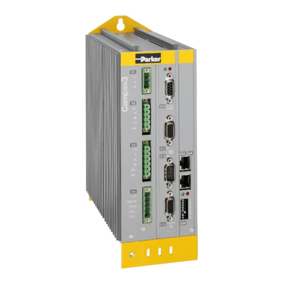
Parker EME Introduction Type specification plate You will find the exact description of the device on the type specification plate, which can be found on the device: Compax3 - Type specification plate: Explanation: Type designation The complete order designation of the device (2, 5, 6, 9, 8). -
Page 12: Packaging, Transport, Storage
Introduction C3I22T11 Packaging, transport, storage Packaging material and transport Caution! The packaging material is inflammable, if it is disposed of improperly by burning, lethal fumes may develop. The packaging material must be kept and reused in the case of a return shipment. Improper or faulty packaging may lead to transport damages. -
Page 13: Safety Instructions
Parker EME Introduction Safety Instructions In this chapter you can read about: General hazards .........................13 Safety-conscious working....................13 Special safety instructions ....................14 1.4.1. General hazards General Hazards on Non-Compliance with the Safety Instructions The device described in this manual is designed in accordance with the latest technology and is safe in operation. -
Page 14: Special Safety Instructions
Introduction C3I22T11 1.4.3. Special safety instructions Check the correct association of the device and its documentation. Never detach electrical connections while voltage is applied to them. Safety devices must be provided to prevent human contact with moving or rota- ting parts. Make sure that the device is operated only when it is in perfect condition. -
Page 15: Warranty Conditions
Parker EME Introduction Warranty conditions The device must not be opened. Do not make any modifications to the device, except for those described in the manual. Make connections to the inputs, outputs and interfaces only in the manner des- cribed in the manual. -
Page 16: Conditions Of Utilization
Introduction C3I22T11 Conditions of utilization In this chapter you can read about: Conditions of utilization for CE-conform operation .............16 Conditions of utilization for UL certification Compax3S............19 Conditions of utilization for UL certification Compax3M .............21 Current on the mains PE (leakage current) ................22 Supply networks .........................23 1.6.1. - Page 17 Parker EME Introduction Connection length: Connection between mains filter and device: unshielded: < 0.5m shielded: < 5m (fully shielded on ground – e.g. ground of control cabinet) Motor and Feedback Operation of the devices only with motor and feedback cables whose plugs cable: contain a special full surface area screening.
- Page 18 Signal leads should never pass close to excessive sources of interference (motors, transformers, contactors etc.). Accessories: Make sure to use only the accessories recommended by Parker Connect all cable shields at both ends, ensuring large contact areas! Warning: This is a product in the restricted sales distribution class according to EN 61800-3.
-
Page 19: Conditions Of Utilization For Ul Certification Compax3S
Parker EME Introduction 1.6.2. Conditions of utilization for UL certification Compax3S UL certifiction for Compax3S conform to UL: according to UL508C Certified E-File_No.: E235 342 The UL certification is documented by a ”UL” logo on the devi- ce (type specification plate). - Page 20 Introduction C3I22T11 Fuses In addition to the main fuse, the devices must be equipped with a S 201 K or S 203 K fuse made by ABB. C3S025V2: ABB, nominal 480V 10A, 6kA C3S063V2: ABB, nominal 480V, 16A, 6kA C3S100V2: ABB, nominal 480V, 16A, 6kA C3S150V2: ABB, nominal 480V, 20A, 6kA C3S015V4: ABB, nominal 480V, 6A, 6kA C3S038V4: ABB, nominal 480V, 10A, 6kA...
-
Page 21: Conditions Of Utilization For Ul Certification Compax3M
Parker EME Introduction 1.6.3. Conditions of utilization for UL certification Compax3M UL certifiction for Compax3M conform to UL: according to UL508C Certified E-File_No.: E235 342 The UL certification is documented by a ”UL” logo on the device (type specification plate). -
Page 22: Current On The Mains Pe (Leakage Current)
Introduction C3I22T11 1.6.4. Current on the mains PE (leakage current) This product can cause a direct current in the protective lead. If a residual current device (RCD) is used for protection in the event of direct or indirect contact, only a type B (all current sensitive) RCD is permitted on the current supply side of this product . -
Page 23: Supply Networks
Parker EME Introduction 1.6.5. Supply networks The Compax3 servo controller series is designed for fixed connection to TN net- works (TN-C, TN-C-S or TN-S). Please note that the line-earth voltage may not exceed 300VAC. When grounding the neutral conductor, mains vol- tages of up to 480VAC are permitted. -
Page 24: Compax3 Xxxx I22T11 Introduction
Compax3 Xxxx I22T11 Introduction C3I22T11 2. Compax3 Xxxx I22T11 Introduction Due to its high functionality, the Positioning version of Compax3 forms an ideal basis for many applications in high-performance motion automation. Up to 31 motion profiles with the motion functions: Absolute or relative positioning, electronic gearing register-related positioning,... - Page 25 Parker EME Compax3 Xxxx I22T11 Introduction DeviceNet characteristic data DeviceNet Predefined Master/Slave Connection Set Standard 2.0 Group-2-Slave Fieldbus I/O Data or Process Data (Pol- led, COS/Cyclic I/O and Bit Strobe) Implemented object classes Identify, Message Router, DeviceNet, Assembly, Connection, Acknowledge...
-
Page 26: Compax3 Device Description
Compax3 device description C3I22T11 3. Compax3 device description In this chapter you can read about: Meaning of the status LEDs - Compax3 axis controller .............26 Meaning of the status LEDs - Compax3MP (mains module) ..........27 Connections of Compax3S....................28 Installation instructions Compax3M..................38 Compax3MP/Compax3M connections ................40 Connections of Compax3H ....................50 Communication interfaces ....................60... -
Page 27: Meaning Of The Status Leds - Compax3Mp (Mains Module)
Parker EME Compax3 device description Meaning of the status LEDs - Compax3MP (mains module) C3MP Status LEDs Left LED (green) Right LED (red) Control voltage 24 VDC iss missing** Error of mains module* DC power voltage is built up Flashes quickly... -
Page 28: Connections Of Compax3S
Compax3 device description C3I22T11 Connections of Compax3S In this chapter you can read about: Compax3S connectors .......................28 Connector and pin assignment C3S...................29 Control voltage 24VDC / enable connector X4 C3S............31 Motor / Motor brake (C3S connector X3) ................32 C3Sxxx V2..........................33 C3Sxxx V4..........................36 3.3.1. -
Page 29: Connector And Pin Assignment C3S
Parker EME Compax3 device description Always switch devices off before wiring them! Dangerous voltages are still present until 5 minutes after switching off the power supply! Caution! When the control voltage is missing there is no indication whether or not high voltage supply is available. - Page 30 Compax3 device description C3I22T11 In detail: The fitting of the different plugs depends on the extension level of Compax3. In part, the assignment depends on the Compax3 option implemented. Compax3 1AC X20/1 X10/1 X10/1 X10/1 Power supply RS485 +5V RS485 +5V EnableRS232 0V X20/2 X10/2...
-
Page 31: Control Voltage 24Vdc / Enable Connector X4 C3S
Parker EME Compax3 device description 3.3.3. Control voltage 24VDC / enable connector X4 C3S Description Line cross sections: +24V (supply) minimum: 0.25mm Gnd24 V maximum: 2.5mm Enable_in (AWG: 24 ... 12) Enable_out_a Enable_out_b Control voltage 24VDC Compax3S and Compax3H Controller type... -
Page 32: Motor / Motor Brake (C3S Connector X3)
Compax3 device description C3I22T11 3.3.4. Motor / Motor brake (C3S connector X3) Designation U (motor) V (motor) W (motor) PE (motor) Motor holding brake * Motor holding brake * * Please note that Compax3 will report error "open circuit at holding brake" (5481h / 2163d) if the current is <... -
Page 33: C3Sxxx V2
Parker EME Compax3 device description 3.3.5. C3Sxxx V2 In this chapter you can read about: Main voltage supply C3S connector X1 ................33 Braking resistor / high voltage DC C3S connector X2............34 3.3.5.1 Main voltage supply C3S connector X1 In this chapter you can read about: Power supply plug X1 for 1 AC 230VAC/240VAC devices.......... -
Page 34: Braking Resistor / High Voltage Dc C3S Connector X2
Compax3 device description C3I22T11 Mains connection Compax3S1xxV2 3AC Controller type S100V2 S150V2 Supply voltage Three phase 3* 230VAC/240VAC 80-253 VAC/50-60Hz Input current 10Aeff 13Aeff Maximum fuse rating per device 16 A (MCB miniature 20 A (MCB miniature (=short circuit rating) circuit breaker) circuit breaker) Caution! - Page 35 Parker EME Compax3 device description Braking resistor / high voltage supply plug X2 for 3AC 230VAC/240VAC devices Description + Braking resistor no short-circuit protection! - Braking resistor + DC high voltage supply - DC high voltage supply Braking operation Compax3S1xxV2 3AC...
-
Page 36: C3Sxxx V4
Compax3 device description C3I22T11 3.3.6. C3Sxxx V4 In this chapter you can read about: Power supply connector X1 for 3AC 400VAC/480VAC-C3S devices ........36 Braking resistor / high voltage supply connector X2 for 3AC 400VAC/480VAC_C3S devices ............................37 Connection of the power voltage of 2 C3S 3AC devices............38 3.3.6.1 Power supply connector X1 for 3AC 400VAC/480VAC-C3S devices... -
Page 37: Braking Resistor / High Voltage Supply Connector X2 For 3Ac 400Vac/480Vac_C3S Devices
Parker EME Compax3 device description 3.3.6.2 Braking resistor / high voltage supply connector X2 for 3AC 400VAC/480VAC_C3S devices Description + Braking resistor no short-circuit protec- tion! - Braking resistor + DC high voltage supply - DC high voltage supply Braking operation Compax3SxxxV4 3AC... -
Page 38: Connection Of The Power Voltage Of 2 C3S 3Ac Devices
Compax3 device description C3I22T11 3.3.6.3 Connection of the power voltage of 2 C3S 3AC devices Caution! The power voltage DC of the single phase Compax3 servo axes must not be connected! In order to improve the conditions during brake operation, the DC power voltage of 2 servo axes may be connected. - Page 39 Parker EME Compax3 device description Required tools: Allen key M5 for fixing the devices in the control cabinet. Crosstip screwdriver M4 for connection rails of the DC rail modules. Crosstip screwdriver M5 for grounding screw of the device. Flat-bladed screwdriver 0.4x2.5 / 0.6x3.5 / 1.0x4.0 for wiring and mounting of the phenix clamps.
-
Page 40: Compax3Mp/Compax3M Connections
Compax3 device description C3I22T11 Compax3MP/Compax3M connections In this chapter you can read about: Front connector ........................40 Connections on the device bottom ..................41 Connections of the axis combination..................42 Connector and pin assignment...................43 Control voltage 24VDC Compax3MP (mains module) ............45 Mains supply Compax3MP (mains module)...............45 Braking resistor / temperature switch Compax3MP (mains module) .........47 Motor / motor brake Compax3M (axis controller) ...............48 3.5.1. -
Page 41: Connections On The Device Bottom
Parker EME Compax3 device description 3.5.2. Connections on the device bottom Always switch devices off before wiring them! Dangerous voltages are still present until 5 minutes after switching off the power supply! Caution! When the control voltage is missing there is no indication whether or not high voltage supply is available. -
Page 42: Connections Of The Axis Combination
Compax3 device description C3I22T11 3.5.3. Connections of the axis combination The Compax3M axis controllers are connected to the supply voltages via rails. Supply voltage 24VDC DC power voltage supply The rails are located behind the yellow protective covers. In order to connect the rails of the devices, you may have to remove the yellow plastic device inserted at the side. -
Page 43: Connector And Pin Assignment
Parker EME Compax3 device description 24VDC Gnd 24 V -HV DC +HV DC Note: External components may not be connected to the rail system. Protective covers The user is responsible for protective covers and/or additional safety measures in order to prevent damages to persons and electric accidents. - Page 44 Compax3 device description C3I22T11 In detail: The fitting of the different plugs depends on the extension level of Compax3. In part, the assignment depends on the Compax3 option implemented. Compax3MP Compax3M X20/1 Communication Bus Communication Bus X20/2 X20/3 X11/1 X20/4 Output+24V res.
-
Page 45: Control Voltage 24Vdc Compax3Mp (Mains Module)
Parker EME Compax3 device description 3.5.5. Control voltage 24VDC Compax3MP (mains module) connector X9 Designation Line cross sections: minimum: 0.5mm with contactor sleeve +24V maximum: 6mm with contactor sleeve Gnd 24 V (AWG: 20 ... 10) Control voltage 24VDC Compax3MP / Compax3M... - Page 46 Compax3 device description C3I22T11 Mains connection Compax3MP10D6 Device type Compax3MP10 230V 400V 480V Supply voltage 230VAC ±10% 400VAC ±10% 480VAC ±10% 50-60Hz 50-60Hz 50-60Hz Rated voltage 3AC 230V 3AC 400V 3AC 480V Input current 22Aeff 22Aeff 18Arms Output voltage 325VDC ±10% 565VDC ±10% 680VDC ±10% Output power...
-
Page 47: Braking Resistor / Temperature Switch Compax3Mp (Mains Module)
Parker EME Compax3 device description 3.5.7. Braking resistor / temperature switch Compax3MP (mains module) The energy generated during braking operation must be dissipated via a braking resistor. Connector X40 Description + Braking resistor no short-circuit protec- tion! - Braking resistor... -
Page 48: Temperature Switch Compax3Mp (Mains Module)
Compax3 device description C3I22T11 3.5.7.1 Temperature switch Compax3MP (mains module) Connector X40 Pin T1R, T2R Temperature monitoring: The temperature switch (normally closed contact) must be connected, unless an error message will be issued. Temperature switch/relay No galvanic separation, the temperature sensor (normally closed contact) must comply with the safe separation according to EN 60664. -
Page 49: Measurement Of The Motor Temperature Of Compax3M (Axis Controller)
Parker EME Compax3 device description Requirements for <80m per axis (the cable must not be rolled up! Compax3M motor The entire length of the motor cable per axis combination may not exceed 300m. cable A motor output filter (see page 353) is required for motor cables >20m : MDR01/04 (max. -
Page 50: Connections Of Compax3H
Compax3 device description C3I22T11 Connections of Compax3H In this chapter you can read about: Compax3H plugs/connections....................50 Terminal clamps – max. line cross section C3H ..............52 Plug and pin assignment C3H ....................53 Motor / Motor brake C3H ....................55 Control voltage 24 VDC C3H....................56 Mains connection Compax3H.....................57 Braking resistor / supply voltage C3H ................57 3.6.1. - Page 51 Parker EME Compax3 device description Controller front plate LED2 LED3 LED1 Motor brake HEDA in (Option) 24VDC HEDA out (Option) RS232/RS485 with jumper to the Inputs Outputs (Option M10/12) programming interface Analog/Encoder Bus (Option) connector type de- pends on the bus...
-
Page 52: Terminal Clamps - Max. Line Cross Section C3H
Compax3 device description C3I22T11 3.6.2. Terminal clamps – max. line cross section C3H Terminal clamps – max. line cross section The line cross sections must correspond to the locally valid safety regulations. The local regulations have always priority. Power clamps Control lines (minimum/maximum section) C3H050V4... -
Page 53: Plug And Pin Assignment C3H
Parker EME Compax3 device description 3.6.3. Plug and pin assignment C3H Overview Compax3 AC - Versorgung AC - Supply RS232 DC - Versorgung X4 (24VDC) DC - Supply SSK1 Further information on the assignment of the plug mounted at the particular... - Page 54 Compax3 device description C3I22T11 In detail: The fitting of the different plugs depends on the extension level of Compax3. In part, the assignment depends on the Compax3 option implemented. X20/1 X10/1 X10/1 X10/1 RS485 +5V RS485 +5V EnableRS232 0V X20/2 X10/2 X10/2 X10/2...
-
Page 55: Motor / Motor Brake C3H
Parker EME Compax3 device description 3.6.4. Motor / Motor brake C3H Motor connection clamps Designation M1/U U (motor) M2/V V (motor) M3/W W (motor) PE (motor) Requirements for A motor output filter is required for motor cables >50m. Please contact us. -
Page 56: Control Voltage 24 Vdc C3H
Compax3 device description C3I22T11 3.6.5. Control voltage 24 VDC C3H Connector Description X4 Pin Gnd 24 V +24V 24 VDC (power supply) Control voltage 24VDC Compax3S and Compax3H Controller type Compax3 Voltage range 21 - 27VDC Mains module with switch-on current limitation, due to capaci- tive load Fuse MCB miniature circuit breaker or "delayed ac-... -
Page 57: Mains Connection Compax3H
Parker EME Compax3 device description 3.6.6. Mains connection Compax3H Device protection Avoid permanent switching on and off so that the charging connection is not overloaded. Mains connection Compax3HxxxV4 Controller type H050V4 H090V4 H125V4 H155V4 Supply voltage Three phase 3*400VAC/480VAC 350-528VAC / 50-60Hz... -
Page 58: Connect Braking Resistor C3H
Compax3 device description C3I22T11 3.6.7.1 Connect braking resistor C3H Connecting the braking resistor: Designation DBR+ + Braking resistor DBR- - Braking resistor Braking operation of Compax3HxxxV4 Controller type H050V4 H090V4 H125V4 H155V4 Capacitance / storable 2600μF / 3150μF / 5000μF / 5000μF / energy 602Ws... -
Page 59: Connection Of The Power Voltage Of 2 C3H 3Ac Devices
Parker EME Compax3 device description 3.6.7.3 Connection of the power voltage of 2 C3H 3AC devices In order to improve the conditions during brake operation, the DC power voltage of 2 servo axes may be connected. The capacity as well as the storable energy are increased; furthermore the braking energy of one servo axis may be utilized by a second servo axis, depending on the application. -
Page 60: Communication Interfaces
Compax3 device description C3I22T11 Communication interfaces In this chapter you can read about: RS232 / RS485 interface (plug X10) ..................60 Communikation Compax3M ....................61 DeviceNet connector X23 ....................63 3.7.1. RS232 / RS485 interface (plug X10) Interface selectable by contact functions assignment of X10/1: X10/1=0V RS232 X10/1=5V RS485 RS232 (Sub D) -
Page 61: Communikation Compax3M
Parker EME Compax3 device description 3.7.2. Communikation Compax3M In this chapter you can read about: PC - Compax3MP (mains module)..................61 Communication in the axis combination (connector X30, X31)..........61 Adjusting the basic address ....................62 Setting the axis function .....................62 3.7.2.1 PC - Compax3MP (mains module) Connector X3 USB2.0... -
Page 62: Adjusting The Basic Address
Compax3 device description C3I22T11 3.7.2.3 Adjusting the basic address On the mains module, the basic address of the device combination is set in steps of 16 with the aid of the first three dip switches. The mains module contains the set basic address while the axes placed at the right in the combination contain the following addresses. -
Page 63: Devicenet Connector X23
Parker EME Compax3 device description 3.7.3. DeviceNet connector X23 Pin X23 DeviceNet (Open Plug Phoenix MSTB 2.5/5-GF5.08 ABGY AU) Mass CAN- CAN Low Shield Shield CAN+ CAN High not required, internal supply A mating plug is included in the delivery. -
Page 64: Function Of The Bus Leds
Compax3 device description C3I22T11 3.7.3.2 Function of the Bus LEDs LED (red) No. Signal Status Description No Error The bus is operating Single flash Warning at least one of the error counters of the CAN controller has reached the warning level. Double flash Error Communication Fault... -
Page 65: Signal Interfaces
Parker EME Compax3 device description Signal interfaces In this chapter you can read about: Resolver / Feedback (connector X13) ................65 Analog / Encoder (plug X11) ....................66 Digital inputs/outputs (plug X12) ..................67 3.8.1. Resolver / Feedback (connector X13) PIN X13 Feedback /X13 High Density /Sub D... -
Page 66: Analog / Encoder (Plug X11)
Compax3 device description C3I22T11 3.8.2. Analog / Encoder (plug X11) Reference High Density Sub D Encoder +24V (output) max. 70mA Ain1 -: analog input - (14Bit; max. +/-10V) D/A monitor channel 1 (±10V, 8-bit resolution) D/A monitor channel 0 (±10V, 8-bit resolution) +5V (output for encoder) max. -
Page 67: Digital Inputs/Outputs (Plug X12)
Parker EME Compax3 device description 3.8.3. Digital inputs/outputs (plug X12) Input/output High density/Sub D +24VDC output (max. 400mA) No Error Position / speed / gear synchronization Only for "fixed as- attained (max. 100mA) signment" No power output stage current (max. -
Page 68: Connection Of The Digital Outputs/Inputs
Compax3 device description C3I22T11 3.8.3.1 Connection of the digital Outputs/Inputs Wiring of digital outputs Status of digital inputs Compax3 Compax3 SPS/PLC SPS/ X12/1 X12/1 X12/11 100K Ω 22K Ω X12/6 X12/2 22K Ω 10nF 10K Ω Ω 18.2K Ω X12/15 X12/15 The circuit example is valid for all digital outputs! The circuit example is valid for all digital inputs! -
Page 69: Installation And Dimensions Compax3
Parker EME Compax3 device description Installation and dimensions Compax3 In this chapter you can read about: Mounting and dimensions Compax3S................69 Mounting and dimensions C3MP/C3M ................73 Mounting and dimensions C3H ..................75 3.9.1. Mounting and dimensions Compax3S In this chapter you can read about: Mounting and dimensions Compax3S0xxV2..............69... -
Page 70: Monting And Dimensions Compax3S100V2 And S0Xxv4
Compax3 device description C3I22T11 3.9.1.2 Monting and dimensions Compax3S100V2 and S0xxV4 Mounting: 3 socket head screws M5 C3S015V4: C3S038V4: C3S075V4 / C3S100V2 : Please respect an appropriate mounting gap in order to ensure sufficient convec- tion: At the side: 15mm At the top and below: at least 100mm 192-120114 N5 C3I22T11 June 2008... -
Page 71: Monting And Dimensions Compax3S150V2 And S150V4
Parker EME Compax3 device description 3.9.1.3 Monting and dimensions Compax3S150V2 and S150V4 Mounting: 4 socket head screws M5 Please respect an appropriate mounting gap in order to ensure sufficient convec- tion: At the side: 15mm At the top and below: at least 100mm... -
Page 72: Mounting And Dimensions Compax3S300V4
Compax3 device description C3I22T11 3.9.1.4 Mounting and dimensions Compax3S300V4 Mounting: 4 socket head screws M5 Please respect an appropriate mounting gap in order to ensure sufficient convec- tion: At the side: 15mm At the top and below: at least 100mm Compax3S300V4 is force-ventilated via a fan integrated into the heat dissipator! 192-120114 N5 C3I22T11 June 2008... -
Page 73: Mounting And Dimensions C3Mp/C3M
Parker EME Compax3 device description 3.9.2. Mounting and dimensions C3MP/C3M Ventilation: During operation, the device radiates heat (power loss). Please provide for a suffi- cient mounting distance below and above the device in order to ensure free circula- tion of the cooling air. Please do also respect the recommended distances of other devices. -
Page 74: Installation And Dimensions Compax3Mp20/M300
Compax3 device description C3I22T11 3.9.2.2 Installation and dimensions Compax3MP20/M300 Information on C3MP (mains module) C3M (axis) C3MP20D6 C3M300D6 Mounting: 4 socket head screws M5 101mm 50,5mm 263mm 90° 400mm 360mm 96mm 100mm Tolerances: DIN ISO 2768-f 3.9.2.3 With upper mounting, the housing design may be different. Mounting: 3 socket head screws M5 192-120114 N5 C3I22T11 June 2008... -
Page 75: Mounting And Dimensions C3H
Parker EME Compax3 device description 3.9.3. Mounting and dimensions C3H In this chapter you can read about: Mounting distances, air currents Compax3H050V4 ............76 Mounting distances, air currents Compax3H090V4 ............76 Mounting distances, air currents Compax3H1xxV4 ............77 The devices must be mounted vertically on a level surface in the control cabinet. -
Page 76: Mounting Distances, Air Currents Compax3H050V4
Compax3 device description C3I22T11 3.9.3.1 Mounting distances, air currents Compax3H050V4 in mm C3H050V4 3.9.3.2 Mounting distances, air currents Compax3H090V4 in mm C3H090V4 192-120114 N5 C3I22T11 June 2008... -
Page 77: Mounting Distances, Air Currents Compax3H1Xxv4
Parker EME Compax3 device description 3.9.3.3 Mounting distances, air currents Compax3H1xxV4 in mm C3H1xxV4 192-120114 N5 C3I22T11 June 2008... -
Page 78: Safety Function - Safety Torque Off - Compax3S
Compax3 device description C3I22T11 3.10 Safety function – safety torque off – Compax3S In this chapter you can read about: Safe standstill with Compax3 principle................78 Devices with the "Safe Standstill" safety function ..............79 Safety instructions for the ”safety torque off” function ............80 Application example for ”safe standstill”................81 Compax3S is equipped with the "safety torque off"... -
Page 79: Devices With The "Safe Standstill" Safety Function
Parker EME Compax3 device description Notes In normal operation of Compax3, 24 V DC of power is supplied to the "Enable" input (X4/3). The drive is then controlled by the digital inputs/outputs or the field- bus. When used properly, the ”Safe standstill” safety function is only used when the motor is at a standstill, since it is not capable of braking a motor or bringing it to a standstill by itself. -
Page 80: 3.10.3. Safety Instructions For The "Safety Torque Off" Function
Compax3 device description C3I22T11 3.10.3. Safety instructions for the ”safety torque off” function Safety functions must be tested 100%. Only qualified staff members are permitted to install the “Safe Standstill” feature and place it in service. For all applications in which the first channel of the “Safe Standstill” is implemen- ted by means of a PLC, care must be taken that the part of the program that is responsible for current flowing to or not flowing to the drive is programmed with the greatest possible care. -
Page 81: 3.10.4. Application Example For "Safe Standstill
Parker EME Compax3 device description 3.10.4. Application example for ”safe standstill” In this chapter you can read about: Safe standstill with bus option ....................81 The application example described here corresponds to Stop Category 1 as defi- ned by EN60204-1. A Stop Category 0 in accordance with EN 60204-1 can be implemented, for exam- ple by setting the delay time on the Emergency power-off switch to 0. - Page 82 Compax3 device description C3I22T11 Circuit example 2 Compax3 devices (the circuit example is also valid for one or multiple devices, if it is adapted accordingly) 1 Emergency Power-off module (BH5928.47 manufactured by Dold) With adjustable delayed deactivation of the Compax3 enable input. The time must be set so that all axes are at a standstill before the Compax3 con- trollers are deactivated.
- Page 83 Parker EME Compax3 device description Gerät 1 L1 ... L3 Kanal 1 Feldbus controller Channel 1 Schnittstelle control Energise status.1 Feedback & status Controller power Fieldbus status.3 Feedback Interface supply status.1 status status.3 GND24V +24V safety relay & Enable X4/3...
- Page 84 Compax3 device description C3I22T11 Compax3 devices disabled by: Channel 1: Energize deactivated by PLC due to open contacts of the Emergency power-off module (13 -14) Channel 2: Enable input to "0" through open contacts of Emergency power-off mo- dule (57 - 58) Activate Emergency power-off module Before the Compax3 can be placed in operation, the Emergency Power-off module must be activated by a pulse to Input S33/S34.
- Page 85 Parker EME Compax3 device description Description In this chapter you can read about: Basic functions:........................85 Access to the hazardous area ................... 85 Basic functions: Compax3 devices disabled by: Channel 1: Energize deactivated by PLC due to open contacts of the Emergency power-off module (13 -14) Channel 2: Enable input to "0"...
- Page 86 Compax3 device description C3I22T11 If the safety door is opened during operation and the emergency-power-off switch was not triggered before, the Compax3 drives will also trigger the stop ramp. Caution! The drives may still move. If danger to life and limb of a person entering cannot be excluded, the machine must be protected by additional measures (e.g.
-
Page 87: Compax3M With Safety Option S1: Safe Torque Off
Parker EME Compax3 device description 3.11 Compax3M with safety option S1: Safe torque off In this chapter you can read about: General Description......................87 STO function on the Compax3M ..................90 Compax3M STO application description ................93 STO function test........................98 3.11.1. General Description In this chapter you can read about: Important terms and explanations ..................87... -
Page 88: Intended Use
Compax3 device description C3I22T11 Stop categories according to EN60204-1 (9.2.2) Stop cate- Safety functi- Requirement System be- Remark gory haviour Safe torque off Stopping by immediately swit- Uncontrolled Uncontrolled stop is the stopping of a machine move- (STO) ching off the energy supply of stop ment by switching off the energy of the machine drive the machine drive elements... -
Page 89: Advantages Of Using The "Safe Torque Off" Safety Function
Parker EME Compax3 device description 3.11.1.3 Advantages of using the "safe torque off" safety function. Safety category 3 according to EN 954-1 and EN ISO 13849-1: Requirements perfor- Use of the safe torque off function Conventional soution: Use of external switching... -
Page 90: 3.11.2. Sto Function On The Compax3M
Compax3 device description C3I22T11 3.11.2. STO function on the Compax3M In this chapter you can read about: Safety switching circuits .....................90 Safety notes and limitations of the STO function in the Compax3M ........91 Technical details of the Compax3M S1 option ..............92 3.11.2.1 Safety switching circuits The current flow in the motor windings is controlled by a power semiconductor... -
Page 91: Safety Notes And Limitations Of The Sto Function In The Compax3M
Parker EME Compax3 device description 3.11.2.2 Safety notes and limitations of the STO function in the Compax3M The STO safety function must be tested and protocoled as described (see page 98). The safety function must be requested at least once a week. In safety door... -
Page 92: Technical Details Of The Compax3M S1 Option
Compax3 device description C3I22T11 3.11.2.3 Technical details of the Compax3M S1 option Compax3M S1 Option: Signal inputs for connector X14 Nominal voltage of the inputs Required isolation of the Grounded protective extra low voltage, PELV 24V control voltage Protection of the STO control voltage Number of inputs Signal inputs via opto-... -
Page 93: 3.11.3. Compax3M Sto Application Description
Parker EME Compax3 device description 3.11.3. Compax3M STO application description In this chapter you can read about: STO function with safety control device via Compax3M inputs..........93 STO function description ....................93 STO function with safety switching device for applications with fieldbusses......95 Emergency power-off and protective door monitoring without safety switching devices..97... - Page 94 Compax3 device description C3I22T11 rupted via the Q3 output on the UE410-MU3T5 safety control. This triggers an im- mediate braking ramp on the drives. Then after the delay time set on the UE410- MU4T5 safety control, the STO function in the drives is triggered via the Q4 output. The servo drives are then in safe torqueless state.
-
Page 95: Sto Function With Safety Switching Device For Applications With Fieldbusses
Parker EME Compax3 device description 3.11.3.3 STO function with safety switching device for applications with fieldbusses In this chapter you can read about: Energize and deenergize circuitry ..................95 Function description for fieldbus applications: ..............96 Energize and deenergize circuitry... - Page 96 Compax3 device description C3I22T11 Function description for fieldbus applications: When opening the safety door or after actuating the emergency power-off switch, it is ensured via output Q3 and the external control that the Compax3M servo drives will enter the following state immediately: "SA2"...
-
Page 97: Emergency Power-Off And Protective Door Monitoring Without Safety Switching Devices
Parker EME Compax3 device description 3.11.3.4 Emergency power-off and protective door monitoring without safety switching devices With Compax3M, a 2-channel protective door monitoring switch or a 2 channel emergency power-off switch can be directly connected. The figure below visualizes an application with 2 channel protective door monitoring switch. -
Page 98: 3.11.4. Sto Function Test
Compax3 device description C3I22T11 3.11.4. STO function test The STO function must be checked in the event of: Commissioning After each exchange of any equipment within the system After each intervention into the system wiring In defined maintenance intervals (at least once per week) and after a longer standstill of the machine If the STO function was triggered by opening a protective door and if this door is opened serveral times a week, the weekly testing interval is not required. -
Page 99: Sto Test Protocol Specimen
Parker EME Compax3 device description 3.11.4.1 STO test protocol specimen General information: Project/machine: Servo axis: Name of the tester: STO function test: Test specifiction accor- ding to the Compax3 release: STO function test steps 1- o successfully tested Acknowledgement safety... -
Page 100: Setting Up Compax3
Setting up Compax3 C3I22T11 4. Setting up Compax3 In this chapter you can read about: Configuration ........................100 Configuring the signal Source ..................155 Optimization ........................159 Configuration In this chapter you can read about: Test commissioning of a Compax3 axis ................102 Selection of the supply voltage used................102 Motor Selection.........................102 Optimize motor reference point and switching frequency of the motor current ....103 Braking Resistor .......................106... - Page 101 Parker EME Setting up Compax3 Configuration sequence: Installation of the C3 The Compax3 ServoManager can be installed directly from the Compax3 ServoManager DVD. Click on the appropriate hyperlink or start the installation program "C3Mgr_Setup_V..exe" and follow the instructions. PC requirements...
-
Page 102: Test Commissioning Of A Compax3 Axis
Setting up Compax3 C3I22T11 Connection between Your PC is connected with Compax3 via a RS232 cable (SSK1 (see page 383)). PC - Compax3 Cable SSK1 (see page 383) (COM 1/2-interface on the PC to X10 on the Compax3 or via adapter SSK32/20 on programming interface of Compax3H). Start the Compax3 servo manager and make the setting for the selected interface in the menu"Options Communication settings RS232/RS485...". -
Page 103: Optimize Motor Reference Point And Switching Frequency Of The Motor Current
Parker EME Setting up Compax3 Please note the following equivalence that applies regarding terms to linear motors: Rotary motors / linear motors Rotations ≡ Pitch rotational speed ≡ speed torque ≡ force moment of inertia ≡ load Notes on direct drives (see page 346) (Linear and Torque – Motors) 4.1.4. - Page 104 Setting up Compax3 C3I22T11 Resulting nominal and peak currents depending on the switching fre- quency Compax3S0xxV2 at 1*230VAC/240VAC Switching fre- S025V2 S063V2 quency* 16kHz 2.5A 6.3A nominal 5.5A 12.6A (<5s) peak 32kHz 2.5A 5.5A nominal (<5s) 5.5A 12.6A peak Compax3S1xxV2 at 3*230VAC/240VAC Switching fre- S100V2 S150V2...
- Page 105 Parker EME Setting up Compax3 Resulting nominal and peak currents depending on the switching fre- quency Compax3HxxxV4 at 3*400VAC Switching fre- H050V4 H090V4 H125V4 H155V4 quency* 8kHz 125A 155A nominal (<5s) 135A 187.5A 232.5A peak 16kHz 100A nominal (<5s) 49.5A 112.5A...
-
Page 106: Braking Resistor
Setting up Compax3 C3I22T11 Compax3MxxxD6 at 3*480VAC Switching fre- M050D6 M100D6 M150D6 M300D6 quency* 8kHz 12.5A nominal peak (<5s) 16kHz 5.5A nominal peak (<5s) 32kHz 2.5A 8.5A nominal peak (<5s) The values marked with grey are the pre-set values (standard values)! *corresponds to the frequency of the motor current 4.1.5. -
Page 107: General Drive
Parker EME Setting up Compax3 4.1.6. General Drive External moment of inertia / load The external moment of inertia is required for adjusting the servo controller. The more accurately the moment of inertia of the system is known, the better is the stability and the shorter is the settle-down time of the control loop. -
Page 108: Measure Reference
Setting up Compax3 C3I22T11 4.1.7.1 Measure reference In this chapter you can read about: You can select from among the following for the unit: Unit of Travel icrements * angle degrees or Inch. The unit of measure is always [mm] for linear motors. The unit "increments"... - Page 109 Parker EME Setting up Compax3 Example 2: Conveyor belt 10mm Unit: mm Gear transmission ratio 7:4 => 4 load revolutions = 7 motor revolutions Number of pinions: 12 Tooth separation: 10mm Travel path per motor revolution = 4/7 * 12 * 10mm = 68.571 428 5 ... mm (this...
- Page 110 Setting up Compax3 C3I22T11 Invert Motor Rotation/Direction Polarity Unit: - Range: no/yes Standard value: no Reverse direction inverts the sense of rotation, i.e. the direction of movement of the motor is reversed in the case of equal setpoint. Reset mode is available for applications in which the positioning range repeats; Reset mode some examples are: Rotary table applications, belt conveyor, ...
-
Page 111: Machine Zero
Parker EME Setting up Compax3 4.1.7.2 Machine Zero In this chapter you can read about: Positioning after homing run .................... 111 Absolute encoder......................112 Operation with MultiTurn emulation ................. 113 Machine zero modes overview ..................114 Homing modes with home switch (on X12/14) ..............116 Machine zero modes without home switch .............. - Page 112 Setting up Compax3 C3I22T11 Without positioning after homing run The position reached is not exactly on 0, as the drive brakes when detecting the home and stops: If the homing mode is active, there will always be a homing run (see page 144) with the first start after each configuration download (with the aid of the C3 Servo- Manager).
- Page 113 Parker EME Setting up Compax3 Operation with MultiTurn emulation You can simulate the function of a Multiturn over the entire travel distance by the aid of a Multiturn emulation. A resolver or a SinCos / EnDat Singleturn feedback is ©...
- Page 114 Setting up Compax3 C3I22T11 Machine zero modes overview Selection of the machine zero modes (MN-M) Machine home switch Without motor reference point without direction reversal switches: MN-M 19, 20 (see page on X12/14: 116), MN-M 21, 22 (see page 117) MN-M 19 ...30 MN-M 3 ...
- Page 115 Parker EME Setting up Compax3 Example axis with the initiator signals Direction reversal / end switch on the negative end of the travel range (the assignment of the reversal / end switch inputs (see page 132) to travel range side can be changed).
-
Page 116: In This Chapter You Can Read About: Without Motor Reference Point
Setting up Compax3 C3I22T11 Homing modes with home switch (on X12/14) In this chapter you can read about: Without motor reference point ..................116 With motor reference point ....................120 Without motor reference point In this chapter you can read about: Without direction reversal switches ................. -
Page 117: Mn-M 21.22: Mn Initiator = 1 On The Negative Side
Parker EME Setting up Compax3 MN-M 21.22: MN initiator = 1 on the negative side The MN initiator can be positioned at any location within the travel range. The tra- vel range is then divided into 2 contiguous ranges: one range with deactivated MN initiator (positive part of the travel range) and one range with activated MN initiator (negative part of the travel range). -
Page 118: With Direction Reversal Switches
Setting up Compax3 C3I22T11 With direction reversal switches In this chapter you can read about: MN-M 1, 2: Limit switch as machine zero ................ 126 MN-M 132, 133: Determine absolute position via distance coding with direction reversal switches ............................127 In this chapter you can read about: MN-M 7...10: Direction reversal switches on the positive side ........ - Page 119 Parker EME Setting up Compax3 MN-M 27...30: With direction reversal switches on the negative side Without motor zero point, with direction reversal switches 1: Logic state of the home switch 2: Logic state of the direction reversal switch 192-120114 N5 C3I22T11 June 2008...
-
Page 120: With Motor Reference Point
Setting up Compax3 C3I22T11 With motor reference point In this chapter you can read about: Without direction reversal switches ................. 120 With direction reversal switches ..................121 Without direction reversal switches MN-M 3.4: MN-Initiator = 1 on the positive side The MN initiator can be positioned at any location within the travel range. -
Page 121: Mn-M 5.6: Mn Initiator = 1 On The Negative Side
Parker EME Setting up Compax3 MN-M 5.6: MN initiator = 1 on the negative side The MN initiator can be positioned at any location within the travel range. The tra- vel range is then divided into 2 contiguous ranges: one range with deactivated MN initiator (positive part of the travel range) and one range with activated MN initiator (negative part of the travel range). - Page 122 Setting up Compax3 C3I22T11 MN-M 7...10: Direction reversal switches on the positive side With motor zero Machine zero modes with a home switch which is activated in the middle of the point, with direction travel range and can be deactivated to both sides. reversal switches 1: Motor zero point 2: Logic state of the home switch...
- Page 123 Parker EME Setting up Compax3 Machine zero modes without home switch In this chapter you can read about: Without motor reference point ..................123 With motor reference point ....................125 Without motor reference point In this chapter you can read about: MN-M 35: MN at the current position................
- Page 124 Setting up Compax3 C3I22T11 MN-M 17.18: Limit switch as machine zero 1: Logic state of the direction reversal switch Function Reversal via Current threshold If no direction reversal switches are available, the reversal of direction can also be performed during the machine zero run via the function ”direction reversal via Cur- rent threshold"...
- Page 125 Parker EME Setting up Compax3 With motor reference point In this chapter you can read about: Machine zero only from motor reference ................. 125 With direction reversal switches ..................126 Machine zero only from motor reference In this chapter you can read about: MN-M 33,34: MN at motor zero point ................
- Page 126 Setting up Compax3 C3I22T11 With direction reversal switches Machine zero modes with a home switch which is activated in the middle of the travel range and can be deactivated to both sides. The assignment of the direction reversal switches (see page 132) can be changed.
- Page 127 Parker EME Setting up Compax3 MN-M 132, 133: Determine absolute position via distance coding with directi- on reversal switches Only for motor feedback with distance coding (the absolute position can be deter- mined via the distance value). Compax3 determines the absolute position from the distance of two signals and then stops the movement (does not automatically move to position 0).
- Page 128 Setting up Compax3 C3I22T11 The machine reference offset is used to determine the actual reference point for positioning. That is: Zero point = Machine zero + Machine zero offset Note: If the machine zero proximity switch is at the positive end of the travel range, the machine zero offset must be = 0 or negative.
-
Page 129: Travel Limit Settings
Parker EME Setting up Compax3 4.1.7.3 Travel Limit Settings Software end limits The error reaction when reaching the software end limits can be set: Possible settings for the error reaction are: No response downramp / stop Downramp / switch to currentless (standard setting) If "no reaction"... - Page 130 Setting up Compax3 C3I22T11 Software end limit in continuous mode Each individual positioning is confined within the travel limits. A positioning order aiming at a target outside the software end limits is not execu- ted. The reference is the respective current position. A software end limit error is triggered, if the position value exceeds an end limit.
- Page 131 Parker EME Setting up Compax3 Behavior with software end limits of a referenced axis Position within Position outside Position outside target outside target outside and aiming in the target within or aiming in the opposite direction of the travel direction of the travel range...
-
Page 132: Change Assignment Direction Reversal / Limit Switches
Setting up Compax3 C3I22T11 Please note: The limit switches must be positioned so that they cannot be released towards the side to be limited. Limit switch / direc- Limit switches functioning as direction reversal switches during homing run, will not tion reversal switch trigger a limit switch error. -
Page 133: Defining Jerk / Ramps
Parker EME Setting up Compax3 4.1.8. Defining jerk / ramps In this chapter you can read about: Speed for positioning......................133 Acceleration for positioning and velocity control ..............133 Acceleration / deceleration for positioning................133 Jerk limit for positioning ....................133 Ramp upon error and de-energize ...................135 Jerk for STOP, JOG and error..................135... - Page 134 Setting up Compax3 C3I22T11 Without jerk accor- According to VDI2143 the jerk is defined (other than here) as the jump in accelera- ding to VDI2143 tion (infinite value of the jerk function). This means that positionings with Compax3 are without jerk according to VDI2143, as the value of the jerk funciton is limited.
-
Page 135: Ramp Upon Error And De-Energize
Parker EME Setting up Compax3 4.1.8.5 Ramp upon error and de-energize Ramp (delay) upon error and "De-energize" 3: Deceleration on error (status.3 = "1"), Disable Voltage (control.1 = "0" transition 9 of the status machine) and Enable Operation (CW.3 = "0" transition 5 of the sta- tus machine). -
Page 136: Limit And Monitoring Settings
Setting up Compax3 C3I22T11 4.1.9. Limit and Monitoring Settings In this chapter you can read about: Current (Torque) Limit ......................136 Positioning window - Position reached................136 Following error limit ......................137 Maximum operating speed ....................138 4.1.9.1 Current (Torque) Limit The current required by the speed controller is limited to the current limit. 4.1.9.2 Positioning window - Position reached Position reached indicates that the target position is located within the position... -
Page 137: Following Error Limit
Parker EME Setting up Compax3 Position reached Gearing with: Signal ”position reached” monitors synchronicity. RegSearch / Reg- Signal ”position reached” is set if Move RegSearch was terminated without a reg being found Reg was found and RegMove executed. Signal ”position reached” turns into ”velocity reached”. -
Page 138: Maximum Operating Speed
Setting up Compax3 C3I22T11 1: Tracking error limit 2: Tracking error time ERROR:Malfunction (state - / status word 1 Bit 3) and O0 (X12/2) QUIT:Control word 1 Bit 7 or I0 (X12/6) 4.1.9.4 Maximum operating speed The speed limitation is derived from the maximum operating speed. In order to ensure control margins, the speed is limited to a higher value. -
Page 139: 4.1.10. Encoder Simulation
Parker EME Setting up Compax3 4.1.10. Encoder Simulation You can make use of a permanently integrated encoder simulation feature to make the actual position value available to additional servo drives or other automation components. Caution! The encoder simulation is not possible at the same time as the encoder input resp. -
Page 140: 4.1.11. I/O Assignment
Setting up Compax3 C3I22T11 4.1.11. I/O Assignment For intra-device inputs I0 .. I3 as well as the outputs O0 ... O3 you can choose between fixed or free assignment (see below). Control via DeviceNet does not require an M option (M10 / M12). If an M option is available, 12 inputs/outputs (ports) are freely assignable. -
Page 141: 4.1.12. Position Mode In Reset Operation
Parker EME Setting up Compax3 For intra-device inputs I0 .. I3 as well as the outputs O0 ... O3 you can choose between fixed or free assignment. With fixed assignment of the intra-device inputs I0 ... I3, the respective fun-... -
Page 142: Examples In The Help File
Setting up Compax3 C3I22T11 4.1.12.1 Examples in the help file In the help file you can find here examples for the functioning of the individual posi- tioning modes. 192-120114 N5 C3I22T11 June 2008... -
Page 143: 4.1.13. Reg-Related Positioning / Defining Ignore Zone
Parker EME Setting up Compax3 4.1.13. Reg-related positioning / defining ignore zone These settings are only required in connection with the function "reg-related posi- tioning (see page 146)" Within the reg window a reg signal will be ignored. The reg window is defined by... -
Page 144: 4.1.14. Write Into Set Table
Setting up Compax3 C3I22T11 4.1.14. Write into set table The motion sets are stored in a set table. The table rows define always one motion set, in the columns the respective motion parameters of a motion set are stored. Motion parameters Machine reference Set 1 set no. -
Page 145: 4.1.15. Motion Functions
Parker EME Setting up Compax3 4.1.15. Motion functions In this chapter you can read about: MoveAbs and MoveRel ....................145 Reg-related positioning (RegSearch, RegMove)..............146 Electronic gearbox (Gearing)....................151 Speed specification (Velocity) ..................152 Stop command (Stop).......................152 4.1.15.1 MoveAbs and MoveRel A motion set defines a complete motion with all settable parameters. -
Page 146: Reg-Related Positioning (Regsearch, Regmove)
Setting up Compax3 C3I22T11 4.1.15.2 Reg-related positioning (RegSearch, RegMove) For registration mark-related positioning, 2 motions are defined. RegSearch Search movements: Relative positioning in order to search for an external signal - of a reg This may, for example, be a reg on a product. RegMove The external signal interrupts the search movement and the second movement by the predefined offset follows without transition. - Page 147 Parker EME Setting up Compax3 Example 2: Reg within the reg restriction window Example 2: Reg within the reg restriction window Start RegSearch StartIgnore StopIgnore Regf Start Start signal for reg positioning (Control word 1 Bit 4) RegSearch: Positioning for reg search...
- Page 148 Setting up Compax3 C3I22T11 Example 3: Reg is missing or comes after termination of the Reg- Search motion set Start RegSearch StartIgnore StopIgnore Regf Start Start signal for reg positioning (Control word 1 Bit 4) RegSearch: Positioning for reg search RegMove: Positioning according to reg StartIgnore:...
- Page 149 Parker EME Setting up Compax3 Example 4: Reg comes before the reg restriction window Start RegSearch RegMove StartIgnore StopIgnore Regf active active Start Start signal for reg positioning (Control word 1 Bit 4) RegSearch: Positioning for reg search RegMove: Positioning according to reg...
- Page 150 Setting up Compax3 C3I22T11 Example 5: The registration mark comes after the reg restriction win- dow, registration mark can, however, not be reached without direction reversal Start RegSearch RegMove StartIgnore StopIgnore Regf active active Error Start Start signal for reg positioning (Control word 1 Bit 4) RegSearch: Positioning for reg search RegMove:...
-
Page 151: Electronic Gearbox (Gearing)
Parker EME Setting up Compax3 4.1.15.3 Electronic gearbox (Gearing) The motion function ”Gearing” (electronic gearbox) moves Compax3 synchronously with a leading axis. A 1:1 synchronity or any transmission ratio can be selected via the gear factor. A negative sign – which means reversal of direction – is permitted. -
Page 152: Speed Specification (Velocity)
Setting up Compax3 C3I22T11 Synchronicity: with the "Gear reached" signal(Output O1: X12/3 or status word 1 Bit 9) the rea- ching of the synchronicity is displayed. The signal ”Gear reached” is reset if the synchronicity is exited. The programmable status bits (PSBs) are activated via the signal ”Gear reached” Limiting effects If the synchronicity is lost temporarily due to limitations, the resulting position diffe- rence is made up afterwards. -
Page 153: 4.1.17. Configuration Name / Comments
Parker EME Setting up Compax3 4.1.17. Configuration name / comments Here you can name the current configuration as well as write a comment. Then you can download the configuration settings or, in T30 or T40 devices, per- form a complete Download (with IEC program and curve). -
Page 154: 4.1.18. Dynamic Positioning
Setting up Compax3 C3I22T11 4.1.18. Dynamic positioning You can change over to a new motion set during a positioning process. Thereby the following conditions apply: Acceleration and deceleration remain constant independent of the values prede- fined in the new motion set. The jerk, too, remains constant. -
Page 155: Configuring The Signal Source
Parker EME Setting up Compax3 Configuring the signal Source In this chapter you can read about: Select signal source for Gearing ..................155 4.2.1. Select signal source for Gearing In this chapter you can read about: Signal source HEDA......................156 Encoder A/B 5V, step/direction or SSI feedback as signal source........156 +/-10V analog speed setpoint value as signal source ............158... -
Page 156: Signal Source Heda
Setting up Compax3 C3I22T11 Attention in the case of a configuration download with master-slave coupling (electronic gearbox, cam) Switch Compax3 to currentless before starting the configuration downlo- ad: Master and Slave axis 4.2.1.1 Signal source HEDA Signal source is a Compax3 master axis in which the HEDA operating mode ”HEDA master”... - Page 157 Parker EME Setting up Compax3 Example: Electronic gearbox with position detection via encoder The reference to the master axis is established via the increments per revolution Reference to master axis and the travel path per revolution of the master axis (corresponds to the circumfe- rence of the measuring wheel).
-
Page 158: +/-10V Analog Speed Setpoint Value As Signal Source
Setting up Compax3 C3I22T11 Structure: Master Z1 MasterPos Gearing numerator Slave - Slave_U Gearbox Load Gearing denomi- Units to motor nator Detailed structure image with: Travel Distance per Master Axis revolution Entry in the ”configuration MD = (M_Units/rev) of the signal source” wizard Travel Distance per Master Axis revolution - Denominator Travel path per revolution slave axis nu-... -
Page 159: Optimization
Parker EME Setting up Compax3 Optimization In this chapter you can read about: Optimization window......................160 Scope ..........................161 Controller optimization......................169 Signal filtering with external command value ..............237 Input simulation ........................240 Setup mode ........................242 Load identification......................244 Alignment of the analog inputs ..................246 C3 ServoSignalAnalyzer....................248... -
Page 160: Optimization Window
Setting up Compax3 C3I22T11 4.3.1. Optimization window Layout and functions of the optimization window Segmentation Functions (TABs) Window1: Scope (see page 161) Window 2: Optimization: Controller optimization D/A Monitor (see page 338): Output of status values via 2 ana- log outputs Scope Settings Window 3: Status Display... -
Page 161: Scope
Parker EME Setting up Compax3 4.3.2. Scope In this chapter you can read about: Monitor information......................161 User interface ........................162 Example: Setting the Oscilloscope...................167 The integrated oscilloscope function features a 4-channel oscilloscope for the dis- play and measurement of signal images (digital and analog) consisting of a graphic display and a user interface. -
Page 162: User Interface
Setting up Compax3 C3I22T11 Cursormodes/ -functions Depending on the operating mode, different cursor functions are available within the osci monitor. The functions can be changed sequentially by pressing on the right mouse button. Cursor Symbol Function Set Marker 1 the measurement values of the active channel as well as the y diffe- rence to marker 2 are displayed Set Marker 2 Delete and hide marker... -
Page 163: Oscilloscope Operating Mode Switch
Parker EME Setting up Compax3 1: Operating mode switch (see page 163) (Single / Normal / Auto / Roll) 2: Setting the time basis (see page 163) 3: Starting / Stopping the measurement (prerequisites are valid channel sources and if necessary valid trigger settings.) 4: Setting channel (see page 164) (Channels 1 ...4) -
Page 164: Settings For Channels 1
Setting up Compax3 C3I22T11 For the operatiing modes SINGLE, NORMAL and AUTO, the following XDIV time settings are possible: XDIV Mode Scanning time Samples DIV/TOTAL Measuring time 0.5ms 125us 4/40 1.0ms 125µs 8/80 10ms 2.0ms 125µs 16/160 20ms 5.0ms 125µs 40/400 50ms 10.0ms... -
Page 165: Trigger Settings
Parker EME Setting up Compax3 3: Set signal source with object name, number and if necessary unit Define source: Draw the desired status object with the mouse (drag & drop) from the "Status value" window (right at the bottom) into this area. - Page 166 Setting up Compax3 C3I22T11 Functions: Select background color: Adapt background color to personal requirements. Select grid color: Adapt grid color to personal requirements. Memorize OSCI settings in file: The settings can be memorized in a file on any drive. The file ending is *.OSC. The format correspnds to an INI file and is presented in the appendix.
-
Page 167: Example: Setting The Oscilloscope
Parker EME Setting up Compax3 4.3.2.3 Example: Setting the Oscilloscope SINGLE measurement with 2 channels and logic trigger on digital in- puts The order of the steps is not mandatory, but provides a help for better understan- ding. As a rule, all settings can be changed during a measurement. This will lead to an... - Page 168 Setting up Compax3 C3I22T11 Example: Only b0 and b1 are to be displayed: Set display mask to 03 192-120114 N5 C3I22T11 June 2008...
-
Page 169: Controller Optimization
Parker EME Setting up Compax3 4.3.3. Controller optimization In this chapter you can read about: Introduction........................170 Configuration ........................173 Automatic controller design ....................191 Setup and optimization of the control ................204 192-120114 N5 C3I22T11 June 2008... -
Page 170: Introduction
Setting up Compax3 C3I22T11 4.3.3.1 Introduction In this chapter you can read about: Basic structure of the control with Compax3 ..............170 Proceeding during configuration, setup and optimization ..........171 Software for supporting the configuration, setup and optimization ........171 Basic structure of the control with Compax3 Compax3 is an intelligent servo drive for different applications and dynamic motion sequences. - Page 171 Parker EME Setting up Compax3 Proceeding during configuration, setup and optimization Applikations- und antriebsspezifische Eigenschaften Motorparameter (Störgrößen) Inbetriebnahme autom. Stabile Optimierte Konfiguration Reglerentwurf Regelung Regelung Optimierung Applikations- Applikations – Anforderungen (Ziele) z.B. parameter - Minimierter Schleppfehler während der gesamten Positonierung (z.B. Kurvenbetrieb) - Minimierter Schleppfehler in der Zielposition - Überschwingfreies Einlaufen in die Zielposition...
- Page 172 Setting up Compax3 C3I22T11 Application parameters The wizard guided entry of the application parameters takes place directly in the ServoManager. Carefully verify the entries and default values in order to detect entry errors in the run-up. After the configuration download, the drive can be set up and be optimized if needs be.
-
Page 173: Configuration
Parker EME Setting up Compax3 4.3.3.2 Configuration In this chapter you can read about: Control path ........................173 Motor parameters relevant for the control................ 174 Mass inertia ........................174 Nominal point data......................174 Saturation values ......................176 Quality of different feedback systems................176 Typical problems of a non optimized control .............. -
Page 174: Motor Parameters Relevant For The Control
Setting up Compax3 C3I22T11 Explanation: The motor is controlled by the servo drive with control voltage U. During motion of the motor, an internal back e.m.f U is induced. This antagonizes the control vol- tage and is therefore deduced in the motor model. The difference is available for the acceleration of the motor. - Page 175 Parker EME Setting up Compax3 Motor characteristic line of a synchronous servo motor (torque via velocity) SMH 60 30 1,4 ...2ID...4: 3000rpm at 400VAC [Nm] S3 20% 65°C DT S3 50% 65°C DT S1 105 °C DT S1 65°C DT...
-
Page 176: Saturation Values
Setting up Compax3 C3I22T11 Saturation values A motor may show a saturation behavior at higher currents due to iron saturation. This results in the reduction of the winding inductance at higher currents. As the inductance value of the winding enters directly into the P term of the current con- troller, the saturation at higher currents will result in too fast current control. -
Page 177: Typical Problems Of A Non Optimized Control
Parker EME Setting up Compax3 Resolution The less precise the resolution, the higher the quantization noise on the velocity signal. Noise The feedbacks have different levels of analog noise, which have a negative effect on the control. The noise can be dampened with the aid of filters in the actual value acquisition, however at the cost of the controller bandwidth. -
Page 178: Feedback Error Compensation
Setting up Compax3 C3I22T11 Increased following error Increased following error when approaching the target position or the reduction of the following error takes too long Following error Setpoint velocity Actual velocity Instable behavior Setpoint velocity Actual velocity Following error Feedback error compensation Feedbacks with sine/cosine tracks may have different errors. - Page 179 Current = 50mA/Div Speed = 0.2mm/s/Div Time = 3.8ms/Div Type of motor: Parker LMDT 1200-1 ironless linear motor Linear encoder: Renishaw RGH 24B with 20µm resolution Servo controller: Compax3 In order to accept the changes in the MotorManager in the project, the individual configuration pages must be clicked through.
-
Page 180: Commutation Settings
Setting up Compax3 C3I22T11 Commutation settings Another prerequisite for a good control quality is the correct motor commutation. This comprises several settings. The commutation angle describes the relation of the feedback position with re- spect to the motor pole pair position. Commutation direction reversal describes the correlation between the position of the feedback and the commutation position. - Page 181 Parker EME Setting up Compax3 Motor continuous usage In this chapter you can read about: Linearized motor characteristic lien for different operating points ........181 This kind of monitoring watches over the continually deliverable torque (continuous current). This continuous current depends on the velocity and is acquired online from the linearization of the motor characteristic line.
- Page 182 Setting up Compax3 C3I22T11 Reference point 1: higher velocity at reduced torque S3 20% 65°C DT S3 50% 65°C DT S1 105 °C DT S1 65°C DT 1000 1500 2000 2500 3000 [1/min] Continual stall current rp1: Reference point 1 (defined in the C3 ServoManager) Reference current to reference point 1 Reference velocity to reference point 1 Forbidden range...
-
Page 183: Relevant Appication Parameters
Parker EME Setting up Compax3 Reference point 2: Increased torque thanks to additional cooling S3 20% 65°C DT S3 50% 65°C DT S1 105 °C DT S1 65°C DT 1000 1500 2000 2500 3000 [1/min] Continual stall current Nominal point... - Page 184 Setting up Compax3 C3I22T11 Following Error (Position Error) Too high following error (position error) during a movement Setpoint Position Position deviation = following error Actual position Reduction of the current ripple Reduction of the current ripple of the phase current due to the higher switching frequency 8kHz 32kHz...
- Page 185 Other motor........................185 Motor types supported ..................... 185 Parker Motor If a Parker motor is used for the appication, the parameters are already contained in the installed software. You can just select one of the available motors from the first configuration page.
- Page 186 Setting up Compax3 C3I22T11 resp. the linear motion laws of physics. For this, the following analogies can be established: Rotary drive [unit] Linear drive [unit] Travel x [rev] Path x Mass moment of inertia J [kgm²] Mass m [kg] Velocity n [rps] Velocity v [m/s]...
-
Page 187: Asynchronous Motors
Parker EME Setting up Compax3 Limit and Monitoring Settings On the "limit and monitoring settings" wizard page, you can set among others the current and velocity limits in % of the nominal values. The nominal values are mo- tor parameters resulting from the motor library or from shifting the reference point on the "motor reference point"... -
Page 188: Replacement Switching Diagram - Data For A Phase
Setting up Compax3 C3I22T11 Replacement switching diagram - data for a phase This data can be obtained from the manufacturer or be determined by measure- ment. Nominal phase voltage Stator leg resistance Leak reactance (for f=50Hz mains frequency) X1σ=2πfL1σ: Stator leakage inductance L1σ: Main reactance (for f=50Hz mains frequency) =2πfL... -
Page 189: Saturation Behavior
Parker EME Setting up Compax3 Saturation behavior The saturation of the main field inductance can be considered with the help of the following characteristic. Activate the "consider saturation values" checkbox. Nominal point in the basic speed range Lhmax: max. main field inductance... -
Page 190: Rotor Time Constant
Setting up Compax3 C3I22T11 1: Basic speed range 2: Field weakening range Rotor time constant If the value of the rotor time constant is not known, it can be approximated automa- tically. Determination of the commutation settings On the last wizard page of the Compax3 MotorManager, the commutation settings (feedback direction reversal and commutation direction reversal) can be determi- ned automatically. -
Page 191: Automatic Controller Design
Parker EME Setting up Compax3 4.3.3.3 Automatic controller design In this chapter you can read about: Dynamics of a control ...................... 191 Cascade control....................... 198 Stiffness ........................... 199 Automated controller design .................... 201 Controller coefficients ...................... 202 Dynamics of a control In this chapter you can read about: Structure of a control ....................... -
Page 192: Stability, Attenuation
Setting up Compax3 C3I22T11 stability, attenuation In this chapter you can read about: Stability problem in the high-frequency range: ..............192 Stability problem in the low-frequency range:..............192 In general, two stability problems may occur in a servo drive control: Stability problem in the high-frequency range: The "control structure"... -
Page 193: Velocity, Bandwidth
Parker EME Setting up Compax3 Velocity, bandwidth In this chapter you can read about: P-TE - Symbol ......................... 193 Jerk response of a delay component................193 Approximation of a well-attenuated control loop.............. 193 Frequency response of the P-TE component (value and phase) ........195... - Page 194 Setting up Compax3 C3I22T11 face of the ideal system, the approximated system can be described, up to a cer- tain frequency, with the transmission function of the P-T1 component. Determination of the control surface from the transmission behavior of a P-TE component. 1: Control surface of the approximated system 2: Control surface of the ideal P-T1 component The velocity of a dynamic system can also be described in the frequency range.
-
Page 195: Setpoint And Disturbance Behavior Of A Control Loop
Parker EME Setting up Compax3 Frequency response of the P-TE component (value and phase) 0795 π ⋅ The cutt-off frequency is the fre- quency where the input signal is attenuated by 3dB (-3dB attenuation). The phase shift between the output and the input is -45° at this frequency. - Page 196 Setting up Compax3 C3I22T11 Demand behavior W: Setpoint value X: Actual value Z: Disturbance variable Disturbance behavior W: Setpoint value X: Actual value Z: Disturbance variable In order to examine the disturbance and setpoint behavior, the Compax3 setup software offers 4 jerk functions. Test functions Test functions for the analysis of disturbance and setpoint behavior of the control loops...
-
Page 197: Response
Parker EME Setting up Compax3 Characteristics of a control loop setpoint response Response time. (Time elapsing until the control variable reaches one of the +-5% tolerance limits for the first time) Settling time. (Time elapsing until the control variable ultimately enters the +-... -
Page 198: Cascade Control
Setting up Compax3 C3I22T11 Limitation behavior Each control variable is limited by the control (actuating) element. If the control variable demanded by the controller is within the linear range (without limitation), the control loop shows the behavior defined by the design. If the controller de- mands however a higher control variable than permitted by the limitation, the con- trol variable is limited and the controller slows down. -
Page 199: Stiffness
Parker EME Setting up Compax3 Stiffness In this chapter you can read about: Static stiffness........................199 Dynamic stiffness......................199 Correlation between the terms introduced............... 201 The stiffness of a drive represents an important characteristic. The faster the di- sturbance variable can be compensated in the velocity control path and the smaller the oscillation caused, the higher the stiffness of the drive. - Page 200 Setting up Compax3 C3I22T11 Electronic simulation of a disturbance torque jerk with the disturbance cur- rent jerk Position Controller Speed Controller Current Controller Motor Positionsregler Drehzahlregelung Stromregelung Feeding in of a disturbance current jerk, which corresponds to a disturbance torque jerk. The maximum amplitude an the settling time of the following error decline with rising dynamic stiffness.
-
Page 201: Automated Controller Design
Parker EME Setting up Compax3 Correlation between the terms introduced The introduced terms: stability Attenuation velocity bandwidth setpoint and disturbance behavior Control variable limitation Replacement time constant Stiffness are related as follows: A well-attenuated control features a stable control behavior. -
Page 202: Controller Coefficients
Setting up Compax3 C3I22T11 sponds to the bandwidth of the current loop) describes the velocity of the velocity loop (see below). Jerk response of the velocity loop depending on the optimization paramter "attenuation" and "stiffness" Attenuation = 100% Stiffness = 100% 1: Setpoint value 2: Actual value (stiffness = 200%) 3: Actual value (stiffness = 100%) - Page 203 Parker EME Setting up Compax3 Velocity Loop ”P” Term ⋅ ⋅ ⋅ ⋅ ⋅ ⋅ ⇒ ∧ ∧ the replacement time constant of the closed velocity loop. The mechanical integration time constant of the motor. Linear function (straight) between attenuation and KPV...
-
Page 204: Setup And Optimization Of The Control
Setting up Compax3 C3I22T11 4.3.3.4 Setup and optimization of the control In this chapter you can read about: Standard .......................... 204 Advanced......................... 211 Commissioning window ....................226 Proceeding during controller optimization................ 228 For the setup and optimization of the control loops, the optimization window is avai- lable. -
Page 205: Standard Cascade Structure
Parker EME Setting up Compax3 standard cascade structure Actual value monitoring During external setpoint specification, please respect the structure images for elec- tronic cams or gearboxes for signal filtering with external setpoint specification (see page 237) ! 192-120114 N5 C3I22T11 June 2008... -
Page 206: Standard Optimization Parameters
Setting up Compax3 C3I22T11 Symbol Description Proportional term signal is multiplied with K First order delay component (P-T1 component) Integration block (I-block) PI-block Kp,T Limitation block (signal limitation) Notch filter (band elimination filter) Addition block blue descrip- Optimization objects tion (simple pointer line) red descripti- Status objects... - Page 207 Parker EME Setting up Compax3 Limitation of hte setpoint velocity Limitation of the setpoint velocity in the control signal sector of the position loop: This limitation value is calculated from the maximum mechanical velocity of the motor and the set value in the configuration in % of the nominal velocity. The smal- ler of the two values is used for the limitation.
-
Page 208: Feedforward Channels
Setting up Compax3 C3I22T11 Feedforward channels In this chapter you can read about: Influence of the feedforward measures ................208 Motion cycle without feedforward control................. 209 Motion cycle with feedforward measures................. 209 The feedforward channels are used for the specific influence of the guiding behavi- or of a control. - Page 209 Parker EME Setting up Compax3 Motion cycle without feedforward control Motion cycle with feedforward measures Velocity feedforward Velocity and acceleration feedforward 192-120114 N5 C3I22T11 June 2008...
-
Page 210: Control Signal Filter / Filter Of Actual Acceleration Value
Setting up Compax3 C3I22T11 Velocity,acceleration and current feedforward Velocity,acceleration , current and jerk feedforward Control signal filter / filter of actual acceleration value The filters in the Compax3 firmwar are implemented as P-T1 filters (first order de- lay component see chapter 0) The two "control signal filter (velocity loop)"... -
Page 211: Advanced
Parker EME Setting up Compax3 Advanced In this chapter you can read about: Extended cascade (structure variant 1) ................212 Extended cascade structure (structure variant 2 with disturbance variable observer) ..214 Optimization parameter Advanced .................. 215 EMC feedforward......................216 Motor parameters ...................... -
Page 212: Extended Cascade (Structure Variant 1)
Setting up Compax3 C3I22T11 Extended cascade (structure variant 1) Actual value monitoring During external setpoint specification, please respect the structure images for elec- tronic cams or gearboxes for signal filtering with external setpoint specification (see page 237) ! 192-120114 N5 C3I22T11 June 2008... - Page 213 Parker EME Setting up Compax3 Symbol Description Proportional term signal is multiplied with K First order delay component (P-T1 component) Integration block (I-block) PI-block Kp,T Limitation block (signal limitation) Notch filter (band elimination filter) Addition block blue descrip- Optimization objects...
-
Page 214: Extended Cascade Structure (Structure Variant 2 With Disturbance Variable Observer)
Setting up Compax3 C3I22T11 Extended cascade structure (structure variant 2 with disturbance variable observer) Actual value monitoring During external setpoint specification, please respect the structure images for elec- tronic cams or gearboxes for signal filtering with external setpoint specification (see page 237) ! 192-120114 N5 C3I22T11 June 2008... -
Page 215: Optimization Parameter Advanced
Parker EME Setting up Compax3 Symbol Description Proportional term signal is multiplied with K First order delay component (P-T1 component) Integration block (I-block) PI-block Kp,T Limitation block (signal limitation) Notch filter (band elimination filter) Addition block blue descrip- Optimization objects... -
Page 216: Emc Feedforward
Setting up Compax3 C3I22T11 EMC feedforward The EMC feedforward compensates the electromagnetically generated back e.m.f. of the motor U . This signal is proportional to velocity and is deduced from the setpoint velocity of the setpoint generator. Motor parameters Furthermore you can re-optimize the motor parameters inductance, resistance and EMC (or Kt) in the advanced mode. - Page 217 Parker EME Setting up Compax3 The observer technology offers the advantage that the velocity can be calculated with the aid of integration. The idea of the observer principle is to connect a ma- thematical model of the control path parallel to the section observed and with the same transfer behaviour.
-
Page 218: Commutation Settings Of The Automatic Commutation
Setting up Compax3 C3I22T11 I(t): Torque-forming motor current Torque constant ML(t): External disturbance torque Jtotal: Total mass moment of inertia (motor + load) a(t): Acceleration n(t): Velocity x(t): Position Index b: Observed signal quantities h0…h2: Controller coefficients of the tracking controller The figure shows that an additional I element is connected for interference com- pensation to correct external disturbance forces in the observer. - Page 219 Parker EME Setting up Compax3 lutely not be excluded. Even a system adjusted before, would show an angular error, for example after a current failure. Therefore the angular error occurring ran- domly upon each new switching on must always be compensated in an incremental system.
- Page 220 Setting up Compax3 C3I22T11 Prerequisites for the automatic commutation A movement of the motor must be permitted. The movement actually occurring depends greatly on the motor (friction conditions) itself, as well as on the load moved (inertia). Applications requiring a motor brake, i.e. applications where active load torques are applied at the motor (e.g.
- Page 221 Parker EME Setting up Compax3 Searching for the torque maxima (phase 1) If the sum of the actual and the estimated error angle is ±90° electrically, the motor torque is maximal for the provided current. If you gradually increase the provided motor current, the motor will, from a defined value on, surpass its friction torque and exceed a motion threshold defined by O2190.3:...
-
Page 222: Notch Filter
Setting up Compax3 C3I22T11 Test for positive feedback (phase 3) Here it is verified, if the motor performs a motion in the expected positive direction in the event of positive current in the torque maximum. The same motion threshold (defined via O2190.3) as in phase 1 is valid. The test is repeated several times. A current course in ramp form is specified (target: minimum movement). - Page 223 Parker EME Setting up Compax3 Effect of the notch filter Resonance Notch filter Result As can be seen in the figure, the notch filter is only useful in cases where the set frequency of the notch filter is exacly the same as the disturbing frequency. The notch filter as well as the resonance point are very narrowband.
-
Page 224: Saturation Behavior
Setting up Compax3 C3I22T11 controller bandwidth (velocity loop) and the center frequency is long enough (at least factor 5). This permits to deduce the following recommendation: 5000000 ≥ 2150 π ⋅ 2210 µs Obj2210.17: Recplacement time constant of the velocity loop in µs. Note: If this distance is too small, the stability of the control can be very negatively in- fluenced! -
Page 225: Control Measures For Drives Iinvolving Friction
Parker EME Setting up Compax3 Current jerk response with the activated saturation characteristic line 2) (2Aeff) The paramterization of the characteristic line is made in the MotorManager. Note: In order to accept the changes in the MotorManager in the project, the ent- ire configuration must be confirmed. -
Page 226: Commissioning Window
Setting up Compax3 C3I22T11 friction behavior (amplitude of the limit cycle) and on the noise on the following error (the noise must remain within the deadband). Friction compensation The activation of the friction compensation (end of the velocity loop) , n, O2200.24, Obj. 2200.20) Filter tracking error 688.14 Current &... - Page 227 Parker EME Setting up Compax3 Internal setpoint generation The internal setpoint generation can be used for the technology option s>T10. In this case, the internal setpoint genertor generates the entire motion profile with position, velocity, acceleration and jerk. Motion profile at jerk-controlled setpoint generation...
-
Page 228: Proceeding During Controller Optimization
Setting up Compax3 C3I22T11 Time function and power density spectrum of Compax3 setpoint generator with different jerk settings Power density over the frequency The profile can be simply calculated and displayed for control purposes. External setpoint generation During external setpoint generation, the necessary feedforward signals are calcula- ted from the externalsetpoint with the aid of numerical differentiation and final filte- ring. - Page 229 Parker EME Setting up Compax3 Main flow chart of the controller optimization Start Configuration of the application Optimization of the error and setpoint behavior Is a LCB actuator used? Default: 1. Switch on advanced mode 2. Set bandwidth of current control to 30% 3.
- Page 230 Setting up Compax3 C3I22T11 Controller optimization disturbance and setpint behavior (standard) In this chapter you can read about: Controller optimization standard ..................231 Controller optimization of toothed belt drive ..............232 192-120114 N5 C3I22T11 June 2008...
- Page 231 Parker EME Setting up Compax3 Controller optimization standard „Controller optimization standard “ Select speed jerk response in the setup window / tab “parameter), select the size of the jerk and define jerk. Respect the setpoint speed and the actual speed...
- Page 232 Setting up Compax3 C3I22T11 Controller optimization of toothed belt drive • The stiffness of a drive able to oscillate can be increased by using the D-component. If the D-component is too large, the control is destabilized. “Controller optimization toothed belt drive” •...
- Page 233 Parker EME Setting up Compax3 Controller optimization disturbance and setpint behavior (advanced) In this chapter you can read about: Controller optimization Advanced ..................234 Flow chart controller optimization of a direct drive............235 Controller optimization guiding transmission behavior ............ 236...
- Page 234 Setting up Compax3 C3I22T11 Controller optimization Advanced 192-120114 N5 C3I22T11 June 2008...
- Page 235 Parker EME Setting up Compax3 Flow chart controller optimization of a direct drive 192-120114 N5 C3I22T11 June 2008...
- Page 236 Setting up Compax3 C3I22T11 Controller optimization guiding transmission behavior Controller optimization guiding behavior Specify travel parameters (20% of the final speed) and activate movement cycle Evaluation of the signals with the aid of the software oscilloscope : Recommendation(signals): 1.) Setpoint speed of setpoint generator (Obj. 681.4) 2.) Actual speed filtered (Obj.
-
Page 237: Signal Filtering With External Command Value
Parker EME Setting up Compax3 4.3.4. Signal filtering with external command value In this chapter you can read about: Signal filtering for external setpoint specification and electronic gearbox ......237 Signal filtering for external setpoint specification and electronic cam ......238 The command signal read in from an external source (via HEDA or physical input) can be optimized via different filters. -
Page 238: Cam
Setting up Compax3 C3I22T11 B: Structure image of the signal processing , D/E: Structure of Gearing Control structure (see page 212, see page 214, see page 205) Symbols Trackingfilter The displayed filter influences all outputs of the tracking filter. Number : Object number of the filter characteristic 2110.1 Differentiator Output signal = d(input signal)/dt... - Page 239 Parker EME Setting up Compax3 B: Structure image of the signal processing , D/E: Structure of Cam Control structure (see page 212, see page 214, see page 205) Symbols Trackingfilter The displayed filter influences all outputs of the tracking filter.
-
Page 240: Input Simulation
Setting up Compax3 C3I22T11 4.3.5. Input simulation In this chapter you can read about: Calling up the input simulation ..................240 Functionality ........................241 Function The input simulation is used for the performance of tests without the complete in- put/output hardware being necessary. The digital inputs (standard and inputs of M10/M12 option) as well as the analog inputs are supported. -
Page 241: Functionality
Parker EME Setting up Compax3 4.3.5.2 Functionality Window Compax3 InputSimulator: 1st series: Standard inputs I7 ... I0 = ”0” button not pressed; = ”1” switch pressed 2nd series: Optional digital inputs (M10 / M12) Green field: port 4 is defined as input... -
Page 242: Setup Mode
Setting up Compax3 C3I22T11 4.3.6. Setup mode The setup mode is used for moving an axis independent of the system control The following functions are possible: Machine reference run Jog+ / Jog- Activation / deactivation of the motor holding brake. Acknowledging errors Defining and activating a test movement Activating the digital outputs. -
Page 243: Motion Objects In Compax3
Parker EME Setting up Compax3 4.3.6.1 Motion objects in Compax3 The motion objects in Compax3 describe the active motion set. The motion objects can be influenced via different interfaces. The following table describes the correlations: Source active motion objects Compax3 device ==>... -
Page 244: Load Identification
Setting up Compax3 C3I22T11 4.3.7. Load identification In this chapter you can read about: Principle..........................244 Boundary conditions ......................244 Process of the automatic determination of the load characteristic value (load identification) ............................245 Tips...........................246 Automatic determination of the load characteristic value: of the mass moment of inertia with rotary systems of the mass with linear systems 4.3.7.1 Principle... -
Page 245: Process Of The Automatic Determination Of The Load Characteristic Value (Load Identification)
Parker EME Setting up Compax3 4.3.7.3 Process of the automatic determination of the load characteristic value (load identification) Please click on "unknown: default values are used" in the configuration wizard in the "External moment of inertia" window. After the configuration download, you can enter directly, that the optimization window is to be opened. -
Page 246: Tips
Setting up Compax3 C3I22T11 4.3.7.4 Tips Problem Measures Speed too low Increase maximum speed and adapt travel (with reverse operation) range* Speed too low Increase maximum speed (with continuous operation) Test movement missing A test movement is important for drives with high friction or with mechanical slack points (play). -
Page 247: Signal Processing Of The Analog Inputs
Parker EME Setting up Compax3 by directly entering under optimization: Analog Input 4.3.8.1 Signal processing of the analog inputs 685.3 Analog 0 X11/9 + Actual value monitoring X11/11- 170.3 170.4 170.2 170.2 685.4 Analog 1 X11/10+ Actual value monitoring X11/2- 171.3... -
Page 248: C3 Servosignalanalyzer
Setting up Compax3 C3I22T11 4.3.9. C3 ServoSignalAnalyzer In this chapter you can read about: ServoSignalAnalyzer – function range ................248 Signal analysis overview ....................249 Installation enable of the ServoSignalAnalyzer ..............250 Analyses in the time range ....................252 Measurement of frequency spectra ..................255 Measurement of frequency responses ................258 Overview of the user interface..................265 Basics of frequency response measurement ..............279... -
Page 249: Signal Analysis Overview
Parker EME Setting up Compax3 4.3.9.2 Signal analysis overview The ServoSignalAnalyzer offers three basic methods of analyzing systems: Analysis in the time range by measuring the step response Spectral analysis of individual signals Measurement of frequency response (Bode diagram) of the position control or of... -
Page 250: Installation Enable Of The Servosignalanalyzer
Setting up Compax3 C3I22T11 4.3.9.3 Installation enable of the ServoSignalAnalyzer In this chapter you can read about: Prerequisites........................250 Installation........................250 Activation ......................... 250 Prerequisites Compax3 with up-to-date controller board (CTP 17) Firmware version R06-0 installed Installation Execution of the C3 ServoManager Setup (on CD) If the firmware is too old =>... -
Page 251: N5 C3I22T11 June
A double click on the preselected C3 ServoSignalAnalyzer will generate a sy- stem-dependent key. Acknowledge with OK and enter the key, which is on your clipboard, into an e- mail, which you please send to eme.ssalicence@parker.com (mailto:eme.ssalicence@parker.com). After receipt of the reply, copy the attached file "C3_SSA.KEY" into the C3 Ser- voManager directory (C:\Programs\Parker Hannifin\C3Mgr2\). -
Page 252: Analyses In The Time Range
Setting up Compax3 C3I22T11 4.3.9.4 Analyses in the time range Selection and parameterization of the desired analysis function Exemplary step function The following functions are available: 192-120114 N5 C3I22T11 June 2008... - Page 253 Parker EME Setting up Compax3 Position demand value step: For analysis of the demand value behavior of the position control Step value < (admissible motion range / 2) => even a 100% overshoot does not incite an error message Speed demand value step: For analysis of the demand value behavior of the...
- Page 254 Setting up Compax3 C3I22T11 If the drive approaches the limits of the motion range, the controller will decelera- te so that the drive will come to a standstill within the permitted motion range. The maximum permitted velocity is used to calculate the deceleration ramp, therefore the drive stops even before reaching the range limits and reports an error.
-
Page 255: Measurement Of Frequency Spectra
Parker EME Setting up Compax3 4.3.9.5 Measurement of frequency spectra In this chapter you can read about: Functionality of the measurement..................255 Leak effect and windowing ....................256 Please note that you require a licence hey (see page 250, see page 248) for... - Page 256 Setting up Compax3 C3I22T11 Leak effect and windowing If frequencies not corresponding to the frequency resolution are present in the ana- lyzed spectrum, the so-called leak effect can be caused. Display of the leak effect with the aid of a 16 point discrete Fourier transformation Complete oscillation period in the scanning Non complete oscillation period in the scanning period...
- Page 257 Parker EME Setting up Compax3 Sine at 204Hz Δf=8Hz / f0=204Hz = 25,5⋅Δf / frequency does not correspond to the frequency resolution! The sine frequency has only minimally changed, due to which it does, however, no longer match the frequency resolution (204Hz/8Hz=25,5) => leak effect...
-
Page 258: Measurement Of Frequency Responses
Setting up Compax3 C3I22T11 4.3.9.6 Measurement of frequency responses In this chapter you can read about: Safety instructions concerning the frequency response measurement ......258 Functionality of the measurement..................258 Open/Closed Loop frequency response measurement ........... 260 Excitation Signal ......................261 Non-linearities and their effects .................. - Page 259 Parker EME Setting up Compax3 In general, the analysis of the dynamic behavior of a system is made by analyzing the input and output signals. If you transform the input signal as well as the output singal of a system into the range (Fourier transformation) and then divide the output singnal by the input si- gnal, you get the complex frequency response of the system.
- Page 260 Setting up Compax3 C3I22T11 Open/Closed Loop frequency response measurement In order to be able to analyze the transmission behavior of subordinate systems (such as for example speed control, current control or mechanical system), the influence of the superposed controls on the measurement must be avoided. Influence of a superposed system on the frequency response measured In the simplest case, the superposed controls are switched off completely (Open Loop) This provides the best measurement results due to the elimination of any...
- Page 261 Parker EME Setting up Compax3 Excitation Signal In order to be able to analyze the behavior of the system at individual frequencies, it is necessary that these frequencies can be measured in the input signal as well as in the output signal. For this, a signal generator excites all frequencies to be measured.
- Page 262 Setting up Compax3 C3I22T11 Non-linearities and their effects In this chapter you can read about: Attenuation of the excitation amplitude................262 Shifting the working point into a linear range..............263 Non-linearities in mechanical systems are for example due to friction, backlash or position-dependent transmissions (cams and crankshaft drives).
- Page 263 Parker EME Setting up Compax3 The signal range is reduced so that approximately linear conditions are valid. The results of the measurement will then display the dynamic behavior at the working point. Example cam drive: If the drive moves considerably (e.g. 180°) during the measurement, the behavior of the system will change greatly over this range =>...
- Page 264 Setting up Compax3 C3I22T11 Example backlash: (for example in gearboxes) Here, non-linearities are caused, if the tooth edges will turn from one side to the other during measurement. The reason for this is a change of the sign of the force transmitted by the gearbox.
-
Page 265: Overview Of The User Interface
Parker EME Setting up Compax3 4.3.9.7 Overview of the user interface In this chapter you can read about: Selection of the signal or system to be measured............265 Frequency settings ......................270 velocity control ......................... 271 Other settings ........................273 Operating and status field.................... - Page 266 Setting up Compax3 C3I22T11 Current control Closed current control Shows the dynamic behavior of the closed current control. => How a signal on the current demand value is transmitted to the current actual value. (response) Signal Frequency generator response measurement f: disturbance torque Position desired...
-
Page 267: Mechanical System
Parker EME Setting up Compax3 Mechanical system Current to velocity Shows the dynamic behavior between the measured current actual value and the velocity actual value Signal Frequency generator response measurement f: disturbance torque desired Position Velocity Current actual 2*Pi*J controller... -
Page 268: Position Control
Setting up Compax3 C3I22T11 use: for the analysis of the dynamic behavior of the mechanic system Position control Closed position control Shows the dynamic behavior of the closed position control. => How a signal on the position demand value is transmitted to the position actual value. - Page 269 Parker EME Setting up Compax3 open position control Shows the dynamic behavior of all components in the position control loop, but without closing it. Signal Signal Frequency generator generator response measurement f: disturbance torque desired Position Velocity Current actual 2*Pi*J...
-
Page 270: Frequency Settings
Setting up Compax3 C3I22T11 use: Verification of the dynamic disturbance value behavior of the position control. Which following error generates a sinusoidal disturbance torque / disturbance current with the frequency fZ ? The frequency response of the compliance corresponds to the disturbance step response in the time range Frequency settings (1) start frequency... -
Page 271: Velocity Control
Parker EME Setting up Compax3 velocity control Closed velocity control Shows the dynamic behavior of the closed velocity control. => How a signal on the velocity demand value is transmitted to the velocity actual value. Signal Frequency generator response measurement... - Page 272 Setting up Compax3 C3I22T11 use: For the graphic design of the velocity control. Compliance of velocity control Shows the dynamic disturbance value behavior of the velocity control. => which dynamic influence does a disturbance torque have on the control devia- tion of the velocity control.
-
Page 273: Other Settings
Parker EME Setting up Compax3 Other settings (1) Excitation Serves to set the excitation signal of the frequency response measurement. (2) Permissible following error (only for frequency response measurement) The resulting following error is increased by the injection of the excitation signal during the frequency response measurement. - Page 274 Setting up Compax3 C3I22T11 cascade diagram (c) Frequency spectra are displayed subject to time. The information on the value of the signal is color-coded. Cascade diagrams of the velocity signal during an acceleration process This kind of display is suitable for the analysis of temporal changes in the measu- red spectrum.
-
Page 275: Operating And Status Field
Parker EME Setting up Compax3 Operating and status field (1) Start and Stop of the measurement (2) Status display Current status of the measurement or of the controller (if no measurement is taking place). (3) Progress of the registration of the signals in the controller The time of registration of the signals in the controller itself can, depending on the bandwidth and the kind of measurement, take up to one minute. - Page 276 Setting up Compax3 C3I22T11 (5) Different settings and options Functions available in a pull-down menu: Open superposed control loops (see page 260) accept load force This serves, when opening the velocity controller, to accept the load which the controller has provided at the time of switching off => a z-axis does not drop down abruptly.
-
Page 277: Display Of The Measurement Result
Parker EME Setting up Compax3 Display of the measurement result Frequency spectra Bode diagrams: Value and phase Magnitude Phase Position Controller open Velocity Controller closed Velocity Controller opened 192-120114 N5 C3I22T11 June 2008... -
Page 278: Dispaly Of The Measurement Point At The Cursor Position
Setting up Compax3 C3I22T11 By clicking with the left mouse button on the legend, this can be shifted by 90°. By clicking on the color bar, the color of the respective graph can be modified. Cascade diagrams Color scale Frequency By clicking with the left mouse button on the color scale, you can change between autoscale mode and fixscale mode. -
Page 279: Basics Of Frequency Response Measurement
Parker EME Setting up Compax3 4.3.9.8 Basics of frequency response measurement In this chapter you can read about: Distinction between signals and systems ................ 279 Linear Systems (LTI System) ..................280 Mechanical system ......................281 Resonance points and their causes................. 282 In the drive and control technology, the display of signals and systems in the fre- quency range is often the best possibility to solve different tasks. - Page 280 Setting up Compax3 C3I22T11 Linear Systems (LTI System) Further explanations are based on the concept of so-called linear systems. This means that doubling the input value means that the portion of the output value influenced by it is also doubled. this, for instance, is not the case in the event of influence due to limitations, friction and backlash.
- Page 281 Parker EME Setting up Compax3 The frequency response shows the amplification (value) and the phase shift (phase), which a signal is submittedd to when passing through a system. The displayed bode diagram allows the following conclusions: If a sine with 60Hz and an amplitude of 1A is present at the input, a sine delayed by 94°...
-
Page 282: In This Chapter You Can Read About
Setting up Compax3 C3I22T11 Resonance points and their causes In this chapter you can read about: Rotary two mass system....................282 Linear two mass system ....................283 Toothed belt drive as two mass system................284 Mechanical system with a resonance point ARes fARes: Anti resonance frequency fRes: Resonance frequency... - Page 283 Parker EME Setting up Compax3 The shown system corresponds for instance to a motor with a flywheel coupled via a shaft. Hereby J1 corresponds to the motor moment of inertia and J2 to the mo- ment of inertia of the flywheel.
-
Page 284: Examples Are Available As A Movie In The Help File
Setting up Compax3 C3I22T11 Toothed belt drive as two mass system M o to r b e w e gte M a sse G e trie b e Z a h n riem e n M a sse A c hs e A n trie b sza h n rad In toothed belt drives, the toothed belt is the elastic coupling element. -
Page 285: 4.3.10. Profileviewer For The Optimization Of The Motion Profile
Parker EME Setting up Compax3 4.3.10. ProfileViewer for the optimization of the motion profile In this chapter you can read about: Mode 1: Time and maximum values are deduced from Compax3 input values....285 Mode 2: Compax3 input values are deduced from times and maximum values ....286 You will find the ProfileViewer in the Compax3 ServoManager under the "Tools"... -
Page 286: Mode 2: Compax3 Input Values Are Deduced From Times And Maximum Values
Setting up Compax3 C3I22T11 4.3.10.2 Mode 2: Compax3 input values are deduced from times and maximum values A jerk-limited motion profile is calculated from the positioning time and the maxi- mum speed / acceleration As a result you will get, besides a graphical display, the following characteristic values of the profile: the parameters Position, Speed, Acceleration, Deceleration, Acceleration Jerk and Deceleration Jerk... -
Page 287: 4.3.11. Turning The Motor Holding Brake On And Off
Parker EME Setting up Compax3 4.3.11. Turning the motor holding brake on and off Compax3 controls the holding brake of the motor and the power output stage. The time behavior can be set. Application: For an axis to which torque is applied in the stationary state (e.g. for a z-axis) the drive can be switched on and off in a manner such that no load movement takes place. -
Page 288: Communication
Communication C3I22T11 5. Communication In this chapter you can read about: Compa3 communication variants ..................288 COM port protocol ......................300 Remote diagnosis via Modem ..................305 DeviceNet .........................309 Here you will find the description of the fieldbus interfaces, which can be configured in the Compax3 ServoManager under the tree entry "configuring the communica- tion". -
Page 289: Pc <-> Compax3 (Rs232)
Parker EME Communication 5.1.1. PC <-> Compax3 (RS232) PC <-> Compax3 (RS232): Connections to a device 192-120114 N5 C3I22T11 June 2008... -
Page 290: Pc <-> Compax3 (Rs485)
Communication C3I22T11 5.1.2. PC <-> Compax3 (RS485) PC <-> Compax3 (RS485) 192-120114 N5 C3I22T11 June 2008... -
Page 291: Pc <-> C3M Device Combination (Usb)
Parker EME Communication 5.1.3. PC <-> C3M device combination (USB) PC <-> C3M device combination 192-120114 N5 C3I22T11 June 2008... -
Page 292: Usb-Rs485 Moxa Uport 1130 Adapter
Communication C3I22T11 5.1.4. USB-RS485 Moxa Uport 1130 adapter The serial UPort 1130 USB adapter offers a simple and comfortable method of connecting an RS-422 or RS-485 device to your laptop or PC. The UPort 1130 is connected to the USB port of your computer and complements your workstation with a DB9 RS-422/485 serial interface. -
Page 293: Ethernet-Rs485 Netcom 113 Adapter
Parker EME Communication 5.1.5. ETHERNET-RS485 NetCOM 113 adapter Herstellerlink: http://www.vscom.de/666.htm (http://www.vscom.de/666.htm) 192-120114 N5 C3I22T11 June 2008... - Page 294 Communication C3I22T11 DIP Switch settings NetCom 113 for two-wire operation: 1ON 2ON 3off 4off (Mode: RS485 by ART (2 wire without Echo) Communication settings C3S/C3M: Object Function Value 810.1 Protocol 16 (two wire) 810.2 Baud rate 115200 810.3 NodeAddress 1..254 810.4 Multicast Address Connection plan NetCom113<->...
-
Page 295: Modem Westermo Td-36 485
Parker EME Communication 5.1.6. Modem Westermo TD-36 485 Modem Westermo TD-36 485 (Remote maintenance C3S /C3M) DIP_Switch - settings TD-36 (RS485 two wire) For operation , all settings must be reset to factory settings! All other settings must be made via the DIP switches. - Page 296 Communication C3I22T11 115kB / Direct Mode 8N PSTN enable/ RS-422/RS85 enable / 2 Wire / C3 ServoManager RS485 wizard settings: download with configuration in RS232 mode°! 192-120114 N5 C3I22T11 June 2008...
- Page 297 Parker EME Communication Communication settings C3S/C3M: Object Function Value 810.1 Protocol 16 (two wire) 810.2 Baud rate 115200 810.3 NodeAddress 1..254 810.4 Multicast Address Connection plan TD-36 / Compax3 S Connection plan TD-36 / Compax3 M 192-120114 N5 C3I22T11 June 2008...
-
Page 298: C3 Settings For Rs485 Two Wire Operation
Communication C3I22T11 5.1.7. C3 settings for RS485 two wire operation C3 ServoManager RS485 wizard settings: download with configuration in RS232 mode°! Communication settings C3S/C3M: Object Function Value 810.1 Protocol 16 (two wire) 810.2 Baud rate 115200 810.3 NodeAddress 1..254 810.4 Multicast Address 192-120114 N5 C3I22T11 June 2008... -
Page 299: C3 Settings For Rs485 Four Wire Operation
Parker EME Communication 5.1.8. C3 settings for RS485 four wire operation C3 ServoManager RS485 wizard settings: download with configuration in RS232 mode Communication settings C3S/C3M: Object Function Value 810.1 Protocol 0 (four wire) 810.2 Baud rate 115200 810.3 NodeAddress 1..254 810.4... -
Page 300: Com Port Protocol
USB: SSK33/03 (only for Compax3M) 5.2.1. RS485 setting values If ”Master=Pop” was selected, only the settings compatible with the Pops (Parker Operator Panels) made by Parker are possible. Please note that the connected Pop has the same RS485 setting values. -
Page 301: Ascii - Record
Parker EME Communication 5.2.2. ASCII - record The general layout of a command string for Compax3 is as follows: [Adr] command CR RS232: no address RS485: Compax3 address in the range 0 ... 99 Address settings can be made in the C3 ServoManager under "RS485 settings"... -
Page 302: Binary Record
Communication C3I22T11 5.2.3. Binary record The binary record with block securing is based on 5 different telegrams: 2 request telegrams which the control sends to Compax3 and 3 response telegrams which Compax3 returns to the control. Telegram layout Basic structure: Start code address Number of data bytes - 1... - Page 303 Parker EME Communication Response telegram Compax3> Bits 0 and 1 are used to identify the response Bit 3 is always 0 The maximum number of data bytes in the request telegram is 256, in the response telegram 253. The block securing (CRC16) is made via the CCITT table algorithm for all charac- ters.
- Page 304 Communication C3I22T11 Block securing: Checksum calculation for the CCITT table algorithm The block securing for all codes is performed via the following function and the corresponding table: The ”CRC16” variable is set to ”0” before sending a telegram. Function call: CRC16 = UpdateCRC16(CRC16, Character);...
-
Page 305: Remote Diagnosis Via Modem
Parker EME Communication Remote diagnosis via Modem In this chapter you can read about: Structure ...........................305 Configuration of local modem 1..................306 Configuration of remote modem 2 ..................307 Recommendations for preparing the modem operation ...........308 Caution! As the transmission via modem may be very slow and interference-prone, the... -
Page 306: Configuration Of Local Modem 1
Communication C3I22T11 The green part of the drawing shows the proceeding for Compax3 release versions < R5-0! The proceeding for Compax3 release versions < R5-0 is described in an applicati- on example (.../modem/C3_Appl_A1016_language.pdf on the Compax3 CD). Connection Compax3 ServoManager <=> Compax3 The Compax3 ServoManager (1) establishes a RS232 connection with modem 1 (PC internal or external). -
Page 307: Configuration Of Remote Modem 2
Parker EME Communication 5.3.3. Configuration of remote modem 2 Settings in Compax3 under "configure communication: Modem settings": Modem initialization = "ON": After the SSK31 modem cable has been connected, Compax3 initializes the modem Modem initialization after Power On = "ON": After Power on of Compax3, the device initializes the modem Modem check = "ON": a modem check is performed... -
Page 308: Recommendations For Preparing The Modem Operation
Communication C3I22T11 5.3.4. Recommendations for preparing the modem operation Preparations: Settings in Compax3 under "configure communication: Modem settings": Modem initialization: "ON" Modem initialization after Power On: "ON" Modem check: "ON" Deposit SSK31 cable in the control cabinet. Install modem in the control cabinet and connect to telephone line. Remote diagnosis required: On site: Connect modem to Compax3 X10 via SSK31... -
Page 309: Devicenet
Parker EME Communication DeviceNet In this chapter you can read about: DeviceNet Configuration....................309 Error reaction to a bus failure ...................309 DeviceNet Operating modes ....................310 Status machine.........................324 DeviceNet object classes ....................326 DeviceNet application description ..................337 Please note: A changed assignment (mapping) of the Input/Output Message is accepted... -
Page 310: Devicenet Operating Modes
Communication C3I22T11 5.4.3. DeviceNet Operating modes In this chapter you can read about: Operating mode: Speed control ..................311 Operating mode: Direct positioning ..................312 Operating mode: Positioning with set selection..............314 Controlword /Statusword ....................317 CN (Controlled Node) in the Velocity Mode - velocity control: the target velo- city is specified and actual values are read back via DeviceNet. -
Page 311: Operating Mode: Speed Control
Parker EME Communication 5.4.3.1 Operating mode: Speed control The communication between Master and Compax3 is made via the I/O messages Design of the I/O messages: DeviceNet – Master -> Compax3 Controlword Operating mode Target velocity n+10 n+12 n+14 n+16 Possible assignment: Designation Object No. -
Page 312: Operating Mode: Direct Positioning
Communication C3I22T11 5.4.3.2 Operating mode: Direct positioning The communication between Master and Compax3 is made via the I/O messages Procedure: Selection of the motion function: Bit 15, 13, 6 of the controlword 1 Start of the motion function: Bit 4 of the controlword 1 Specification of the motion parameters: Objects of the I/O messages Design of the I/O messages: DeviceNet –... - Page 313 Parker EME Communication Design of the I/O messages: Compax3 -> DeviceNet – Master Statusword n+10 n+12 n+14 n+16 Possible assignment: Designation Object No. Assigned Assignment Instan- words ce.Attribute Statusword (Status word 1) 1000.3 optional Operating mode display 1000.5 optional Position actual value 680.5...
-
Page 314: Operating Mode: Positioning With Set Selection
Communication C3I22T11 5.4.3.3 Operating mode: Positioning with set selection The communication between Master and Compax3 is made via the the I/O messa- Procedure: Defining the motion sets with the Compax3 ServoManager or via Explicit Messa- ges. Selecting the desired motion set via control word 2 Start the motion with control word 1 Bit 4. - Page 315 Parker EME Communication Layout of the set table In this chapter you can read about: General layout of the table....................315 Assingment of the different motion functions..............315 Definition of the states of the programmable status bits (PSBs): ........316 The motion sets are memorized in an object table.
- Page 316 Communication C3I22T11 Definition of the states of the programmable status bits (PSBs): Bit 7 Bit 6 Bit 5 Bit 4 Bit 3 Bit 2 Bit 1 Bit 0 Reserved Enable2 Enable1 Enable0 Reserved PSB2 PSB1 PSB0 PSB2 PSB1 PSB0 ="1": Set PSB ="0": leave PSB unchanged The Bits 0 ...
-
Page 317: Controlword /Statusword
Parker EME Communication 5.4.3.4 Controlword /Statusword In this chapter you can read about: Control word 1 (Controlword 1)..................317 Statusword 1 (Statusword) ....................319 Interpolated Position / Cyclic Synchronous Position Mode..........319 Control word 1 (Controlword 1) Operating mode BA C3 object class instance 1100 attribute 5... - Page 318 Communication C3I22T11 The command position of the "Cyclic Synchronous Position" is preset via the bus object 1100.6 "Target position". This bus object can be found on the telegram in the "Position Mode". the "Cyclic Synchronous Position" operating mode works in SYNC operation; the cycle time is preset via bus object 0x1006;...
- Page 319 Parker EME Communication Statusword 1 (Statusword) Operating mode BA C3 object class instance 1100 attribute 5 Direct posi- Positioning with Speed control Machine zero Manual Interpolated Cyclic Synchronous tioning set selection (Profile Velocity) (Homing) operation Position 2) Position (csp-mode) (Profile Posi-...
- Page 320 Communication C3I22T11 Interpolation method In this chapter you can read about: Linear Interpolation (o3925.1 = 0 oder o3925.1 = -1) ............320 Quadratic interpolation (o3925.1=-2) ................321 Cubical interpolation (o3925.1=-3)................... 322 Linear Interpolation (o3925.1 = 0 oder o3925.1 = -1) With the transmitted position and the position in the previous bus cycle, a straight of the Y(t)=a*t + b is calculated.
- Page 321 Parker EME Communication Quadratic interpolation (o3925.1=-2) With the aid of the position received last and the positions from the two previous bus cycles, the polynomal coefficients of the polynomal Y(t) = a * t^2 + b * t + c are determined. The speed within a bus cycle is a first order function, i.e.
- Page 322 Communication C3I22T11 Cubical interpolation (o3925.1=-3) With the aid of the last position received, and the three previous values, the poly- nomal coefficients of the polynomal Y(t) = a * t^3 + b * t^2 + c* are determined. The speed within a bus cycle can chan- ge quadratically, i.e.
- Page 323 Parker EME Communication Synchronizations method Selection of the synchronization method the selection is made via object 820.24. The selection is only accepted, if the bus cycle time (Bus object 0x1006) is written anew. Changes of the synchronization method and ofthe bus cycle time should only be made while the controller is deac- tivated.
-
Page 324: Status Machine
Communication C3I22T11 5.4.4. Status machine Power Disabled Fault Fault Start Reaction 2 Active Reaction 1 Active status : xxxx xxxx x0xx 1111 Not Ready to Fault 2 Fault 1 Switch On status: xxxx xxxx x0xx 0000 status : xxxx xxxx x0xx 1000 status : xxxx xxxx x0xx 1111 icontrol: xxxx xxxx xixxx xxxx icontrol: xxxx xxxx xixxx xxxx... - Page 325 Parker EME Communication Status values: Designation Explanation Not Ready to Switch On Control voltage switched on Initialisation Brake closed Not ready to turn on Switch On Disable Initialisation completed Parameter values can be changed Power supply voltage switched off Travel commands not possible...
-
Page 326: Devicenet Object Classes
Communication C3I22T11 5.4.5. DeviceNet object classes In this chapter you can read about: Overview of the DeviceNet object classes ...............327 Object classes ........................327 Manufacturer-specific object class ...................328 Data formats of the bus objects..................334 The DeviceNet object classes described in this chapter are either set to sensible standard values or they are set under menu control with the help of the ServoManager. -
Page 327: Overview Of The Devicenet Object Classes
Parker EME Communication 5.4.5.1 Overview of the DeviceNet object classes Object name Class Instance Description Identify 0x01 Mandatory Message Router 0x02 Mandatory DeviceNet 0x03 Mandatory Assembly 0x04 101-103 I/O Messages Connection 0x05 Explicit Messages Polled I/O Data Bit Strobe Change of State (COS), Cyclic I/O Data... -
Page 328: Manufacturer-Specific Object Class
Communication C3I22T11 5.4.5.3 Manufacturer-specific object class In this chapter you can read about: Overview of the manufacturer-specific object class C3 objects (65hex) ......328 Detailed object list......................333 Overview of the manufacturer-specific object class C3 objects (65hex) Instance Attribute C3 object name C3 object Valid format... - Page 329 Parker EME Communication C3.PositioningAccuracy_WindowTime In Position Window Time Imme- diately C3Plus.ErrorHistory_LastError Current error (n) C3Plus.StatusTorqueForce_ActualTorque Status of actual torque C3Plus.StatusTorqueForce_ActualForce Status of actual force C3.StatusPosition_DemandValue Status demand position C4_3 C3.StatusPosition_Actual Status actual position C4_3 C3.StatusPosition_FollowingError Status of tracking error C4_3 C3.StatusPosition_DemandController...
- Page 330 Communication C3I22T11 C3.StatusCurrent_VoltageUd Provided voltage of direct current con- C4_3 troller C3.StatusCurrent_DecouplingVoltageUd Signal decoupling of direct current C4_3 controller C3.StatusCurrent_FeedForwardbackEMF Signal EMC feedforward C4_3 C3.StatusAutocommutation_Itterations Current increase steps automatic com- mutation C3.CANopen_SyncMode Configuration of the bus synchronization Imme- process diately C3.Delay_MasterDelay Setpoint delay for bus master Imme-...
- Page 331 Parker EME Communication 1127 C3Plus.SPEED_accel Acceleration / deceleration in speed Imme- control operating mode diately 1127 C3Plus.SPEED_speed Target speed in speed control operating C4_3 Imme- mode diately 1128 C3Plus.JOG_accel Acceleration for JOG +/- Imme- diately 1128 C3Plus.JOG_jerk Jerk for Manual +/-...
- Page 332 Communication C3I22T11 2100 C3.ControllerTuning_FilterSpeed Filter - Actual velocity 2100 C3.ControllerTuning_FilterAccel Filter - Actual acceleration 2100 C3.ControllerTuning_SpeedDFactor D-component of speed controller 2100 C3.ControllerTuning_CurrentBandwidth Current regulator bandwidth 2100 C3.ControllerTuning_CurrentDamping Current loop - Damping 2100 C3.ControllerTuning_FilterAccel2 Filter actual acceleration 2 2100 C3.ControllerTuning_ActuatingSpeedSignalFil Control signal filter of velocity control t_us 2100 C3.ControllerTuning_FilterAccel_us...
- Page 333 Parker EME Communication 2230 C3.D_CurrentController_Ld_Lq_Ratio Ratio direct to quadrature inductance 2230 C3.D_CurrentController_VoltageDecouplingE Activation of the voltage decoupling nable 3300 C3Plus.TouchProbe_IgnoreZone_Start Beginning of Registration lock-out zone C4_3 Imme- (StartIgnore) diately 3300 C3Plus.TouchProbe_IgnoreZone_End End of Registration lock-out zone (Sto- C4_3 Imme- pIgnore)
-
Page 334: Data Formats Of The Bus Objects
Communication C3I22T11 5.4.5.4 Data formats of the bus objects In this chapter you can read about: Integer formats......................... 334 Unsigned - Formats ......................334 Fixed point format E2_6....................334 Fixed point format C4_3 ....................335 Bus format Y2 and Y4...................... 335 Bit sequence V2....................... - Page 335 Parker EME Communication Fixed point format C4_3 Linear fixed point value with three decimal places after the decimal point. 0 corre- sponds to 0 and 0,001 corresponds to 2 (0x0000 0001). Structure like data type Integer32, value of the bits reduced by a factor of 1000.
- Page 336 Communication C3I22T11 Meaning of scaling Bit 5: Meaning of scaling factor: factors Bit 5 = "0": decimal factors 1, 1/10, 1/100, .. Bit 0 .. Bit 4: Scaling factor Bit 0...4 Factor dec (Bit 5 = 0) yy0x xxxx 00000 –1 00001 –2...
-
Page 337: Devicenet Application Description
Parker EME Communication 5.4.6. DeviceNet application description An application description for communication with a Rockwell controller (Allen Bradley, L32E) via DeviceNet can be found under http:/www.compax3.info/startup http://www.compax3.info/startup. 192-120114 N5 C3I22T11 June 2008... -
Page 338: Status Values
Status values C3I22T11 6. Status values In this chapter you can read about: D/A-Monitor ........................338 Status values........................338 A list of the status values supports you in optimization and commissioning. Open the optimization function in the C3 ServoManager (double-click on optimiza- tion in the tree) You will find the available status values in the lower right part of the window under selection (TAB) ”Status values”... -
Page 339: Error
Parker EME Error 7. Error Standard error reactions: Reaction 2 : Downramp with "de-energize" then apply brake (see page 287) and finally de-energize. For errors with standard reaction 2 the error reaction can be changed (see page 152). Reaction 5 : switch-off of the current immediately (without ramp), application of the brake. -
Page 340: Order Code
Order code C3I22T11 8. Order code In this chapter you can read about: Order code device: Compax3...................341 Order code for mains module: Compax3MP ..............342 Accessories order code....................342 192-120114 N5 C3I22T11 June 2008... -
Page 341: Order Code Device: Compax3
Parker EME Order code Order code device: Compax3 Example: C3S025V2F10I10T10M00 Device model: Compax3 Single axis Highpower Multi-axis device Device currents static/dynamic; supply voltage 2.5A / 5A ; 230VAC (single phase) 6.3A / 12.6A ; 230VAC (single phase) 10A / 20A ; 230VAC (three phase) 15A / 30A ;... -
Page 342: Order Code For Mains Module: Compax3Mp
Order code C3I22T11 Order code for mains module: Compax3MP C3M P Example: C3MP10D6USBM00 Device model: Compax3M Power module Nominal power; supply voltage 10kW; 400VAC (3-phase) 20kW; 400VAC (3-phase) Interface: USB connection Options: no additional supplement Accessories order code Order Code connection set for Compax3S for C3S0xxV2 ZBH 02/01 for C3S0xxV4 / S150V4 / S1xxV2... - Page 343 Parker EME Order code Order code for motor cables for SMH / MH56 / MH70 / MH105 (1.5mm ; up to ..13.8A) for SMH / MH56 / MH70 / MH105 (1.5mm ; up to (cable chain compatible) ..
- Page 344 Order code C3I22T11 Order code for motor output filter (for Compax3S, Compx3M >20m motor cable) up to 6,3 A rated motor current Up to 16 A rated motor current up to 30 A rated motor current Order code for interface cables and plugs PC –...
- Page 345 Parker EME Order code Order Code CANopen Fieldbus Coupler CANopen Standard max. vectorial sum current for bus terminals 1650mA at 5V CANopen ECO max. vectorial sum current for bus terminals 650mA at 5V Length code 1 Length [m] 10,0 12,5...
-
Page 346: Compax3 Accessories
Compax3 Accessories C3I22T11 9. Compax3 Accessories In this chapter you can read about: Parker servo motors ......................346 EMC measures.........................349 Connections to the motor ....................355 External braking resistors....................363 Connection set for Compax3S ..................376 Connection set for Compax3MP/Compax3M ..............377 Operator control module BDM..................378 EAM06: Terminal block for inputs and outputs..............379... -
Page 347: Feedback Systems For Direct Drives
Parker EME Compax3 Accessories 9.1.1.1 Feedback systems for direct drives The Feedback option F12 makes it possible to operate linear motors as well as torque motors. Compax3 supports the following feedback systems: Special encoder systems for direct drives Option F12 Analog hall sensors Sine - cosine signal (max. -
Page 348: Linear Motors
6m 9.1.1.3 Torque motors Parker offers you an extensive range of torque motors that can be adapted to your application. Please contact us for information. Additional information can be found on the Internet http://www.parker- automation.com in the direct drives section. -
Page 349: Emc Measures
Parker EME Compax3 Accessories EMC measures In this chapter you can read about: Mains filter ........................349 Motor output filter......................353 Mains filter ........................354 9.2.1. Mains filter For radio disturbance suppression and for complying with the emission limit values for CE conform operation (see page 16)we offer mains filters:... -
Page 350: Mains Filter Nfi01/01
Compax3 Accessories C3I22T11 9.2.1.1 Mains filter NFI01/01 for Compax3 S025 V2 and Compax3 S063 V2 Dimensional drawing: 50,8±0,3 Ø 4 85,4 5,2 x 4 9.2.1.2 Mains filter NFI01/02 for Compax3 S0xx V4, Compax3 S150 V4 and Compax3 S1xx V2 Dimensional drawing: 70±0,3 Ø... -
Page 351: Mains Filter For Nfi01/03
Parker EME Compax3 Accessories 9.2.1.3 Mains filter for NFI01/03 for Compax3 S300 Dimensional drawing: 115±0,3 Ø 4 9.2.1.4 Mains filter NFI02/0x Filter for mounting below theCompax3 Hxxx V4 housing Dimensional drawing: B FU Stated in mm Filter type Dimensions Hole distances... -
Page 352: Mains Filter Nfi03/01 & Nfi03/03
Compax3 Accessories C3I22T11 9.2.1.5 Mains filter NFI03/01 & NFI03/03 for Compax3MP10D6 and Compax3MP20D6 Dimensional drawing: Bottom view Side view Front view Coined Earthing Symbol on both sides Top view Line Terminals Load Terminals Label Filter type Weight GND(I) Connection clamp NFI03/01 10mm NFI03/03... -
Page 353: Motor Output Filter
Parker EME Compax3 Accessories 9.2.2. Motor output filter In this chapter you can read about: Motor output filter MDR01/04 ...................353 Motor output filter MDR01/01 ...................353 Motor output filter MDR01/02 ...................354 Wiring of the motor output filter ..................354 We offer motor output filters for disturbance suppression when the motor connec- ting cables are long (>20m):... -
Page 354: Motor Output Filter Mdr01/02
Compax3 Accessories C3I22T11 9.2.2.3 Motor output filter MDR01/02 up to 30A nominal motor current (1.1mH) Dimensional drawing: U1 V1 W1 + U2 V2 W2 + Weight: 5.8kg 9.2.2.4 Wiring of the motor output filter Compax3 Motor 9.2.3. Mains filter Mains filters serve for reducing the low-frequency interferences on the mains side. Further information on request. -
Page 355: Connections To The Motor
Parker EME Compax3 Accessories Connections to the motor In this chapter you can read about: Resolver cable........................356 SinCos© cable........................357 EnDat cable ........................358 Overview of motor cables ....................358 Motor cable with plug......................359 Motor cable for terminal box .....................360 Encoder cable........................362 Under the designation "REK.." (resolver cables) and "MOK.." (motor cables) we can deliver motor connecting cables in various lengths to order. -
Page 356: Resolver Cable
Compax3 Accessories C3I22T11 9.3.1. Resolver cable REK42/.. Pin 1 Lötseite / solder side Compax3 (X13) Resolver Crimpseite / crimp side Lötseite 2x0,25 SIN+ SIN+ solder side Codiernut S = 20° SIN- SIN- 2x0,25 COS+ COS+ COS- COS- 2x0,25 REFres+ Ref+ REFres- Ref- 2x0,25... -
Page 357: Sincos© Cable
Parker EME Compax3 Accessories 9.3.2. SinCos© cable GBK24/..: Cable chain compatible Pin 1 Lötseite / solder side Crimpseite / crimp side SinCos Compax3 (X13) 2x0,25 SIN+ SIN+ Lötseite SIN- SIN- solder side 2x0,25 COS+ COS+ COS- COS- 2x0,25 DATA +485... -
Page 358: Endat Cable
Compax3 Accessories C3I22T11 9.3.3. EnDat cable GBK38/..: (cable chain compatible) Feedback Compax3 (X13) Pin 1 Sense+ Up(sens.) Sense- 0V(sens.) Lötseite VCCTemp 2x0,14 Lötseite / Crimpseite solder side Temp BU/BK BU 0,5 2x0,14 Clock+ WH/GN 0,5 CLK/ Clock- RD/BK YE/BK BN/GN BN/GN WH/GN WH/GN... -
Page 359: Motor Cable With Plug
Parker EME Compax3 Accessories 9.3.5. Motor cable with plug MOK55/.. (max. 13.8A) Cable: 6x1,5mm Lötseite / solder side Crimpseite / crimp si d e +24V Bremse/ Brake gn/ye gn/ye PE ( ) Schirm auf Schirmanbindung selement Screen at screen contact... -
Page 360: Motor Cable For Terminal Box
Compax3 Accessories C3I22T11 9.3.6. Motor cable for terminal box Design on the example of MOK59/..: (max. 18.9A) standard Cable: 6x2.5mm 140mm 75mm 30mm 30mm 30mm Compax3 Motor Bremse/Brake +24V Bremse/Brake -24V gn/ge gn/ge PE ( Schirm au f Schirmanb indung selemen t Absc hirmband kleben d Screen at screen con tact sc reen tape stick ing... -
Page 361: Connection Of Terminal Box Mh145 & Mh205
Parker EME Compax3 Accessories Additional motor cables for the terminal box with similar layout: MOK62/.. (max. 47.3A) cable chain compatible with 4x10mm + 2x1mm MOK61/..: (max. 32.3A) cable chain compatible with 4x6mm + 2x1mm MOK60/.. (max. 13.8A) standard with 6x1,5mm MOK63/.. -
Page 362: Encoder Cable
Compax3 Accessories C3I22T11 9.3.7. Encoder cable GBK23/..: Connection Encoder - Compax3 Pin 1 Compax3 (X11) Encoder Lötseite 2x0,14 solder side Lötseite / Crimpseite 2x0,14 2x0,14 2x0,5 Schirm auf Schirmanbindungselement Screen at screen contact 23 mm 2 mm 6 mm You will find the length code in the accessories order code (see page 342). 192-120114 N5 C3I22T11 June 2008... -
Page 363: External Braking Resistors
Parker EME Compax3 Accessories External braking resistors In this chapter you can read about: Permissible braking pulse powers of the braking resistors ..........364 Dimensions of the braking resistors .................373 Danger! Hazards when handling braking resistors! Housing temperature up to 200°C! -
Page 364: Permissible Braking Pulse Powers Of The Braking Resistors
Compax3 Accessories C3I22T11 9.4.1. Permissible braking pulse powers of the braking resistors In this chapter you can read about: Calculation of the BRM cooling time ................365 Permissible braking pulse power: BRM08/01 with C3S015V4 / C3S038V4 ....366 Permissible braking pulse power: BRM08/01 with C3S025V2.........366 Permissible braking pulse power: BRM09/01 with C3S100V2.........367 Permissible braking pulse power: BRM10/01 with C3S150V4.........367 Permissible braking pulse power: BRM05/01 with C3S063V2.........368... -
Page 365: Calculation Of The Brm Cooling Time
Parker EME Compax3 Accessories 9.4.1.1 Calculation of the BRM cooling time BRM04/01 (230V_3AC) 10000 F=20 F=10 F=0.5 1000 Braking time [s] F = Factor Cooling time = F * braking time Example 1: For a braking time of 1s, a braking power of 1kW is required. The Dia- gram shows the following: The required values can be found in the range between characteristic F = 0.5 and... -
Page 366: Permissible Braking Pulse Power: Brm08/01 With C3S015V4 / C3S038V4
Compax3 Accessories C3I22T11 9.4.1.2 Permissible braking pulse power: BRM08/01 with C3S015V4 / C3S038V4 BRM08/01 (480V) 10000 F=100 F=50 F=0.5 F=10 F=20 1000 Braking time [s] 9.4.1.3 Permissible braking pulse power: BRM08/01 with C3S025V2 BRM08/01 (230V) 10000 F=10 F=0.5 1000 Braking time [s] 192-120114 N5 C3I22T11 June 2008... -
Page 367: Permissible Braking Pulse Power: Brm09/01 With C3S100V2
Parker EME Compax3 Accessories 9.4.1.4 Permissible braking pulse power: BRM09/01 with C3S100V2 BRM09/01 (230V_3AC) 10000 F=20 F=10 F=0.5 1000 Braking time [s] 9.4.1.5 Permissible braking pulse power: BRM10/01 with C3S150V4 BRM10/01 (400/480V) 100000 F=100 F=50 F=10 F=20 F=0.5 10000 1000... -
Page 368: Permissible Braking Pulse Power: Brm05/01 With C3S063V2
Compax3 Accessories C3I22T11 9.4.1.6 Permissible braking pulse power: BRM05/01 with C3S063V2 BRM05/01 (230V) 10000 F=20 F=10 F=0.5 1000 Braking time [s] 9.4.1.7 Permissible braking pulse power: BRM05/01 with C3S075V4 BRM05/01 (400/480V) 100000 F=100 F=50 F=20 10000 F=10 F=0.5 1000 Braking time [s] 192-120114 N5 C3I22T11 June 2008... -
Page 369: Permissible Braking Pulse Power: Brm05/02 With C3S075V4
Parker EME Compax3 Accessories 9.4.1.8 Permissible braking pulse power: BRM05/02 with C3S075V4 BRM05/02 (400/480V) 100000 F=50 F=100 F=20 10000 F=0.5 F=10 1000 Braking time [s] 9.4.1.9 Permissible braking pulse power: BRM04/01 with C3S150V2 BRM04/01 (230V_3AC) 10000 F=20 F=10 F=0.5 1000... -
Page 370: Permissible Braking Pulse Power: Brm04/01 With C3S300V4
Compax3 Accessories C3I22T11 9.4.1.10 Permissible braking pulse power: BRM04/01 with C3S300V4 BRM04/01 (400V) 100000 F=100 F=50 F=20 F=10 F=0.5 10000 1000 Braking time [s] 9.4.1.11 Permissible braking pulse power: BRM04/02 with C3S150V2 BRM04/02 (230V) 10000 F=20 F=10 F=0.5 1000 Braking time [s] 192-120114 N5 C3I22T11 June 2008... -
Page 371: Permissible Braking Pulse Power: Brm04/02 With C3S300V4
Parker EME Compax3 Accessories 9.4.1.12 Permissible braking pulse power: BRM04/02 with C3S300V4 BRM04/02 (400V) 100000 F=100 F=50 F=0.5 F=10 F=20 10000 1000 Braking time [s] 9.4.1.13 Permissible braking pulse power: BRM04/03 with C3S300V4 BRM04/03 (400V) 100000 F=100 F=50 F=20 F=10 F=0.5... -
Page 372: Permissible Braking Pulse Power: Brm11/01 With C3H0Xxv4
Compax3 Accessories C3I22T11 9.4.1.14 Permissible braking pulse power: BRM11/01 with C3H0xxV4 BRM11/01 (400V/480V) 100000 F=50 F=20 F=10 F=0.5 10000 1000 Braking time [s] 9.4.1.15 Permissible braking pulse power: BRM12/01 with C3H1xxV4 BRM12/01 (400V/480V) 100000 F=50 F=20 F=10 F=0.5 10000 1000 Braking time [s] 192-120114 N5 C3I22T11 June 2008... -
Page 373: Permissible Braking Pulse Power: Brm13/01 With C3Mp10D6
Parker EME Compax3 Accessories 9.4.1.16 Permissible braking pulse power: BRM13/01 with C3MP10D6 On request 9.4.1.17 Permissible braking pulse power: BRM14/01 with C3MP10D6 On request 9.4.2. Dimensions of the braking resistors In this chapter you can read about: BRM8/01braking resistors ....................373 BRM5/01 braking resistor ....................373... -
Page 374: Braking Resistor Brm5/02, Brm9/01 & Brm10/01
Compax3 Accessories C3I22T11 9.4.2.3 Braking resistor BRM5/02, BRM9/01 & BRM10/01 Dimensional drawing: 95 97 9.4.2.4 Braking resistor BRM4/0x Dimensional drawing: 1: thermal current overload cut-off Dimensions in mm: Size: BRM4/01 BRM4/02 BRM4/03 192-120114 N5 C3I22T11 June 2008... -
Page 375: Braking Resistor Brm11/01 & Brm12/01
Parker EME Compax3 Accessories 9.4.2.5 Braking resistor BRM11/01 & BRM12/01 Dimensional drawing: Ø10,5 Dimensions in mm: BRM11/01 BRM12/02 Weight 9.4.2.6 Braking resistor BRM13/01 & BRM14/01 Dimensional drawing: 26±0,2 C (5 : 1) Stated in mm 192-120114 N5 C3I22T11 June 2008... -
Page 376: Connection Set For Compax3S
Compax3 Accessories C3I22T11 Connection set for Compax3S The connection set which is available as accessory comprises: a shield terminal with large contact area for the motor cable shield, and the mating plug connectors for the Compax3 plug connectors X1, X2, X3, and X4 a toroidal core ferrite for a cable of the motor holding brake Lacing cord Order Code connection set for Compax3S... -
Page 377: Connection Set For Compax3Mp/Compax3M
Parker EME Compax3 Accessories Connection set for Compax3MP/Compax3M The connection set which is available as accessory comprises: for Compx3M Cable clamps in different sizes for large area shielding of the motor cable, the screw for the cable clamp as well as... -
Page 378: Operator Control Module Bdm
Duplication of device properties and IEC61131-3 program to another Compax3 with identical hardware. Additional information can be found int he BDM manual This can be found on the Compax3 CD or on our Homepage: BDM-manual (http://apps.parker.com/divapps/EME/EME/Literature_List/dokumentationen/BDM .pdf). 192-120114 N5 C3I22T11 June 2008... -
Page 379: Eam06: Terminal Block For Inputs And Outputs
Parker EME Compax3 Accessories EAM06: Terminal block for inputs and outputs Order Code terminal block for I/Os without luminous indicator for X11, X12, X22 for I/Os with luminous indicator for X12, X22 The terminal block EAM06/.. can be used to route the Compax3 plug connector X11 or X12 for further wiring to a terminal strip and to a Sub-D plug connector. - Page 380 Compax3 Accessories C3I22T11 EAM6/02: Terminal block with luminous indicator for X12, X22 Width: 67.5mm Cable plan SSK23/..: X11 to EAM 06/01 Compax3 I/O Modul Pin 1 Pin 1 Lötseite solder side Lötseite GYPK GYPK RDBU RDBU WHGN WHGN BNGN BNGN WHYE WHYE YEBN...
- Page 381 Parker EME Compax3 Accessories Cable plan SSK24/..: X12 to EAM 06/xx Compax3 I/O Modul Pin 1 Pin 1 Lötseite Lötseite solder side GYPK GYPK RDBU RDBU WHGN WHGN BNGN BNGN WHYE WHYE YEBN YEBN WHGY WHGY GYBN GYBN 23 mm...
-
Page 382: Interface Cables
Compax3 Accessories C3I22T11 Interface Cables In this chapter you can read about: RS232 cable ........................383 RS485 cable to Pop......................384 I/O interface X12 / X22 .....................385 Ref X11..........................386 Encoder coupling of 2 Compax3 axes................387 Modem cable SSK31......................388 Order code for interface cables and plugs PC –... -
Page 383: Rs232 Cable
Parker EME Compax3 Accessories 9.9.1. RS232 cable SSK1/.. X10 <--- --->PC n.c. 7 x 0,25mm + Schirm/Shield You will find the length code in the accessories order code (see page 342). 192-120114 N5 C3I22T11 June 2008... -
Page 384: Rs485 Cable To Pop
Compax3 Accessories C3I22T11 9.9.2. RS485 cable to Pop SSK27: Connection Pop - Compax3 - Compax3 - ... Länge / Length B Länge / Length A Compax3_n Länge / Length B Pin 1 Pin 1 Compax3_2 Pin 1 Compax3_1 Pin 1 CHA+ TxD_RxD Lötseite... -
Page 385: I/O Interface X12 / X22
Parker EME Compax3 Accessories 9.9.3. I/O interface X12 / X22 SSK22/..: Cable for X12 / X22 with flying leads Compax3 Pin 1 Lötseite solder side GYPK GYPK RDBU RDBU WHGN WHGN BNGN BNGN WHYE WHYE YEBN YEBN WHGY WHGY GYBN... -
Page 386: Ref X11
Compax3 Accessories C3I22T11 9.9.4. Ref X11 SSK21/..: Cable for X11 with flying leads Compax3 Pin 1 Lötseite solder side GYPK GYPK RDBU RDBU WHGN WHGN BNGN BNGN WHYE WHYE YEBN YEBN WHGY WHGY GYBN GYBN Screen 23 mm 2 mm 6 mm You will find the length code in the accessories order code (see page 342). -
Page 387: Encoder Coupling Of 2 Compax3 Axes
Parker EME Compax3 Accessories 9.9.5. Encoder coupling of 2 Compax3 axes SSK29/..: Cable from Compax3 X11 to Compax3 X11 Pin 1 Pin 1 von Compax3 (X11) zu Compax3 (X11) from Compax3 (X11) to Compax3 (X11) Lötseite Lötseite 2x0,25 solder side... -
Page 388: Modem Cable Ssk31
Compax3 Accessories C3I22T11 9.9.6. Modem cable SSK31 SSK31/.. Pin 1 Pin 1 Lötseite Lötseite Compax3 (X10) solder side solder side Modem Schirm großflächig auf Gehäuse legen Schirm großflächig auf Gehäuse legen Place sheath over large area of housing Place sheath over large area of housing brücken (Litze 0,25) brücken (Litze 0,25) connect (wire 0,25) -
Page 389: Options M1X
Parker EME Compax3 Accessories 9.10 Options M1x In this chapter you can read about: Input/output option M12....................389 HEDA (motion bus) - Option M11..................390 Option M10 = HEDA (M11) & I/Os (M12) .................392 9.10.1. Input/output option M12 An optional input/output extension is available for Compax3. This option is named M12 and offers 12 digital 24V inputs/outpus (Ports) on X22. -
Page 390: 9.10.2. Heda (Motion Bus) - Option M11
Compax3 Accessories C3I22T11 Input wiring of digital inputs Compax3 SPS/PLC 24VDC 24VDC X22/11 100KΩ 22KΩ X22/6 22KΩ 10nF 22KΩ 10KΩ X22/15 The circuit example is valid for all digital inputs! F1: quick action electronic fuse; can be reset by switching the 24VDC supply off and on again. - Page 391 Parker EME Compax3 Accessories Function of the HEDA LEDs Green LED (left) HEDA module energized Red LED (right) Error in the receive area Possible causes: at the Master no slave sending back Wrong cabling Terminal plug is missing several masters are sending in the same slot...
-
Page 392: Option M10 = Heda (M11) & I/Os (M12)
Compax3 Accessories C3I22T11 Function of the HEDA LEDs Green LED (left) HEDA module energized Red LED (right) Error in the receive area Possible causes: at the Master no slave sending back Wrong cabling Terminal plug is missing several masters are sending in the same slot at the slave several masters in the system no master active... -
Page 393: 10. Specifications
Parker EME Specifications 10. Specifications Mains connection Compax3S0xxV2 1AC Controller type S025V2 S063V2 Supply voltage Single phase 230VAC/240VAC 80-253 VAC/50-60Hz Input current 6Aeff 13Aeff Maximum fuse rating per device 10 A (MCB miniature 16 A (MCB miniature (=short circuit rating) - Page 394 Specifications C3I22T11 Mains connection Compax3HxxxV4 Controller type H050V4 H090V4 H125V4 H155V4 Supply voltage Three phase 3*400VAC/480VAC 350-528VAC / 50-60Hz Input current 54Aeff 93Aeff 118Aeff 140Aeff Maximum fuse rating per 100A 125A 150A device(=short circuit JDDZ class K5, JDDZ class H5, rating) JDRX class H JDRX class H...
- Page 395 Parker EME Specifications Output data Compax3S1xx at 3*230VAC/240VAC Controller type S100V2 S150V2 Output voltage 3x 0-240V 3x 0-240V Nominal output current 10Aeff 15Aeff Pulse current for 5s 20Aeff 30Aeff Power 4kVA 6kVA Switching frequency 16kHz 8kHz Power loss for In...
- Page 396 Specifications C3I22T11 Output data Compax3Mxxx at 3*400VAC Device type Compax3 M050D6 M100D6 M150D6 M300D6 Power Input 565VDC ±10% Output voltage 3x 0-400V (0...500Hz) Nominal output current 5Aeff 10Aeff 15Aeff 30Aeff Pulse current for 5s * 10Aeff 20Aeff 30Aeff 60Aeff Power 3.33kVA 6.66kVA 10kVA...
- Page 397 Parker EME Specifications Resulting nominal and peak currents depending on the switching fre- quency Compax3S0xxV2 at 1*230VAC/240VAC Switching fre- S025V2 S063V2 quency* 16kHz 2.5A 6.3A nominal 5.5A 12.6A (<5s) peak 32kHz 2.5A 5.5A nominal (<5s) 5.5A 12.6A peak Compax3S1xxV2 at 3*230VAC/240VAC...
- Page 398 Specifications C3I22T11 Resulting nominal and peak currents depending on the switching fre- quency Compax3MxxxD6 at 3*400VAC Switching fre- M050D6 M100D6 M150D6 M300D6 quency* 8kHz nominal peak (<5s) 16kHz 3.8A 7.5A nominal 7.5A peak (<5s) 32kHz 2.5A 3.8A nominal 7.5A peak (<5s) Compax3MxxxD6 at 3*480VAC Switching fre-...
- Page 399 Parker EME Specifications Compax3HxxxV4 at 3*480VAC Switching fre- H050V4 H090V4 H125V4 H155V4 quency* 8kHz 110A 132A nominal (<5s) 64.5A 127.5A 165A 198A peak 16kHz nominal (<5s) 40.5A 105A 105A 126A peak 32kHz nominal (<5s) peak The values marked with grey are the pre-set values (standard values)!
- Page 400 Specifications C3I22T11 Motors and feedback systems supported Motors Sinusoidal commutated synchronous motors Direct drives Maximum rotating field frequency: 1,000Hz Linear motors Max. velocity at 8 pole motors: 15000min Torque motors General max. speed: 60*1000/number of pole pairs in [min Max. number of poles = 600 Sinusoidal commutated asynchronous motors Maximum rotating field frequency: 1,000Hz Max.
- Page 401 Parker EME Specifications Special encoder systems for direct drives Option F12 Analog hall sensors Sine - cosine signal (max. 5Vss; typical 1Vss) 90° offset U-V Signal (max. 5Vss; typical 1Vss) 120° offset. Encoder Sine-cosine (max. 5Vss; typical 1Vss) (max. (linear or rotatory) 400kHz) or TTL (RS422) (max.
- Page 402 Specifications C3I22T11 Braking operation Compax3SxxxV4 3AC Controller type S015V4 S038V4 S075V4 S150V4 S300V4 Capacitance / storable 235μF / 235μF / 470μF / 690μF / 1100μF / energy 37Ws 37Ws 75Ws 110Ws 176Ws Minimum braking- resistan- 100Ω 100Ω 56Ω 33Ω 15Ω Recommended nominal 60 ...
- Page 403 Parker EME Specifications Size / weight of Compax3S Controller type Dimensions Weight [kg] HxWxD [mm] Compax3S025V2 191 x 84 x 172 Compax3S063V2 191 x 100 x 172 Compax3S015V4 248 x 84 x 172 Compax3S100V2 248 x 115 x 172 Compax3S150V2...
- Page 404 Specifications C3I22T11 Safety technology Compax3MP / Compax3M Safety technology as an option Please respect the stated safety techno- State-of-the-art safety technology logy on the type designation plate (see EN ISO 13849 page 11) and the circuitry examples Compax3M S1 Option: Signal inputs for connector X14 Nominal voltage of the inputs Required isolation of the...
- Page 405 Parker EME Specifications Environmental conditions Compax3S and Compax3H General ambient conditions According to EN 60 721-3-1 to 3-3 Climate (temperature/humidity/barometric pres- sure): Class 3K3 Permissible ambient temperature: Operation 0 to +45 C Class 3K3 Storage -25 to +70 C Class 2K3 Transport –25 to +70 C...
- Page 406 Specifications C3I22T11 Environmnental conditions Compax3MP / Compax3M General ambient conditions According to EN 60 721-3-1 to 3-3 Climate (temperature/humidity/barometric pres- sure): Class 3K3 Permissible ambient temperature: Operation 0 to +40 C Class 3K3 Storage –25 to +70 C Transport –25 to +70 C Tolerated humidity: No condensation Operation...
- Page 407 Parker EME Specifications Load position control Dual Loop Option 2. Feedback system for the control of the load position is possible. Signal interfaces Signal inputs / signal sources Encoder – input track A/B (RS422) up to max. 10MHz internal quadrature of the resolution Step / direction input (24V-level) Max.
- Page 408 Specifications C3I22T11 Functions Operating modes: Speed control Direct positioning (position control) Positioning with set selection Speed control Cyclic predefined Setpoint value Up to 2 cyclic actual values Direct positioning Cyclic predefined Setpoint value Cyclic actual values Different motion functions Positioning with set selection up to 31 motion sets possible.
- Page 409 Parker EME Specifications 192-120114 N5 C3I22T11 June 2008...
-
Page 410: 11. Index
Index C3I22T11 11. Index Calling up the input simulation • 240 Cascade control • 198 Cascade structure of Compax3 • 198 +/-10V analog speed setpoint value as signal source • 158 Change assignment direction reversal / limit switches • 132 Change initiator logic •... - Page 411 Parker EME Index Controller optimization of toothed belt drive • 232 Error list • 339 Controller optimization standard • 231 Error reaction to a bus failure • 309 Controlword /Statusword • 317 Error response • 152 Correlation between the terms introduced • 201 ETHERNET-RS485 NetCOM 113 adapter •...
- Page 412 Index C3I22T11 Influence of the feedforward measures • 208 Measurement of the motor temperature of Compax3M Input simulation • 240 (axis controller) • 49 Input wiring of digital inputs • 390 Mechanical system • 267, 281 Input/output option M12 • 389 MN-M 1, 2 Instable behavior •...
- Page 413 Parameterization by 3 objects. • 223 Resolver cable • 356 Parker Motor • 185 Resonance points and their causes • 282 Parker servo motors • 346 response • 197 PC - Compax3MP (mains module) • 61 Rotary servo motors • 348 PC <->...
- Page 414 Index C3I22T11 Safety notes and limitations of the STO function in the The calculation of the physically possible acceleration • Compax3M • 91 Safety switching circuits • 90 Time function and power density spectrum of Compax3 Safety-conscious working • 13 setpoint generator with different jerk settings •...
Need help?
Do you have a question about the Compax3 Series and is the answer not in the manual?
Questions and answers
73AB Automatic commutation timeout erro problem
The 73AB error indicates an automatic commutation timeout in the Parker Compax3 Series. To resolve this:
1. Ensure the drive is at standstill before starting automatic commutation.
2. Check that the transmitter and direction of the field of rotation match.
3. Make sure no motion commands are sent during automatic commutation.
4. Confirm that no load torque is applied and that static friction is minimized.
5. Adjust the start current in the C3 ServoManager optimization display, avoiding values that are too high, which could trigger errors.
6. Verify the feedback system is correctly configured; after feedback errors or changes, repeat automatic commutation.
These steps help ensure successful automatic commutation and prevent timeout errors.
This answer is automatically generated
What mean HEDA error in to Driver Type Compax3 Parker
54A LAimit switch activated error problem