Table of Contents
Advertisement
Quick Links
Download this manual
See also:
Short Description
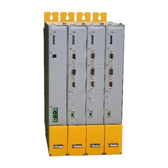
Compax3
Compax3M Installation Manual
Multi-axis devices
Autoryzowany dystrybutor Parker:
53- 012 Wrocław
tel. 71
364 72 82
ul. Wyścigowa 38
fax 71
364 72 83
w w w . a r a p n e u m a t i k . p l
We reserve the right to make technical changes.
The data correspond to the current status at the time of printing.
Electromechanical Automation
Paper version
Release R09-20
09.06.11 08:37
C3Manager-Compax3M
Unterlagen / Software
user guides / tools
manuels / tools:
Compax3 - DVD (english, deutsch, français)
+
Compax3M Installations-Handbuch deutsch
Compax3M Installation Manual english
Manuel technique Compax3M français
192-120148N5 June 2011
Advertisement
Chapters
Table of Contents

Related Manuals for Parker Compax3M


Summary of Contents for Parker Compax3M
- Page 1 / tools Autoryzowany dystrybutor Parker: manuels / tools: Compax3 - DVD (english, deutsch, français) Compax3M Installations-Handbuch deutsch Compax3M Installation Manual english Manuel technique Compax3M français 53- 012 Wrocław tel. 71 364 72 82 ul. Wyścigowa 38...
- Page 2 Tel.: +44 (0)1202 606300 • Fax: +44 (0)1202 606301 E-mail: sales.automation@parker.com mailto:sales.automation@parker.com • Internet: www.parker-eme.com http://www.parker-eme.com Italy: Parker Hannifin S.p.A • SSD SBC • Electromechanical Automation • Via Gounod, 1 I-20092 Cinisello Balsamo (MI), Italy Tel.: +39 (0)2 66012459 • Fax: +39 (0)2 66012808 E-mail: sales.automation@parker.com mailto:sales.sbc@parker.com •...
-
Page 3: Notes On The Documents Supplied
Furthermore, the "Parker Integrated Engineering Tool", a software tool for the Engineering Tool project management of several Parker Motion Control products, can be found on the C3 DVD. Several axes are managed in a common project. The Compax3 ServoManager is integrated per "Plug &... -
Page 4: C3 Servomanager
Notes on the Documents Supplied Multi-axis devices C3 ServoManager Installation of the C3 The Compax3 ServoManager can be installed directly from the Compax3 ServoManager DVD. Click on the corresponding hyperlink resp. start the installation program "C3Mgr_Setup_V..exe" and follow the instructions. PC requirements Recommendation: Operating system:... - Page 5 Parker EME Notes on the Documents Supplied Device Selection In the menu tree under device selection you can read the device type of the connected device (Online Device Identification) or select a device type (Device Selection Wizard). Configuration Then you can double click on "Configuration" to start the configuration wizard. The wizard will lead you through all input windows of the configuration.
-
Page 6: Table Of Contents
Warranty conditions ................15 Conditions of utilization ................ 16 2.7.1. Conditions of utilization for CE-conform operation ........16 2.7.2. Conditions of utilization for UL certification Compax3M ......19 2.7.3. Current on the mains PE (leakage current) ........... 20 2.7.4. Supply networks ....................21 EC declaration of conformity Compax3M .......... - Page 7 Mains supply PSUP (mains module) X41 ............32 3.6.6. Braking resistor / temperature switch PSUP (mains module) ....35 3.6.7. Motor / motor brake Compax3M (axis controller) ........37 3.6.8. Safety technology option for Compax3M (axis controller) ......38 Communication interfaces ..............38 3.7.1.
-
Page 8: Introduction
Cable clamps in different sizes for large area shielding of the motor cable, the screw for the cable clamp as well as the matching plug for the Compax3M connectors X14, X15, X43 a toroidal core ferrite for one cable of the motor holding brake ... -
Page 9: Type Specification Plate
Parker EME Introduction Type specification plate The present device type is defined by the type specification plate (on the housing): Compax3 - Type specification plate (example): Explanation: Type designation The complete order designation of the device (2, 5, 6, 9, 8). - Page 10 Introduction Multi-axis devices Type specification plate: PSUP (example) Explanation: Type designation The complete order designation of the device (2 - 4). PSUPx0:Mains module 3AC 230...480V, nominal power in 1kW (10=10kW) D6: Designation nominal supply Configuration and parameterization interface: USB:USB connection Options: Mxx: I/O extension Unique number of the particular device Date of factory test...
-
Page 11: Packaging, Transport, Storage
Parker EME Introduction Packaging, transport, storage Packaging material and transport Caution! The packaging material is inflammable, if it is disposed of improperly by burning, lethal fumes may develop. The packaging material must be kept and reused in the case of a return shipment. - Page 12 Introduction Multi-axis devices Please note in the event of storage >1 year: Forming the capacitors Forming the capacitors only required with 400VAC axis controllers and PSUP mains module If the device was stored longer than one year, the intermediate capacitors must be re-formed! Forming sequence: Remove all electric connections...
-
Page 13: Safety Instructions
Parker EME Introduction Safety instructions In this chapter you can read about: General hazards ......................13 Safety-conscious working ....................13 Special safety instructions ....................14 2.5.1. General hazards General Hazards on Non-Compliance with the Safety Instructions The device described in this manual is designed in accordance with the latest technology and is safe in operation. -
Page 14: Special Safety Instructions
Introduction Multi-axis devices 2.5.3. Special safety instructions Check the correct association of the device and its documentation. Never detach electrical connections while voltage is applied to them. Safety devices must be provided to prevent human contact with moving or ... -
Page 15: Warranty Conditions
Parker EME Introduction Attention - hot surface! The heat dissipator can reach very high temperatures (>70°C) Protective seals Caution! The user is responsible for protective covers and/or additional safety measures in order to prevent damages to persons and electric accidents. -
Page 16: Conditions Of Utilization
Conditions of utilization In this chapter you can read about: Conditions of utilization for CE-conform operation ............16 Conditions of utilization for UL certification Compax3M ............ 19 Current on the mains PE (leakage current) ..............20 Supply networks ......................21 2.7.1. - Page 17 Never mount the filter housing and the device on paint-coated surfaces! Accessories: Make sure to use only the accessories recommended by Parker Connect all cable shields at both ends, ensuring large contact areas! 192-120148N5 June 2011...
- Page 18 This is a product in the restricted sales distribution class according to EN 61800-3. In a domestic area this product can cause radio frequency disturbance, in which case the user may be required to implement appropriate remedial measures. Autoryzowany dystrybutor Parker: 53- 012 Wrocław tel. 71 364 72 82 ul.
-
Page 19: Conditions Of Utilization For Ul Certification Compax3M
Parker EME Introduction 2.7.2. Conditions of utilization for UL certification Compax3M UL-approval for PSUP/Compax3M conform to UL: according to UL508C Certified E-File_No.: E235342 The UL certification is documented by a “UL” logo on the device (type specification plate). -
Page 20: Current On The Mains Pe (Leakage Current)
Introduction Multi-axis devices 2.7.3. Current on the mains PE (leakage current) Caution! This product can cause a direct current in the protective lead. If a residual current device (RCD) is used for protection in the event of direct or indirect contact, only a type B (all current sensitive) RCD is permitted on the current supply side of this product . -
Page 21: Supply Networks
Parker EME Introduction 2.7.4. Supply networks This product is designed for fixed connection to TN networks (TN-C, TN-C-S or TN- S). Please note that the line-earth voltage may not exceed 300VAC. When grounding the neutral conductor, mains voltages of up to 480VAC are permitted. -
Page 22: Ec Declaration Of Conformity Compax3M
Introduction Multi-axis devices EC declaration of conformity Compax3M 192-120148N5 June 2011... -
Page 23: Ec Declaration Of Conformity Psup
Parker EME Introduction EC declaration of conformity PSUP 192-120148N5 June 2011... -
Page 24: Device Description
Communication interfaces ....................38 Signal interfaces ......................41 Installation instructions Compax3M General introductory notes Operation of the Compax3M multi-axis combination is only possible in connection with a PSUP (mains module). Axis controllers are aligned at the right of the mains module. - Page 25 DIN 912 8.8). Connection of the internal supply voltage. The Compax3M axis controllers are connected to the supply voltages via the rail modules. Details (see on page 31). Deblocking the yellow protective cover with a flat-bladed screwdriver on the ...
-
Page 26: Mounting And Dimensions
Device description Multi-axis devices Mounting and dimensions Ventilation: During operation, the device radiates heat (power loss). Please provide for a sufficient mounting distance below and above the device in order to ensure free circulation of the cooling air. Please do also respect the recommended distances of other devices. -
Page 27: Mounting And Dimensions Psup20/Psup30/C3M300D6
Parker EME Device description 3.2.2. Mounting and dimensions PSUP20/PSUP30/C3M300D6 Information on PSUP20/PSUP30/C3M300D6 Mounting: 4 socket head screws M5 101mm 50,5mm 50,5mm 263mm 90° 400mm 360mm 96mm 100mm Tolerances: DIN ISO 2768-f 3.2.3. With upper mounting, the housing design may be different... -
Page 28: State Of Delivery
Device description Multi-axis devices State of delivery Compax3 is delivered without configuration! After switching on the 24VDC supply, the red LED is flashing while the green LED is dark. Please configure the device with the help of the Windows-Software "Compax3 ServoManager"! Meaning of the status LEDs - Compax3 axis controller Device status LEDs... -
Page 29: Psup/Compax3M Connections
Control voltage 24VDC PSUP (mains module) ..............32 Mains supply PSUP (mains module) X41................. 32 Braking resistor / temperature switch PSUP (mains module) ........... 35 Motor / motor brake Compax3M (axis controller) ............. 37 Safety technology option for Compax3M (axis controller)..........38 3.6.1. -
Page 30: Connections On The Device Bottom
Device description Multi-axis devices 3.6.2. Connections on the device bottom Caution - Risk of Electric Shock! Always switch devices off before wiring them! Dangerous voltages are still present until 10 min. after switching off the power supply. Caution! When the control voltage is missing there is no indication whether or not high voltage supply is available. -
Page 31: Connections Of The Axis Combination
Parker EME Device description 3.6.3. Connections of the axis combination The axis controllers are connected to the supply voltages via rails. Supply voltage 24VDC DC power voltage supply The rails can be found behind the yellow protective covers. In order to connect the rails of the devices, you may have to remove the yellow plastic device inserted at the side. -
Page 32: Control Voltage 24Vdc Psup (Mains Module)
Current drain PSUP PSUP20 / PSUP30: 0.3A C3M050D6: 0.85 3M100D6: 0.85A C3M150D6: 0.85A Electric current drain Compax3M C3M300D6: 1.0 A + Total load of the digital outputs + current for the motor holding brake 3.6.5. Mains supply PSUP (mains module) X41... - Page 33 Parker EME Device description Connector X41 Designation Earth conductor Phase 3 Phase 2 Phase 1 Mains connection PSUP10D6 Device type PSUP10 230V 400V 480V 230VAC ±10% 400VAC ±10% 480VAC ±10% Supply voltage 50-60Hz 50-60Hz 50-60Hz Rated voltage 3AC 230V 3AC 400V...
- Page 34 Device description Multi-axis devices PSUP30D6 Mains connection Device type PSUP30 230V 400V 480V Supply voltage 230VAC ±10% 400VAC ±10% 480VAC ±10% 50-60Hz 50-60Hz 50-60Hz Rated voltage 3AC 230V 3AC 400V 3AC 480V Input current 50Arms 50Arms 42Arms Output voltage 325VDC ±10% 565VDC ±10% 680VDC ±10% Output power...
-
Page 35: Braking Resistor / Temperature Switch Psup (Mains Module)
Parker EME Device description Dimensional drawing: LCG-0055-0.45 mH-UL Caution - Risk of Electric Shock! Always switch devices off before wiring them! Dangerous voltages are still present until 10 min. after switching off the power supply. 3.6.6. Braking resistor / temperature switch PSUP (mains module) The energy generated during braking operation must be dissipated via a braking resistor. - Page 36 Device description Multi-axis devices Braking operation PSUPxxD6 (mains module) Device type PSUP10 PSUP20 PSUP30 Capacitance / storable 550 µF/ 1175 µF/ 1175 µF/ energy 92 Ws at 400 V 197 Ws at 400 V 197 Ws at 400 V 53 Ws at 480 V 114 Ws at 480 V 114 Ws at 480 V Minimum braking-...
-
Page 37: Motor / Motor Brake Compax3M (Axis Controller)
Parker EME Device description 3.6.7. Motor / motor brake Compax3M (axis controller) Connector X43 Designation Motor cable lead designation* Motor holding brake * Motor holding brake * PE (motor) YE / GN YE / GN YE / GN W (motor) -
Page 38: Communication Interfaces
STO-GND STO2/ +24VDC STO-GND Note! If the Compax3M axis controller features a safety option, these connections must also be wired, otherwise it is not possible to set up the axis. Communication interfaces 3.7.1. Communication Compax3M In this chapter you can read about: PC - PSUP (Mains module) ..................... - Page 39 X31 of the next device. On the first device (X31) and the last device (X30) in the multi-axis combination, a bus termination plug (BUS07/01) is required. Orientation to the back side PSUP (Mains module) res. factory use Compax3M (axis) res. factory use Orientation to the front plate 3.7.1.3 Adjusting the basic address On the mains module, the basic address of the device combination is set in steps of 16 with the aid of the first three dip switches.
- Page 40 The value of switch S10 on the axis controller is stored in object O110.1 C3plus.Switch_DeviceFunction and can be evaluated with the aid of a program. This helps realize a more simple function selection. Autoryzowany dystrybutor Parker: 53- 012 Wrocław tel. 71 364 72 82 ul.
-
Page 41: Signal Interfaces
Parker EME Device description Signal interfaces In this chapter you can read about: Resolver / feedback (plug X13) ..................41 Analogue / encoder (plug X11) ..................42 Digital inputs/outputs (plug X12) ..................43 3.8.1. Resolver / feedback (plug X13) Feedback /X13 High Density /Sub D... -
Page 42: Analogue / Encoder (Plug X11)
Device description Multi-axis devices 3.8.2. Analogue / encoder (plug X11) PIN X11 Reference High Density Sub D Encoders +24V (output) max. 70mA Ain1 -; analog input - (14Bits; max. +/-10V) D/A monitor channel 1 (±10V, 8-bit resolution) D/A monitor channel 0 (±10V, 8-bit resolution) +5 V (output for encoder) max. -
Page 43: Digital Inputs/Outputs (Plug X12)
Parker EME Device description 3.8.3. Digital inputs/outputs (plug X12) Pin X12 Input/output I/O / X12 High density/Sub D Output +24 V DC output (max. 340mA) Output 0 (max. 100 mA) Output 1 (max. 100mA) Output 2 (max. 100mA) Output 3 (max. 100mA) -
Page 44: Technical Characteristics
Technical Characteristics Multi-axis devices 4. Technical Characteristics Size / weight PSUP/Compax3M Dimensions HxWxD Weight Device type [mm] [kg] PSUP10D6 360 x 50 x 263 3.95 PSUP20D6 & PSUP30D6 360 x 100 x 263 Compax3M050D6 360 x 50 x 263 Compax3M100D6... - Page 45 Current drain PSUP PSUP20 / PSUP30: 0.3A C3M050D6: 0.85 3M100D6: 0.85A C3M150D6: 0.85A Electric current drain Compax3M C3M300D6: 1.0 A + Total load of the digital outputs + current for the motor holding brake Output data Compax3Mxxx at 3*230VAC Device type Compax3...
- Page 46 Technical Characteristics Multi-axis devices Output data Compax3Mxxx at 3*400VAC Device type Compax3 M050D6 M100D6 M150D6 M300D6 Input voltage 565VDC ±10% Output voltage 3x 0-400V (0...500Hz) Nominal output current 5Arms 10Arms 15Arms 30Arms Pulse current for 5s* 10Arms 20Arms 30Arms 60Arms Power 3.33kVA 6.66kVA...
- Page 47 Distance coding with 1VSS - Interface Distance coded feedback systems Distance coding with RS422 - Interface (Encoder) *Max. differential input between SIN- (X13/7) and SIN+ (X13/8). ** Limit frequency = 1MHz for Compax3M (higher bandwidths on request) 192-120148N5 June 2011...
- Page 48 Motor holding brake output Motor holding brake output Compax3 Voltage range 21 – 27VDC Maximum output current (short circuit 1.6A proof) Securing of brake Compax3M 3.15A UL-approval for PSUP/Compax3M conform to UL: according to UL508C Certified E-File_No.: E235342 ...
- Page 49 Parker EME Technical Characteristics Compax3M S1 Option: Signal inputs for connector X14 Nominal voltage of the inputs Required isolation of the Grounded protective extra low voltage, PELV 24V control voltage Protection of the STO control voltage Number of inputs Signal inputs via Low = 0...7V DC or open...
- Page 50 Technical Characteristics Multi-axis devices EMV limit values PSUP/Compax3M EMC interference emission Limit values in accordance with EN 61 800-3, Limit value class C3 with mains filter. EMC disturbance immunity Industrial area limit values in accordance with EN 61 800-3 EC directives and applied harmonized EC norms...
-
Page 51: Index
Digital inputs/outputs (plug X12) - 43 Scope of delivery - 8 Setting the axis function - 40 Signal interfaces - 41 EC declaration of conformity Compax3M - 22 Special safety instructions - 14 EC declaration of conformity PSUP - 23 State of delivery - 28... - Page 52 Wiring of analog interfaces - 42 With upper mounting, the housing design may be different - 27 X11 - 42 X12 - 43 X13 - 41 Autoryzowany dystrybutor Parker: 53- 012 Wrocław tel. 71 364 72 82 ul. Wyścigowa 38 fax 71 364 72 83 w w w .
Need help?
Do you have a question about the Compax3M and is the answer not in the manual?
Questions and answers