Parker Compax3 Fluid T40 Operating Instructions Manual
Hydraulics controller
Hide thumbs
Also See for Compax3 Fluid T40:
- Operating instructions manual (398 pages) ,
- Start-up (40 pages) ,
- Installation manual (28 pages)
Table of Contents
Advertisement
Quick Links
See also:
Installation Manual
Compax3
Operating instructions Compax3 Fluid T40: Cam
Hydraulics controller
Autoryzowany dystrybutor Parker:
53- 012 Wrocław
tel. 71
364 72 82
ul. Wyścigowa 38
fax 71
364 72 83
w w w . a r a p n e u m a t i k . p l
Technische Änderungen vorbehalten.
Daten entsprechen dem technischen Stand zum Zeitpunkt der Drucklegung.
Electromechanical Automation
Release R08-0
18.06.08 14:42
192-121102 N04
192-121102 N04 June 2008
June 2008
Advertisement
Chapters
Table of Contents

Subscribe to Our Youtube Channel
Related Manuals for Parker Compax3 Fluid T40


Summary of Contents for Parker Compax3 Fluid T40
- Page 1 Compax3 Electromechanical Automation Operating instructions Compax3 Fluid T40: Cam Hydraulics controller Autoryzowany dystrybutor Parker: 192-121102 N04 June 2008 53- 012 Wrocław tel. 71 364 72 82 Release R08-0 ul. Wyścigowa 38 fax 71 364 72 83 w w w . a r a p n e u m a t i k . p l Technische Änderungen vorbehalten.
- Page 2 Reg. Nr. 36 38 E-mail: sales.automation@parker.com mailto:sales.automation@parker.com Parker Hannifin GmbH & Co. KG - registered office: Bielefeld - Amtsgericht: Bielefeld HRA 14808 Personally liable shareholder: Parker Hannifin Management GmbH - Amtsgericht: Bielefeld HRB 35489 executive board: Dr. Gerd Scheffel, Günter Schrank, Christian Stein, Kees Veraart, Hans Wolfs - Chairman of the board: Hansgeorg...
-
Page 3: Table Of Contents
Parker EME Introduction Contents 1. Introduction.....................12 Device assignment Compax3 Fluid............12 1.1.1. Type specification plate Compax3 Fluid ............13 Safety Instructions................. 14 1.2.1. General hazards....................14 1.2.2. Safety-conscious working .................. 14 1.2.3. Special safety instructions ................. 15 Warranty conditions ................15 Conditions of utilization for CE-conform operation...... - Page 4 Introduction C3F_T40 3.2.15. Mounting and dimensions .................. 40 4. Setting up Compax3................41 Configuration ..................41 4.1.1. C3HydraulicsManager ..................44 4.1.1.1 Function description.................. 44 4.1.1.2 Structure of the databases................ 44 4.1.2. Compax3F structure image ................45 4.1.3. Drive configuration....................46 4.1.4. Configuring drive1....................
- Page 5 Parker EME Introduction 4.3.2.3 Example: Setting the Oscilloscope ............95 4.3.3. Control Loop Dynamics ..................97 4.3.3.1 Preparatory settings for the controller alignment........98 4.3.3.2 Signal filtering with external command value ........... 102 4.3.3.3 Controller structure of main axis ............... 105 4.3.3.4...
- Page 6 Introduction C3F_T40 Control functions ................. 165 5.3.1. Activation of the drive (MC_Power) ..............165 5.3.2. Stop (MC_Stop)....................166 5.3.2.1 MC_Stop at pressure/force control ............167 5.3.2.2 MC_Stop: Example 1 ................167 5.3.2.3 MC_Stop: Example 2 ................168 5.3.3. C3_SetControlMode .................... 169 Reading values..................
- Page 7 Parker EME Introduction 5.10.6. Master signal source ................... 235 5.10.6.1 Setting the position of the selected master source (C3_SetMaster)..................236 5.10.6.2 Recording the position of the selected master source (C3_MasterControl) .................. 237 5.10.6.3 Control of the cam generator (C3_CamTableSelect) ....... 240 5.10.6.4 C3_MasterConfig ..................
- Page 8 5.13.4. Memorizing the signals with the trigger event (C3_TouchProbe) ....306 5.13.5. Integration of Parker I/Os (PIOs) ................ 309 5.13.5.1 Initializing the PIOs (PIO_Init)..............309 5.13.5.2 Reading the PIO inputs 0-15 (PIO_Inputx...y) .......... 310 5.13.5.3 Writing the PIO outputs 0-15 (PIO_Outputx...y) ........311 5.13.5.4 Example: Compax3 as CANopen Master with PIOs ........
- Page 9 Parker EME Introduction Profibus ....................354 6.4.1. Typical application with fieldbus and IEC61131..........354 6.4.2. Profibus configuration ..................354 6.4.2.1 Configuration of the process-data channel ..........355 6.4.2.2 PKW parameter channel................356 6.4.2.3 Error reaction to a bus failure ..............356 6.4.3.
- Page 10 Introduction C3F_T40 6.8.2. HEDA expansion (HEDA advanced) ..............393 6.8.2.1 The possibilities of the HEDA expansion..........393 6.8.2.2 Technical data of the HEDA interface / overview ........394 6.8.2.3 Definitions ....................395 6.8.2.4 Calling up the HEDA wizard in the C3 ServoManager ......395 6.8.2.5 Configuration of the HEDA communication ..........
- Page 11 Parker EME Introduction 11.6.1.1 Assignment of the X22 connector............. 447 11.6.2. HEDA (motion bus) - Option M11............... 448 11.6.3. Option M10 = HEDA (M11) & I/Os (M12) ............450 11.7 Profibus plug BUS08/01 ..............451 11.8 CAN - plug BUS10/01................452 11.9 PIO: Inputs/Outputs ................
-
Page 12: Introduction
Introduction C3F_T40 1. Introduction In this chapter you can read about: Device assignment Compax3 Fluid..................12 Safety Instructions ......................14 Warranty conditions......................15 Conditions of utilization for CE-conform operation .............15 Device assignment Compax3 Fluid This manual applies to the following devices: C3 F001 D2 F12 I11 T40 C3 F001 D2 F12 I20 T40 C3 F001 D2 F12 I21 T40 C3 F001 D2 F12 I22 T40... -
Page 13: Type Specification Plate Compax3 Fluid
Parker EME Introduction 1.1.1. Type specification plate Compax3 Fluid You will find the exact description of the device on the type specification plate, which is located on the right side of the device: Type specification plate Compax3 Fluid: Explanation: Type designation The complete order designation of the device (2, 6, -9...) -
Page 14: Safety Instructions
Introduction C3F_T40 Safety Instructions In this chapter you can read about: General hazards .........................14 Safety-conscious working....................14 Special safety instructions ....................15 1.2.1. General hazards General Hazards on Non-Compliance with the Safety Instructions The device described in this manual is designed in accordance with the latest technology and is safe in operation. -
Page 15: Special Safety Instructions
Parker EME Introduction 1.2.3. Special safety instructions Check the correct association of the device and its documentation. Never detach electrical connections while voltage is applied to them. Safety devices must be provided to prevent human contact with moving or rotating parts. - Page 16 Signal leads should never pass close to excessive sources of interference (motors, transformers, contactors etc.). Accessories: Make sure to use only the accessories recommended by Parker Connect all cable shields at both ends, ensuring large contact areas! Warning: This is a product in the restricted sales distribution class according to EN 61000-6-4.
-
Page 17: Positioning With Iec61131-3
Parker EME Positioning with IEC61131-3 2. Positioning with IEC61131-3 Compax3F: Compax3F is another member of the Parker Hannifin servo drive family. Electrohydraulic Compax3F was especially designed to meet the requirements of electrohydraulic servo drive systems for the control of position and force of hydraulic axes. - Page 18 The Motion Control functions specified in PLCopen are also provided by Parker as a library with the device and control software. The graphical program editor supports the following functions:...
- Page 19 Parker EME Positioning with IEC61131-3 In particular mechanical cam switching mechanisms and discontinuous shafts maintained until today their fields of application in many areas of machine construction. Mechanical cam switching mechanisms offer, besides complex motion profiles, a high positioning accuracy and rigid coupling between master and slave drive.
- Page 20 Positioning with IEC61131-3 C3F_T40 Model / standards / The structure and size of the device are of considerable importance. Powerful auxiliary material electronics is an important feature which made it possible to manufacture the Compax3F so small and compact. All connectors are located on the front of the Compax3.
-
Page 21: Compax3F Device Description
Parker EME Compax3F device description 3. Compax3F device description In this chapter you can read about: State of delivery........................21 Plug and connector assignment Compax3 Fluid..............21 State of delivery Compax3 is delivered without configuration! After switching on the 25VDC supply, the red LED is flashing while the green LED is dark. -
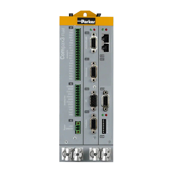
Page 22: Plug And Connector Assignment
Compax3F device description C3F_T40 3.2.2. Plug and connector assignment LED1 Analog Inputs Analog Outputs 24 VDC power supply RS232/RS485 2. Feedback Type Inputs/Outputs 1. Feedback Type Always switch devices off before wiring them! 192-121102 N04 June 2008... -
Page 23: Plug And Connector Assignment Complete
Parker EME Compax3F device description 3.2.3. Plug and connector assignment complete In detail: The fitting of the different plugs depends on the extension level of Compax3. In part, the assignment depends on the Compax3 option implemented. 192-121102 N04 June 2008... - Page 24 Compax3F device description C3F_T40 Compax3F X20/1 X10/1 X10/1 X10/1 RS485 +5V RS485 +5V EnableRS232 0V X20/2 X10/2 X10/2 X10/2 res. X20/3 X10/3 X10/3 X10/3 Analog Input TxD/ TxD_RxD/ X10/4 X20/4 X10/4 X10/4 res. res. res. X20/5 X10/5 X10/5 X10/5 X1/1 res.
-
Page 25: Analog Input (Plug X1)
Parker EME Compax3F device description 3.2.4. Analog Input (plug X1) Connector X1 Description Combicon 3,81mm; female connector Supply Sensor 0 Supply Sensor 0 IN0+ Signal Sensor 0 + IN0- Signal Sensor 0 - Supply Sensor 1 Supply Sensor 1 IN1 +... -
Page 26: Analog Output (Plug X2)
Compax3F device description C3F_T40 3.2.5. Analog Output (plug X2) Plug X2 Descripti Combicon 3,81mm; female connector I/U Aout0 ±10V/10mA or 4..20mA GND 0 I/U Aout1 ±10V/10mA or 4..20mA GND 1 I/U Aout2 ±10V/10mA or 4..20mA GND 2 I/U Aout3 ±10V/10mA or 4..20mA GND 3 Iout 0 +/-100mA current output 0... -
Page 27: Voltage Supply (Plug X3)
Parker EME Compax3F device description 3.2.6. Voltage supply (plug X3) Connector Descriptio Combicon 5mm X3 Pin +24 V 24 VDC (power supply) Gnd 24 V Voltage supply 24VDC Controller type Compax3 F001 D2 Voltage range 21 - 27VDC Mains module... -
Page 28: Analog / Encoder (Plug X11)
Compax3F device description C3F_T40 RS485 4-wire RS485 four wire (Sub D) Pin 1 and 9 externally jumpered Enable RS485 (+5V) TxD/ res. res. RxD/ USB - RS232/RS485 converter The following USB - RS232 converters were tested: ATEN UC 232A USB GMUS-03 (available under several company names) USB / RS485: Moxa Uport 1130 http://www.moxa.com/product/UPort_1130.htm Ethernet/RS232/RS485: NetCom 113 http://www.vscom.de/666.htm 3.2.8. -
Page 29: Connections Of The Encoder Interface
Parker EME Compax3F device description 3.2.8.1 Connections of the encoder interface Compax3 1K Ω 121 Ω RS422 Transceiver 10nF A B N 1K Ω The input connection is available in triple (for A & /A, B & /B, N & /N) 3.2.9. -
Page 30: Connection Of The Digital Outputs/Inputs
Compax3F device description C3F_T40 3.2.9.1 Connection of the digital Outputs/Inputs Wiring of digital outputs Status of digital inputs Compax3 Compax3 SPS/PLC SPS/ X12/1 X12/1 X12/11 100K Ω 22K Ω X12/6 X12/2 22K Ω 10nF 10K Ω Ω 18.2K Ω X12/15 X12/15 The circuit example is valid for all digital outputs! The circuit example is valid for all digital inputs! -
Page 31: Connections Of The Encoder Interface
Parker EME Compax3F device description 1. Feedback system / X13 High Density /Sub D RS422 Encoder SinusCosinus EnDat 2.1 Start / Stop 1VSS (Time of Flight) +24V +24V max. 100mA max. 100mA Sense + Sense + Sense + Sin +... -
Page 32: Profibus Connector X23 With Interface I20
Compax3F device description C3F_T40 3.2.11. Profibus connector X23 with Interface I20 Pin X23 Profibus (Sub D) Reserved Reserved Data line B Reserved Data line A Reserved The assignment corresponds to Profibus standard EN 50170. Wiring (see page 451). 3.2.11.1 Adjusting the bus address Address setting Values: 1: 2... -
Page 33: Canopen Connector X23 Interface I21
Parker EME Compax3F device description 3.2.12. CANopen connector X23 Interface I21 Pin X23 CANopen (Sub D) Reserved CAN_L CAN Low GNDfb Opto-isolated GND-supply Reserved SHIELD Shield optional Reserved CAN_H CAN High Reserved Reserved The assignment corresponds to CANopen DS301. At the beginning and end of the device chain a terminating resistor of 120Ω is required between CAN_L and CAN_H Wiring (see page 452). -
Page 34: Function Of The Bus Leds
Compax3F device description C3F_T40 3.2.12.2 Function of the Bus LEDs LED red No. Signal Status Description No Error The bus is operating Single flash Warning at least one of the error counters of the CAN controller has reached the warning level. Double flash Error Node Guarding Error... -
Page 35: Devicenet Connector X23
Parker EME Compax3F device description 3.2.13. DeviceNet connector X23 Pin X23 DeviceNet (Open Plug Phoenix MSTB 2.5/5-GF5.08 ABGY AU) Mass CAN- CAN Low Shield Shield CAN+ CAN High not required, internal supply A mating plug is included in the delivery. -
Page 36: Function Of The Bus Leds
Compax3F device description C3F_T40 3.2.13.2 Function of the Bus LEDs LED (red) No. Signal Status Description No Error The bus is operating Single flash Warning at least one of the error counters of the CAN controller has reached the warning level. Double flash Error Communication Fault... -
Page 37: Set Ethernet Powerlink (Option I30) Bus Address
Parker EME Compax3F device description 3.2.14.1 Set Ethernet Powerlink (option I30) bus address Automatic address assignment with EtherCAT Address setting Values: 1: 2 ; 2: 2 ; 3: 2 ; ... 7: 2 ; 8: 2 Settings: left: OFF right: ON (The address is set to 0 in the illustration) Range of values: 1 ... -
Page 38: Meaning Of The Bus Leds (Ethercat)
Compax3F device description C3F_T40 3.2.14.3 Meaning of the Bus LEDs (EtherCAT) Red LED (right): EtherCAT error LED is influenced by the transitions of the status diagram Error LED Error: Description No Error Flickering Boot error Error during initialization Blinking Invalid configuration Single Flash Unsolicited change of Slave changed the status independently... - Page 39 Parker EME Compax3F device description Meaning of the LED states 50 ms flickering blinking (ERR) blinking (RUN) single flash 1000 (ERR) single flash 1000 (RUN) double flash 1000 (ERR) 192-121102 N04 June 2008...
-
Page 40: Mounting And Dimensions
Compax3F device description C3F_T40 3.2.15. Mounting and dimensions Mounting: 3 socket head screws M5 or by direct snapping on a 35mm supporting rail (according to DIN EN 50 022), Mounting material: DIN rail clip and distance piece available as accessories - Set ZBH02/04 (see page 432) 17,5 Stated in mm... -
Page 41: Setting Up Compax3
Parker EME Setting up Compax3 4. Setting up Compax3 In this chapter you can read about: Configuration ........................41 Configuring the signal source.....................82 Optimization ........................87 Configuration In this chapter you can read about: C3HydraulicsManager ......................44 Compax3F structure image ....................45 Drive configuration......................46 Configuring drive1 ......................47... - Page 42 Setting up Compax3 C3F_T40 Configuration sequence: Installation of the C3 The Compax3 ServoManager can be installed directly from the Compax3 ServoManager DVD. Click on the appropriate hyperlink or start the installation program "C3Mgr_Setup_V..exe" and follow the instructions. PC requirements Recommendation: Operating system: MS Windows XP SP2 / MS Windows 2000 as from SP4 / (MS Vista)
- Page 43 Parker EME Setting up Compax3 Connection between Your PC is connected with Compax3 via a RS232 cable (SSK1 (see page 441)). Cable SSK1 (see page 441) (COM 1/2-interface on the PC to X10 on the Compax3 PC - Compax3 or via adapter SSK32/20 on programming interface of Compax3H).
-
Page 44: C3Hydraulicsmanager
Compax3 configuration with the aid of these characteristic values. An up-to-date Parker component database can be downloaded from the internet. The customer component databases are not overwritten. -
Page 45: Compax3F Structure Image
Parker EME Setting up Compax3 4.1.2. Compax3F structure image 10V/10mA Conditioning Chain 0 X2/1 MC_MoveAbsolute 0 ... 20mA Main axis MC_MoveAdditive P B P 0 ± 100mA X2/9 MC_MoveRelative Pos Control 1 MC_MoveSuperImposed MC_MoveVelocity MC_CamIn Main axis 10V/10mA Conditioning Chain 1... -
Page 46: Drive Configuration
Setting up Compax3 C3F_T40 Components of Compax3F: 4 controllers for 2 axes Main axis position controller (Main axis: Pos Control 1) Main axis pressure difference / force controller (Main axis: PressureForce Control 1) Auxiliary axis position controller (Auxiliary axis: Pos Control 2) Auxiliary axis pressure difference / force controller (Auxiliary axis: PressureForce Control 2) 4 Conditioning Chains for the liearisation of the valves and cylinders... -
Page 47: Configuring Drive1
Parker EME Setting up Compax3 4.1.4. Configuring drive1 In this chapter you can read about: Position feedback system drive1 ..................47 Cylinder / motor selection ....................48 Load configuration drive1 ....................48 4.1.4.1 Position feedback system drive1 If the position feedback system is part of the cylinder / motor, it has already been parameterized in the C3HydraulicsManager and this step is not needed. -
Page 48: Cylinder / Motor Selection
4.1.4.2 Cylinder / motor selection The selection is made from the hdydraulics database. Parker cylinders or Parker motors are stored there. Furthermore you can create customer-specific cylinders/motors with the aid of the C3HydraulicsManager and then select them here. The selection of the drive is separated as follows: Parker Cylinder Customer cylinders. -
Page 49: Configuring Drive2
Parker EME Setting up Compax3 4.1.5. Configuring drive2 The following dialogs can only be selected, if under "number of drives" 2 drives were selected. Drive2 is configured as described under drive1, the selection of the path measurement system EnDat and Sine/Cosine is however not available for drive2. -
Page 50: Force Sensor Drive 1
Setting up Compax3 C3F_T40 Interface: Select the interface where the sensor is connected. Only the freely available inputs are displayed. I, U (1) pressure min.: Enter the minimum pressure. (2) pressure max.: Enter the maximum pressure. (3) Sensor signal min.: Enter the minimum singal of the pressure sensor. (4) Sensor signal max.: Enter the maximum singal of the pressure sensor. -
Page 51: Pressure And Force Sensor Drive 2
Parker EME Setting up Compax3 If a force sensor is used for force control, the following parameters must be entered: Interface: Select the interface where the sensor is connected. Only the freely available inputs are displayed. I, U Force min.: Enter the minimum force (1). -
Page 52: Selection And Configuration Of The Valves
Selection and configuration of the valves The selection of the respective valves is made from the hdydraulics database. You can choose between Parker valves or customized valves that were created with the aid of the C3HydraulicsManager from the database. The valves in the valve database are structured as follows:... -
Page 53: Defining The Reference System
Parker EME Setting up Compax3 Control range of the position controller. The "control range" parameter -100%...100% 0...100% (P -> A) -100%...0 (A -> T) 0...100% (B -> T) -100%...0 (P -> B) defines the output range of the position controller for the selected valve. -
Page 54: Machine Zero
Setting up Compax3 C3F_T40 4.1.8.2 Machine Zero In this chapter you can read about: Positioning after homing run ....................54 Machine zero speed and acceleration ................55 Machine zero modes overview ..................56 Homing modes with home switch (on X12/14) ..............58 Machine zero modes without home switch ................ -
Page 55: Machine Zero Speed And Acceleration
Parker EME Setting up Compax3 Without positioning after homing run The position reached is not exactly on 0, as the drive brakes when detecting the home and stops: Please note: In controlled operation (open loop) no machine zero run is possible! -
Page 56: Machine Zero Modes Overview
Setting up Compax3 C3F_T40 Machine zero modes overview Selection of the machine zero modes (MN-M) Machine home switch Without motor reference point without direction reversal switches: MN-M 19, 20 (see page 58), on X12/14: MN-M 21, 22 (see page 59) MN-M 19 ...30 MN-M 3 ... - Page 57 Parker EME Setting up Compax3 Example axis with the initiator signals Direction reversal / end switch on the negative end of the travel range (the assignment of the reversal / end switch inputs (see page 74) to travel range side can be changed).
-
Page 58: Homing Modes With Home Switch (On X12/14)
Setting up Compax3 C3F_T40 Homing modes with home switch (on X12/14) In this chapter you can read about: Without motor reference point ................... 58 With motor reference point ....................62 Without motor reference point In this chapter you can read about: Without direction reversal switches ................... - Page 59 Parker EME Setting up Compax3 MN-M 21.22: MN initiator = 1 on the negative side The MN initiator can be positioned at any location within the travel range. The travel range is then divided into 2 contiguous ranges: one range with deactivated MN initiator (positive part of the travel range) and one range with activated MN initiator (negative part of the travel range).
- Page 60 Setting up Compax3 C3F_T40 With direction reversal switches In this chapter you can read about: MN-M 1, 2: Limit switch as machine zero ................68 MN-M 132, 133: Determine absolute position via distance coding with direction reversal switches ............................69 In this chapter you can read about: MN-M 7...10: Direction reversal switches on the positive side ..........
- Page 61 Parker EME Setting up Compax3 MN-M 27...30: With direction reversal switches on the negative side Without motor zero point, with direction reversal switches 1: Logic state of the home switch 2: Logic state of the direction reversal switch 192-121102 N04 June 2008...
- Page 62 Setting up Compax3 C3F_T40 With motor reference point In this chapter you can read about: Without direction reversal switches ................... 62 With direction reversal switches ..................63 Without direction reversal switches MN-M 3.4: MN-Initiator = 1 on the positive side The MN initiator can be positioned at any location within the travel range.
- Page 63 Parker EME Setting up Compax3 MN-M 5.6: MN initiator = 1 on the negative side The MN initiator can be positioned at any location within the travel range. The travel range is then divided into 2 contiguous ranges: one range with deactivated MN initiator (positive part of the travel range) and one range with activated MN initiator (negative part of the travel range).
- Page 64 Setting up Compax3 C3F_T40 MN-M 7...10: Direction reversal switches on the positive side With motor zero Machine zero modes with a home switch which is activated in the middle of the point, with direction travel range and can be deactivated to both sides. reversal switches 1: Motor zero point 2: Logic state of the home switch...
-
Page 65: Machine Zero Modes Without Home Switch
Parker EME Setting up Compax3 Machine zero modes without home switch In this chapter you can read about: Without motor reference point ................... 65 With motor reference point ....................67 Without motor reference point In this chapter you can read about: MN-M 35: MN at the current position................. - Page 66 Setting up Compax3 C3F_T40 MN-M 17.18: Limit switch as machine zero 1: Logic state of the direction reversal switch Function Reversal via Following error threshold If no direction reversal switches are available, the reversal of direction can also be performed during the machine zero run via the function ”direction reversal via Following error threshold"...
- Page 67 Parker EME Setting up Compax3 With motor reference point In this chapter you can read about: Machine zero only from motor reference ................67 With direction reversal switches ..................68 Machine zero only from motor reference In this chapter you can read about: MN-M 33,34: MN at motor zero point ................
- Page 68 Setting up Compax3 C3F_T40 With direction reversal switches Machine zero modes with a home switch which is activated in the middle of the travel range and can be deactivated to both sides. The assignment of the direction reversal switches (see page 74) can be changed.
-
Page 69: Adjusting The Machine Zero Proximity Switch
Parker EME Setting up Compax3 MN-M 132, 133: Determine absolute position via distance coding with direction reversal switches Only for motor feedback with distance coding (the absolute position can be determined via the distance value). Compax3 determines the absolute position from the distance of two signals and then stops the movement (does not automatically move to position 0). -
Page 70: Travel Limit Settings
Setting up Compax3 C3F_T40 4.1.8.3 Travel Limit Settings Please note: Both the software and the hardware end limits are the same for the main axis and the auxiliary axis! Software end limits The error reaction when reaching the software end limits can be set: Possible settings for the error reaction are: No response downramp / stop... - Page 71 Parker EME Setting up Compax3 Software end limit in continuous mode Each individual positioning is confined within the travel limits. A positioning order aiming at a target outside the software end limits is not executed. The reference is the respective current position.
- Page 72 Setting up Compax3 C3F_T40 Behavior with software end limits of a referenced axis Position within Position outside Position outside target outside target outside and aiming target within and aiming in the opposite direction in the direction of the of the travel range travel range JOG +/- Positioning up to the end...
- Page 73 Parker EME Setting up Compax3 Hardware end limits The error reaction when reaching the hardware end limits can be set: Possible settings for the error reaction are: No response downramp / stop Downramp / switch to currentless (standard setting) Hardware end limits are realized with the aid of end switches.
-
Page 74: Change Assignment Direction Reversal / Limit Switches
Setting up Compax3 C3F_T40 4.1.8.4 Change assignment direction reversal / limit switches If this function is not activated, the direction reversal / end switches are assigned as follows: Direction reversal / limit switch on E5 (X12/12): negative side of the travel range Direction reversal / limit switch on E6 (X12/13): Direction reversal / limit switch on E6 (X12/13): Change assignment... -
Page 75: Limit And Monitoring Settings Of Force
Parker EME Setting up Compax3 4.1.10. Limit and monitoring settings of force In this chapter you can read about: Force window - force achieved...................75 Maximum control deviation of force controller ..............76 Maximum force ........................76 Hydraulic corner power limitation ..................76 Please note:... -
Page 76: Maximum Control Deviation Of Force Controller
Setting up Compax3 C3F_T40 4.1.10.2 Maximum control deviation of force controller The force control deviation is a dynamic error. The dynamic difference between the setpoint force and the actual force during a force control is called the force control deviation. Do not confuse this with the static difference which is always 0;... -
Page 77: Positioning Window - Position Reached
Parker EME Setting up Compax3 The corner power limitation can only be activated, if at least one pressure sensor for pA or pB and p0 was parameterized before. Note: Currently, the corner power is calculated; which must however, if necessary, be limited in the IEC program! the corner power can be read from the objects C3.HydraulicPower_Axis1,... -
Page 78: Following Error Limit
Setting up Compax3 C3F_T40 4.1.12. Following error limit The error reaction upon a following error can be set: Possible settings for the error reaction are: No response downramp / stop Downramp / switch to currentless (standard setting) The following error is a dynamic error. The dynamic difference between the setpoint position and the actual position during a positioning is called the following error. -
Page 79: Encoder Simulation
Parker EME Setting up Compax3 4.1.14. Encoder Simulation You can make use of a permanently integrated encoder simulation feature to make the actual position value available to additional servo drives or other automation components. Caution! The encoder simulation is not possible at the same time as the encoder input resp. -
Page 80: Recipe Table
Setting up Compax3 C3F_T40 4.1.15. Recipe table If you would like to work with the recipe array (see page 157), (e.g. for the storage of variable machine data) you can make preassignments in it with Compax3 ServoManager. Note: The recipe array can also be loaded separately into the device (>button on the right side). -
Page 81: Configuration Name / Comments
Parker EME Setting up Compax3 4.1.17. Configuration name / comments Here you can name the current configuration as well as write a comment. Then you can download the configuration settings or, in T30 or T40 devices, perform a complete Download (with IEC program and curve). -
Page 82: Configuring The Signal Source
Setting up Compax3 C3F_T40 Configuring the signal source In this chapter you can read about: Physical Source........................82 Internal virtual master ......................85 HEDA Master signal source ....................85 Possible master signal sources Under the tree entry ”Configuring the signal source” of the C3 ServoManager you can configure 3 signal sources for Master –... - Page 83 Parker EME Setting up Compax3 The dimensional reference to the master is established via the following settings: Travel path per motor revolution master axis numerator = 50mm or with a rotary feedback system: Travel per feedback revolution. With denominator = 1 the value can be entered directly.
- Page 84 Setting up Compax3 C3F_T40 Structure: Master Z1 MasterPos Gearing numerator Slave - Slave_U Gearbox Load Gearing Units to motor denominator Detailed structure image with: Travel Distance per Master Axis revolution Entry in the ”configuration MD = (M_Units/rev) of the signal source” wizard Travel Distance per Master Axis revolution - Denominator Travel path per revolution slave axis...
-
Page 85: 10V Master Speed
Parker EME Setting up Compax3 The most significant bit must be transmitted the first! Caution! Feedback systems, transmitting data containing error or status bits are not supported! Examples of supported SSI feedback systems: IVO / GA241 SSI; Thalheim / ATD 6S A 4 Y1;... - Page 86 Setting up Compax3 C3F_T40 The dimensional reference to the master is established via the following settings: Travel path per motor revolution ( or pitch for linear motors) master axis numerator With denominator = 1 the value can be entered directly. Long-term drift can be avoided by entering non-integral values integrally as a fraction with numerator and denominator.
-
Page 87: Optimization
Parker EME Setting up Compax3 Optimization In this chapter you can read about: Optimization window......................88 Scope ..........................89 Control Loop Dynamics ......................97 Input simulation ........................147 Setup mode ........................149 ProfileViewer for the optimization of the motion profile ............150 Select the entry "Optimization" in the tree. -
Page 88: Optimization Window
Setting up Compax3 C3F_T40 4.3.1. Optimization window Layout and functions of the optimization window Segmentation Functions (TABs) Window1: Scope (see page 89) Window 2: Optimization: Controller optimization (see page 97) D/A Monitor (see page 427): Output of status values via 2 analog outputs Scope Settings Window 3:... -
Page 89: Scope
Parker EME Setting up Compax3 4.3.2. Scope In this chapter you can read about: Monitor information......................89 User interface ........................90 Example: Setting the Oscilloscope..................95 The integrated oscilloscope function features a 4-channel oscilloscope for the display and measurement of signal images (digital and analog) consisting of a graphic display and a user interface. -
Page 90: User Interface
Setting up Compax3 C3F_T40 Cursormodes/ -functions Depending on the operating mode, different cursor functions are available within the osci monitor. The functions can be changed sequentially by pressing on the right mouse button. Cursor Symbol Function Set Marker 1 the measurement values of the active channel as well as the y difference to marker 2 are displayed Set Marker 2 Delete and hide marker... -
Page 91: Oscilloscope Operating Mode Switch
Parker EME Setting up Compax3 1: Operating mode switch (see page 91) (Single / Normal / Auto / Roll) 2: Setting the time basis (see page 91) 3: Starting / Stopping the measurement (prerequisites are valid channel sources and if necessary valid trigger settings.) 4: Setting channel (see page 92) (Channels 1 ...4) -
Page 92: Settings For Channels 1
Setting up Compax3 C3F_T40 For the operatiing modes SINGLE, NORMAL and AUTO, the following XDIV time settings are possible: XDIV Mode Scanning time Samples DIV/TOTAL Measuring time 0.5ms 125us 4/40 1.0ms 125µs 8/80 10ms 2.0ms 125µs 16/160 20ms 5.0ms 125µs 40/400 50ms 10.0ms... -
Page 93: Trigger Settings
Parker EME Setting up Compax3 3: Set signal source with object name, number and if necessary unit Define source: Draw the desired status object with the mouse (drag & drop) from the "Status value" window (right at the bottom) into this area. - Page 94 Setting up Compax3 C3F_T40 Functions: Select background color: Adapt background color to personal requirements. Select grid color: Adapt grid color to personal requirements. Memorize OSCI settings in file: The settings can be memorized in a file on any drive. The file ending is *.OSC. The format correspnds to an INI file and is presented in the appendix.
-
Page 95: Example: Setting The Oscilloscope
Parker EME Setting up Compax3 4.3.2.3 Example: Setting the Oscilloscope SINGLE measurement with 2 channels and logic trigger on digital inputs The order of the steps is not mandatory, but provides a help for better understanding. As a rule, all settings can be changed during a measurement. This will lead to an... - Page 96 Setting up Compax3 C3F_T40 192-121102 N04 June 2008...
-
Page 97: Control Loop Dynamics
Parker EME Setting up Compax3 4.3.3. Control Loop Dynamics In this chapter you can read about: Preparatory settings for the controller alignment..............98 Signal filtering with external command value ..............102 Controller structure of main axis..................105 Controller strucutre auxiliary axis ..................106 Feedforward main axis (status controller) ................107 Feedforward auxiliary axis (status controller) ..............108... -
Page 98: Preparatory Settings For The Controller Alignment
Setting up Compax3 C3F_T40 1: Selection of the optimization tab 2: Selection of the optimization value 3: List of the optimization objects, with object name and object number 4: Command VP for accepting a changed optimization object. Yellow background indicates that an object has been changed, was however not yet set to valid with VP. -
Page 99: Compensation Of Non-Linearities Of The Distance
Parker EME Setting up Compax3 With the aid of the jog+/- function, the axis can be moved. The setpoint generator- (681.4 or 681.2) and the actual speed (681.9 or 681.14) must have the same sign (shown in the roll mode of the oscilloscope). - Page 100 If for valves with overlap or gap no adequate characteristics are available, they can be optimized with the aid of the deadband compensation. The corresponding values are set in (Optimization Output Chain Deadband ...). Autoryzowany dystrybutor Parker: 53- 012 Wrocław tel. 71 364 72 82 ul. Wyścigowa 38...
-
Page 101: Checking The Open Loop Gain
Parker EME Setting up Compax3 Checking the open loop gain In order to verify the open loop gain calculated from the component data. In the ideal case, the axis achieves the setpoint speed in both directions during open loop operation. -
Page 102: Signal Filtering With External Command Value
Setting up Compax3 C3F_T40 Example: analog path measurement system +/-10V on input IN4: Without input filter With input filter 550% Controller optimization Now the control loop of the axis can be closed. Before you should Save the settings (see page 97). Then the axis can be switched into the preoperational mode (power-off) in order to change then to closed loop operation. - Page 103 Parker EME Setting up Compax3 Signal filtering for external setpoint specification and electronic gearbox Does not apply for Compax3I11T11! 1141.10=true 2020.2 speed 2020.3 accel 682.4 if v,a exist C3SM 680.25 Wizard accel accel 680.10 interpolation 2011.4 2011.5 2110.7 500 s => 125 s 681.4...
- Page 104 Setting up Compax3 C3F_T40 Signal filtering for external setpoint specification and electronic cam Only Compax3 T40! 2020.2 2020.3 speed accel 682.4 C3SM 680.25 Wizard accel accel 680.10 interpolation 2011.4 2011.5 2110.7 500 s => 125 s 681.4 +/-10V 2020.1(x) speed Physical speed 2107.1...
-
Page 105: Controller Structure Of Main Axis
Parker EME Setting up Compax3 4.3.3.3 Controller structure of main axis Setpoint generator 2200.30/.31 2200.32/.33 K vv 2010.21 2010.23 2010.24 .30 .31 2200.36 697.2 2200.37 2100.12 2200.38 697.5 697.1 2210.8 697.3 697.4 682.5 2100.13 2100.14 Setpoint position Speed Acceleration 681.5 2100.11... -
Page 106: Controller Strucutre Auxiliary Axis
Setting up Compax3 C3F_T40 4.3.3.4 Controller strucutre auxiliary axis Setpoint generator 2260.14/.15 2260.16/.17 K vv 2050.24 2050.8 2050.9 .14 .15 2260.20 697.12 2260.21 2101.11 2260.22 697.11 697.15 2270.8 697.13 697.14 2101.13 2101.14 Setpoint position Speed Acceleration 2101.8 2101.5 Deceleration Acceleration jerk Deceleration jerk 2101.7 2101.4... -
Page 107: Feedforward Main Axis (Status Controller)
Parker EME Setting up Compax3 4.3.3.5 Feedforward main axis (status controller) In this chapter you can read about: Object 2010.23: Speed ....................107 Object 2010.24: Acceleration................... 107 Object 2010.23: Speed Object name C3.FeedForward_Speed_FFW Object No. 2010.23 HEDA-channel Access: Valid after:... -
Page 108: Feedforward Auxiliary Axis (Status Controller)
Setting up Compax3 C3F_T40 4.3.3.6 Feedforward auxiliary axis (status controller) In this chapter you can read about: Object 2050.9: Speed ...................... 108 Object 2050.10: Acceleration................... 108 Object 2050.9: Speed Object name C3.FeedForward_2_Speed_FFW Object No. 2050.9 HEDA-channel Access: Valid after: Read/write CodeSys object: CodeSys format: REAL... -
Page 109: Position Controller Main Axis (Status Controller)
Parker EME Setting up Compax3 4.3.3.7 Position controller main axis (status controller) In this chapter you can read about: Object 2200.24: Filter - Following Error ................109 Object 2200.11: Filter - Following Error ................109 Object 2200.38: P-term....................110 Object 2200.37: I-term ..................... 110 Object 2200.30: Internal window I-term ................ -
Page 110: Object 2200.38: P-Term
Setting up Compax3 C3F_T40 Object 2200.38: P-term Object name C3Plus.PositionController_Kp_PPart Object No. 2200.38 HEDA-channel Access: Valid after: Read/write CodeSys object: CodeSys format: REAL Unit %/unit Minimum value Maximum value %/unit %/unit Remark: CAN No. PD object: Profibus-No. (PNU) Bus format: Object 2200.37: I-term Object name C3Plus.PositionController_Ki_IPart... -
Page 111: Object 2200.32: Positive Limit I-Term
Parker EME Setting up Compax3 Object 2200.32: Positive limit I-term Object name C3Plus.PositionController_PosLimit_IPart Object No. 2200.32 HEDA-channel Access: Valid after: Read/write CodeSys object: CodeSys format: REAL Unit Minimum value Maximum value %/unit %/unit Remark: Upper limit of the I term (main axis) (does only apply for single-loop status control) CAN No. -
Page 112: Object 2100.14: Acceleration Feedback
Setting up Compax3 C3F_T40 Object 2100.14: Acceleration feedback Object name C3.ControllerTuning_AccelFeedback_Ka Object No. 2100.14 HEDA-channel Access: Valid after: Read/write CodeSys object: CodeSys format: REAL Unit %s²/unit Minimum value Maximum value %s²/unit %s²/unit Remark: Feedback of the acceleration signal (main axis) (does only apply for single-loop status control) CAN No. -
Page 113: Position Controller Auxiliary Axis (Status Controller)
Parker EME Setting up Compax3 4.3.3.8 Position controller auxiliary axis (status controller) In this chapter you can read about: Object 2260.8: Filter - Following Error ................113 Object 2260.22: P-term....................113 Object 2260.21: I-term ..................... 113 Object 2260.14: Internal window I-term ................114 Object 2260.15: External window I-term................ - Page 114 Setting up Compax3 C3F_T40 Object 2260.14: Internal window I-term Object name C3Plus.PositionController_2_InsideWindow_IPart Object No. 2260.14 HEDA-channel Access: Valid after: Read/write CodeSys object: CodeSys format: REAL Unit Unit Minimum value Maximum value Unit Unit Remark: I term internal window (beginning of the integration) auxiliary axis (does only apply for single-loop status control) CAN No.
- Page 115 Parker EME Setting up Compax3 Object 2260.17: Negative limit I-term Object name C3Plus.PositionController_2_NegLimit_IPart Object No. 2260.17 HEDA-channel Access: Valid after: Read/write CodeSys object: CodeSys format: REAL Unit Minimum value Maximum value Remark: Lower limit of the I term (auxiliary axis) (does only apply for single-loop status control) CAN No.
-
Page 116: Filter Main Axis
Setting up Compax3 C3F_T40 4.3.3.9 Filter main axis In this chapter you can read about: Object 2100.10: Filter 2 actual speed ................116 Object 2100.11: Filter 2 actual accel ................116 Object 2100.10: Filter 2 actual speed Object name C3.ControllerTuning_FilterSpeed2 Object No. -
Page 117: Filter Auxiliary Axis
Parker EME Setting up Compax3 4.3.3.10 Filter auxiliary axis In this chapter you can read about: Object 2101.7: Filter 2 actual speed ................117 Object 2101.8: Filter 2 actual accel ................. 117 Object 2101.7: Filter 2 actual speed Object name C3.ControllerTuning_2_FilterSpeed2... -
Page 118: Analog Input
Setting up Compax3 C3F_T40 4.3.3.11 Analog Input In this chapter you can read about: Object 172.11: IN0 Offset ....................118 Object 172.4: IN0 Offset ....................118 Object 172.3: IN0 Filter....................119 Object 173.11: IN1 Offset ....................119 Object 173.4: IN1 Offset ....................119 Object 173.3: IN1 Filter.................... - Page 119 Parker EME Setting up Compax3 Object 172.3: IN0 Filter Object name C3Plus.AnalogInput0_FilterCoefficient Object No. 172.3 HEDA-channel Access: Valid after: Read/write CodeSys object: CodeSys format: DINT Unit Minimum value Maximum value 0 us Remark: CAN No. PD object: Profibus-No. (PNU) Bus format: Object 173.11: IN1 Offset...
- Page 120 Setting up Compax3 C3F_T40 Object 174.11: IN2 Offset Object name C3Plus.AnalogInput2_Offset_normed Object No. 174.11 HEDA-channel Access: Valid after: Read/write Immediately CodeSys object: CodeSys format: REAL Unit Minimum value Maximum value Remark: CAN No. PD object: Profibus-No. (PNU) Bus format: C4_3 Object 174.4: IN2 Offset Object name C3.AnalogInput2_Offset...
- Page 121 Parker EME Setting up Compax3 Object 175.4: IN3 Offset Object name C3.AnalogInput3_Offset Object No. 175.4 HEDA-channel Access: Valid after: Read/write Immediately CodeSys object: CodeSys format: Unit Increments Minimum value Maximum value Remark: Offset in AD increments CAN No. PD object: Profibus-No.
- Page 122 Setting up Compax3 C3F_T40 Object 176.3: IN4 Filter Object name C3Plus.AnalogInput4_FilterCoefficient Object No. 176.3 HEDA-channel Access: Valid after: Read/write CodeSys object: CodeSys format: DINT Unit Minimum value Maximum value 0 us Remark: Filter of time constant in us for the filtering of the input signal 0 =>...
-
Page 123: Force-/Pressure Control Main Axis
Parker EME Setting up Compax3 4.3.3.12 Force-/Pressure Control main axis In this chapter you can read about: Object 2250.13: P-term....................124 Object 2250.14: I-term ..................... 124 Object 2250.15: Internal window I-term ................124 Object 2250.16: External window I-term................124 Object 2250.17: Positive limit I-term ................125 Object 2250.18: Negative limit I-term ................ - Page 124 Setting up Compax3 C3F_T40 Object 2250.13: P-term Object name C3Plus.PressureController_1_Proportional_Part_Kp Object No. 2250.13 HEDA-channel Access: Valid after: Read/write CodeSys object: CodeSys format: REAL Unit %/pres Minimum value Maximum value %/pres %/pres Remark: CAN No. PD object: Profibus-No. (PNU) Bus format: Object 2250.14: I-term Object name C3Plus.PressureController_1_Integration_Part_KFi...
- Page 125 Parker EME Setting up Compax3 Object 2250.17: Positive limit I-term Object name C3Plus.PressureController_1_PosLimit_IPart Object No. 2250.17 HEDA-channel Access: Valid after: Read/write CodeSys object: CodeSys format: REAL Unit Minimum value Maximum value Remark: CAN No. PD object: Profibus-No. (PNU) Bus format: Object 2250.18: Negative limit I-term...
- Page 126 Setting up Compax3 C3F_T40 Object 2250.20: Speed feedback Object name C3Plus.PressureController_1_Speed_Feedback_KFv Object No. 2250.20 HEDA-channel Access: Valid after: Read/write CodeSys object: CodeSys format: REAL Unit %s/unit Minimum value Maximum value %s/unit %s/unit Remark: CAN No. PD object: Profibus-No. (PNU) Bus format: Object 2250.23: Force feedforward Object name C3Plus.PressureController_1_Force_FeedForward_KFs...
-
Page 127: Force-/Pressure Control Auxiliary Axis
Parker EME Setting up Compax3 4.3.3.13 Force-/Pressure Control auxiliary axis In this chapter you can read about: Object 2251.13: P-term....................128 Object 2251.14: I-term ..................... 128 Object 2251.15: Internal window I-term ................128 Object 2251.16: External window I-term................128 Object 2251.17: Positive limit I-term ................129 Object 2251.18: Negative limit I-term ................ - Page 128 Setting up Compax3 C3F_T40 Object 2251.13: P-term Object name C3Plus.PressureController_2_Proportional_Part_Kp Object No. 2251.13 HEDA-channel Access: Valid after: Read/write CodeSys object: CodeSys format: REAL Unit %/pres Minimum value Maximum value %/pres %/pres Remark: CAN No. PD object: Profibus-No. (PNU) Bus format: Object 2251.14: I-term Object name C3Plus.PressureController_2_Integration_Part_KFi...
- Page 129 Parker EME Setting up Compax3 Object 2251.17: Positive limit I-term Object name C3Plus.PressureController_2_PosLimit_IPart Object No. 2251.17 HEDA-channel Access: Valid after: Read/write CodeSys object: CodeSys format: REAL Unit Minimum value Maximum value Remark: CAN No. PD object: Profibus-No. (PNU) Bus format: Object 2251.18: Negative limit I-term...
- Page 130 Setting up Compax3 C3F_T40 Object 2251.20: Speed feedback Object name C3Plus.PressureController_2_Speed_Feedback_KFv Object No. 2251.20 HEDA-channel Access: Valid after: Read/write CodeSys object: CodeSys format: REAL Unit %s/unit Minimum value Maximum value %s/unit %s/unit Remark: CAN No. PD object: Profibus-No. (PNU) Bus format: Object 2251.23: Force feedforward Object name C3Plus.PressureController_2_Force_FeedForward_KFs...
-
Page 131: Output Signal Conditioning 0
Parker EME Setting up Compax3 4.3.3.14 Output signal conditioning 0 In this chapter you can read about: Conditioning Chain Symbols.................... 132 Object 2400.3: Upper limit of ocntrol signal ..............132 Object 2400.4: Lower limit of the control signal ............... 132 Object 2400.6: Output Offset ................... - Page 132 Setting up Compax3 C3F_T40 Conditioning Chain Symbols Direction dependent gain 24x1.4 24x1.5 Direction dependent pressure compensation Non-linear characteristic (valve characteristic) 24x3.2 Deadband No signal is transmitted in a range definable by objects. Change of gain for small signals. In a range definable by objects, the signal is transmitted with changed gain.
- Page 133 Parker EME Setting up Compax3 Object 2400.6: Output Offset Object name C3Plus.OutputConditioningChain_Ch0_Output_Offset Object No. 2400.6 HEDA-channel Access: Valid after: Read/write CodeSys object: CodeSys format: REAL Unit Minimum value Maximum value -100 % 100 % Remark: CAN No. PD object: Profibus-No. (PNU) Bus format: Object 2400.7: Replacement value (inactive Chain 0)
- Page 134 Setting up Compax3 C3F_T40 Object 2401.5: Gain factor negative Object name C3Plus.DirectionDependentGain_Ch0_Factor_negative Object No. 2401.5 HEDA-channel Access: Valid after: Read/write Immediately CodeSys object: CodeSys format: REAL Unit Minimum value Maximum value Remark: Gain factor for negative input values Objects of the other conditioning chains: 24x1.5 (x = 0,1,2,3 = Conditioning Chain No.) CAN No.
- Page 135 Parker EME Setting up Compax3 Object 2401.6: Inversion [on/off] Object name C3Plus.DirectionDependentGain_Ch0_InvertType Object No. 2401.6 HEDA-channel Access: Valid after: Read/write Immediately CodeSys object: CodeSys format: BOOL Unit Minimum value Maximum value Remark: Type=0 no inversion Type<>0 Signal is inverted (+<=>-) Objects of the other conditioning chains: 24x1.6...
- Page 136 Setting up Compax3 C3F_T40 Object 2405.1: Deadband [on/off] Object name C3Plus.DeadBandCompensation_Ch0_Type Object No. 2405.1 HEDA-channel Access: Valid after: Read/write CodeSys object: CodeSys format: Unit Minimum value Maximum value Remark: Type of deadband compensation Type=0 block off (input=output) Type=1 deadband compensation with constantly zero in the deadband Type=2 deadband compensation with straight line in the deadband Objects of the other conditioning chains: 24x5.1 (x = 0,1,2,3 = Conditioning Chain No.)
- Page 137 Parker EME Setting up Compax3 Object 2405.4: Deadband threshold value Object name C3Plus.DeadBandCompensation_Ch0_Threshold Object No. 2405.4 HEDA-channel Access: Valid after: Read/write CodeSys object: CodeSys format: Unit °/oo Minimum value Maximum value 0 °/oo 1,000 °/oo Remark: Width of the deadband on one side Objects of the other conditioning chains: 24x5.4...
-
Page 138: Step-By-Step Optimization
Setting up Compax3 C3F_T40 4.3.3.15 Step-by-step optimization In this chapter you can read about: General ..........................138 Procedure ........................139 General All parameters are changed in the optimization window in the optimization field via the object tree in the lower left window. Click on the object in the object tree (1). -
Page 139: In This Chapter You Can Read About: Parameters For Manual Movement/Jogging Mode And Test Movement
Parker EME Setting up Compax3 Procedure In this chapter you can read about: Parameters for manual movement/jogging mode and test movement......139 Limit valve set value ......................140 Move drive controlledly ....................140 Check sense of direction ....................141 Set valve offset ........................ -
Page 140: Limit Valve Set Value
Setting up Compax3 C3F_T40 Limit valve set value In the optimization tree under output chain: Upper limit of control signal (Object 2400.3) and lower limit of control signal (Object 2400.4) must be set sensibly. Take step 1 for all additional valves. Tip: In order to avoid a fast, uncontrolled movement of the drive during the setup, the valve outputs should at first be limited! -
Page 141: Check Sense Of Direction
Parker EME Setting up Compax3 Check sense of direction Select "controlled movement" operating mode Move drive into both directions. Are the directions of the setpoint and of the actual position the same? No: Switch on valve inversion(s): Inversion [on/off] = 1 (in the optimization tree... -
Page 142: Direction Dependent Gain
Setting up Compax3 C3F_T40 Direction dependent gain For differential cylinders, the direction dependence can be compensated via object gain positive and negative direction. In the optimization window ⇒ optimization field ⇒ object tree under path linearization. Positive direction Object 2401.4: Direction dependent gain Object 2401.7: Direction dependent gain (pressure control) Negative direction Object 2401.5: Direction dependent gain... - Page 143 Parker EME Setting up Compax3 Close control loop Switch drive to currentless (2) Select control operation (1) Re-energize drive (2) Move drive at low speed in manual mode (jogging) (3). In the event of oscillations, stop the movement Does the drive oscillate at standstill?
- Page 144 Setting up Compax3 C3F_T40 Integrator KI Increase Kl (2200.37/2260.21), so that the following error becomes minimal and the axis does not overshoot. Value will be preassigned by the configuration. Set inner window (2200.30) so that the axis does not readjust constantly (only sensible larger than feedback resolution!) Set outer window (2200.31) so that possible overshoot is reduced.
-
Page 145: Optimization Of Pressure/Force Controller
Parker EME Setting up Compax3 Acceleration feedforward (advanced) Reduce acceleration feedforward (2010.24) at lowest speed until the following error is minimized. Check settings at 50% Vmax and reduce if needs be. Check settings at Vmax and reduce if needs be... - Page 146 Setting up Compax3 C3F_T40 Force feedforward For the force control with pumps and pressure valves, the control signal is, differently from the control with path valves, proportional to the actual pressure value for dynamic control the integrator is not sufficient in order to generate the static component of the control variable.
-
Page 147: Input Simulation
Parker EME Setting up Compax3 4.3.4. Input simulation In this chapter you can read about: Calling up the input simulation ..................147 Functionality ........................148 Function The input simulation is used for the performance of tests without the complete input/output hardware being necessary. -
Page 148: Functionality
Setting up Compax3 C3F_T40 4.3.4.2 Functionality Window Compax3 InputSimulator: 1st series: Standard inputs I7 ... I0 = ”0” button not pressed; = ”1” switch pressed 2nd series: Optional digital inputs (M10 / M12) Green field: port 4 is defined as input Red field: port 4 is defined as output the least significant input is always on the right side 3rd series: if the button ”deactivating physical inputs”... -
Page 149: Setup Mode
(IEC Program) is re-activated. Note: The parameters of the setup window are saved with the project and are loaded into Compax3 if the setup mode is activated (see below). Autoryzowany dystrybutor Parker: 53- 012 Wrocław tel. 71 364 72 82 ul. -
Page 150: Motion Objects In Compax3
Setting up Compax3 C3F_T40 4.3.5.1 Motion objects in Compax3 The motion objects in Compax3 describe the active motion set. The motion objects can be influenced via different interfaces. The following table describes the correlations: Source active motion objects Compax3 device ==>... -
Page 151: Mode 1: Time And Maximum Values Are Deduced From Compax3 Input Values
Parker EME Setting up Compax3 4.3.6.1 Mode 1: Time and maximum values are deduced from Compax3 input values The motion profile is calculated from Position, Speed, Acceleration, Deceleration, Acceleration Jerk and Deceleration Jerk As a result you will get, besides a graphical display, the following characteristic... -
Page 152: Motion Control
Motion control C3F_T40 5. Motion control In this chapter you can read about: Programming based on IEC61131-3................152 Status diagrams .......................162 Control functions ......................165 Reading values.........................170 Determine valve/range parameters (C3_GetSystemFingerPrint)........174 Positioning functions (standard) ..................178 Superimposed motion ......................198 Adjust force / pressure (C3_PressureForceAbsolute)............203 Dynamic switching: Position- on force/pressure - adjustment..........204 Cam Control ........................207 Cam switching mechanism....................288... -
Page 153: Codesys / Compax3 Target System (Target Package)
Parker EME Motion control 5.1.2. CoDeSys / Compax3 target system (Target Package) Targets for Compax3 servo axes Beginning with Compax3 software version V2.0, two Compax3 targets are included with delivery (containing module and object descriptions). CoDeSys for C3 T30 : for Compax3 T30 (beginning with Compax3 software version V2.0) -
Page 154: Recipe Management
Motion control C3F_T40 5.1.2.2 Recipe management The recipe management function in CoDeSys is not supported in conjunction with Compax3. Please use the recipe table available in Compax3 (also see in the configuration wizard). 5.1.3. Languages supported IL (Instruction List) ST (Structured Text) FBD (Function block diagram) CFC (continuous function chart editor) LD (Ladder diagram) -
Page 155: Standard Functions Supported
Parker EME Motion control CAL(C/N) JMP(C/N) CASE ELSE ELSIF END_CASE END_FOR END_IF END_REPEAT END_WHILE EXIT REPEAT THEN UNTIL WHILE 5.1.4.2 Standard functions supported Bit manipulation functions SHL, SHR, ROL, ROR Numeric functions ABS, SQRT, SIN, COS Functions for type conversion... -
Page 156: Standard Function Modules Supported
Motion control C3F_T40 5.1.4.3 Standard function modules supported FlipFlops RS, SR, Trigger R_TRIG, F_TRIG, Numerator CTU, CTD, CTUD, Timer TON, TOF, TP, max. 8 pcs., time resolution 0.5ms (the number of timers required is displayed in the CoDeSys output window during compilation) PID Controller function block 192-121102 N04 June 2008... -
Page 157: Data Types Supported
Parker EME Motion control 5.1.5. Data types supported The following data types are available for IEC61131-3 programming: Name Division Format BOOL Status values: TRUE or FALSE Logical variable. -32768...32767 16-bit integer: Fixed point number without places after the decimal DINT -2147483648...2147483647... -
Page 158: Maximum Program Size
Motion control C3F_T40 This makes access to Columns 1 through 9 of the referenced rows possible through "C3Array_Indirect_Col1" to "C3Array_Indirect_Col9" (objects 1910.1 to 1910.9). 5.1.8. Maximum program size Up to 6000 (IL) instructions are possible Note! Please note, that integrated function modules do also require program memory. The required program memory can therefore increase due to a Targets update, even without any program changes. -
Page 159: Compilation, Debugging And Down/Upload Of Iec61131 Programs
Compax3 objects are divided into groups: Compax3 - Objects C3Array. Variable (Recipe) List C3Pop. Objects for the Parker Operator Panel Pop. C3Cam. Objects for the T40 cam control. Do only use the objects described in this help; the additional objects are for internal use only! C3Plus. -
Page 160: General Rules / Timing
Motion control C3F_T40 5.1.12. General rules / timing General rules Positioning Within an IEC cycle, only one positioning module may be activated! If 2 positioning modules are activated within one IEC cycle, it is not defined which one is executed. Status of the The outputs "Done", "InVelocity", "Error", "ErrorID"... -
Page 161: Library Constants
Parker EME Motion control 5.1.13. Library constants The following global constants are declared in the PLCopen function module library: Name Table Style Description For power supply of the axis inputs/outputs of modules: Axis_Ref_LocalAxis Local axis for Compax3F: Main axis Axis_Ref_LocalAxisAux... -
Page 162: Status Diagrams
Motion control C3F_T40 Status diagrams In this chapter you can read about: Status diagram of Compax3F main axis ................162 Status diagram of Compax3F auxiliary axis ..............163 Status diagram of the virtual master.................164 5.2.1. Status diagram of Compax3F main axis MC_GearIn(Slave) MC_CamIn(Slave) MC_Phasing(Slave) MC_MoveSuperimposed(Slave) -
Page 163: Status Diagram Of Compax3F Auxiliary Axis
Parker EME Motion control * C3_PressureForceStop is valid for axes that are entirely pressure/force controlled, where no position control is configured. T30 Functions: Transitions and states as continuous line, text not in italics T40 Functions: complete status diagram, all functions Special T40 functions are displayed in italics and in dashed line MC_Power.Enable = FALSE changes to "not powered"... -
Page 164: Status Diagram Of The Virtual Master
Motion control C3F_T40 * C3_PressureForceStop is valid for axes that are entirely pressure/force controlled, where no position control is configured. T30 Functions: Transitions and states as continuous line, text not in italics T40 Functions: complete status diagram, all functions Special T40 functions are displayed in italics and in dashed line MC_Power.Enable = FALSE changes to "not powered"... -
Page 165: Control Functions
Parker EME Motion control Control functions In this chapter you can read about: Activation of the drive (MC_Power) ..................165 Stop (MC_Stop)........................166 C3_SetControlMode ......................169 5.3.1. Activation of the drive (MC_Power) FB name MC_Power Transition into the status "Standstill: disable" or "Standstill: powered"... -
Page 166: Stop (Mc_Stop)
Motion control C3F_T40 5.3.2. Stop (MC_Stop) In this chapter you can read about: MC_Stop at pressure/force control...................167 MC_Stop: Example 1......................167 MC_Stop: Example 2......................168 FB name MC_Stop Stops the current movement Please note: Only one instance of MC_Stop is permitted per axis! VAR_IN_OUT Axis Axis-ID (library constants) -
Page 167: Mc_Stop At Pressure/Force Control
Parker EME Motion control 5.3.2.1 MC_Stop at pressure/force control If a position control is configured, the MC_Stop.Execute = TRUE switches to position control (pQ). The axis is stopped (with a ramp defined via Deceleration and Jerk). If no position control is defined, MC_Stop does not have any function. Set the axis into a Stop state by specifying a defined force (or pressure difference) in a Stop state. -
Page 168: Mc_Stop: Example 2
Motion control C3F_T40 5.3.2.3 MC_Stop: Example 2 MC_MoveRelative MC_Stop Execute Done stopAxis Execute Done Command 6000. 0 Distance Deceleration Error Aborted 500. 0 Velocity Error 4000 Jerk Acceleration AXIS_REF_ Axis LocalAxis Deceleration 1000 Jerk 1000 JerkDecel AXIS_REF_LocalAxis Axis MC_Stop. Execute (Stop Axis) Done (Stopp) MC_MoveRelative. -
Page 169: C3_Setcontrolmode
Parker EME Motion control 5.3.3. C3_SetControlMode FB name C3_SetControlMode Switching between open loop and closed loop. VAR_IN_OUT Axis Axis ID (Library constants) AXIS_REF_LocalAxis: Main axis AXIS_REF_LocalAxisAux: Auxiliary axis VAR_INPUT Execute BOOL Starts the sequences of the module with positive edge... -
Page 170: Reading Values
Motion control C3F_T40 Reading values In this chapter you can read about: Reading the current position (MC_ReadActualPosition) ..........170 Read access to the (C3_ReadArray) array ..............172 Reading the device status (MC_ReadStatus) ..............173 5.4.1. Reading the current position (MC_ReadActualPosition) FB name MC_ReadActualPosition Reading the current axis position VAR_IN_OUT Axis... - Page 171 Parker EME Motion control You can read the current position of the axis with this module. As long as the input parameter "Enable" = TRUE, the current parameter value will be supplied cyclically (see page 317) to the output parameter "Position".
-
Page 172: Read Access To The (C3_Readarray) Array
Motion control C3F_T40 5.4.2. Read access to the (C3_ReadArray) array FB name C3_ReadArray This module is used for simplified read access to the array (recipe table). VAR_INPUT Enable BOOL The desired rows can be read with the Enable input (after selecting "Row"). -
Page 173: Reading The Device Status (Mc_Readstatus)
Parker EME Motion control 5.4.3. Reading the device status (MC_ReadStatus) FB name MC_ReadStatus Specifies the current status according to the PLCopen status machine VAR_IN_OUT Axis Axis-ID (library constants) VAR_INPUT Enable BOOL Activates the module; continuous outputs of output parameters as long as Enable=TRUE... -
Page 174: Determine Valve/Range Parameters (C3_Getsystemfingerprint)
Motion control C3F_T40 Determine valve/range parameters (C3_GetSystemFingerPrint) In this chapter you can read about: Important notes.........................176 Procedure when working with the C3_getSystemFingerPrint ..........177 The characteristic line known as "SystemFingerPrint" contains besides the behavior of the valve (valve characteristic line) all static non-linearities of the hydraulic system. - Page 175 Parker EME Motion control Status Indicates how advanced the measurement is yet. 0 = waits for the start of the measurement with "Execute" 1 = Initialization of the measurement 2 = determination of the offset (at which valve position does the axis no longer move...
-
Page 176: Important Notes
Motion control C3F_T40 5.5.1. Important notes Requirements: Stable control (even though slow) Following error window set relatively wide => unless abortion due to following error is possible. The controller may not be active when the identification is started (State "Standstill disable" ). The measurement is in part executed in open loop operation. -
Page 177: Procedure When Working With The C3_Getsystemfingerprint
Parker EME Motion control 5.5.2. Procedure when working with the C3_getSystemFingerPrint Example of a valve characteristic line (volume current via control signal): Procedure: Specification of the travel range available for the measurement with min_Position and max_Position. Setting max_Velocity (is valid symmetrically for positive and negative values). -
Page 178: Positioning Functions (Standard)
Motion control C3F_T40 Positioning functions (standard) In this chapter you can read about: Value range for positioning parameters ................178 Absolute positioning (MC_MoveAbsolute) ...............179 Relative positioning (MC_MoveRelative) .................184 Additive positioning (MC_MoveAdditive)................186 Continuous positioning (MC_MoveVelocity)..............188 Manual operation (C3_Jog) ....................190 Homing (MC_Home)......................192 Electronic gearbox (MC_GearIn)..................195 5.6.1. -
Page 179: Absolute Positioning (Mc_Moveabsolute)
Parker EME Motion control 5.6.2. Absolute positioning (MC_MoveAbsolute) FB name MC_MoveAbsolute Absolute positioning to a specified position. VAR_IN_OUT Axis Axis-ID (library constants) VAR_INPUT Execute BOOL Starts the sequences of the module with positive edge Position REAL Absolute target position of the movement to be executed (configured unit [Units] ) (positive and negative direction) <value range>... - Page 180 Motion control C3F_T40 MC_MoveAbsolute Execute : BOOL Done : BOOL Position : REAL CommandAborted : BOOL Velocity : REAL Error : BOOL Acceleration : DINT Deceleration : DINT Jerk : DINT JerkDecel : DINT Axis : (VAR_IN_OUT) 192-121102 N04 June 2008...
- Page 181 Parker EME Motion control The following illustration shows two examples of the combination of two MC_MoveAbsolute modules. The left part (a) of the time diagram shows a case in which the second function module (FB) is executed after the first function module..
-
Page 182: Position Mode In Reset Operation
Motion control C3F_T40 5.6.2.1 Position mode in reset operation In this chapter you can read about: Setting the positioning mode in reset mode..............182 Examples in the help file....................182 In reset operation (activated by the configured reset distance), additional positioning functions are possible for absolute positionings: All directions Standard positioning mode... -
Page 183: Description Of Jerk
Parker EME Motion control 5.6.2.2 Description of jerk Jerk The jerk (marked with ”4” in the drawing below) describes the change in acceleration (derivation of the acceleration) The maximum change in acceleration is limited via the jerk limitation. A motion process generally starts from a standstill, accelerates constantly at the specified acceleration to then move at the selected speed to the target position. -
Page 184: Relative Positioning (Mc_Moverelative)
Motion control C3F_T40 5.6.3. Relative positioning (MC_MoveRelative) FB name MC_MoveRelative Relative positioning by a specified distance. VAR_IN_OUT Axis Axis-ID (library constants) VAR_INPUT Execute BOOL Starts the sequences of the module with positive edge Distance REAL Relative distance of the movement to be executed (configured unit [Units] ) <value range>... - Page 185 Parker EME Motion control The following illustration shows two examples of the combination of two MC_MoveRelative modules. The left part (a) of the time diagram shows a case in which the second function module is executed after the first function module..
-
Page 186: Additive Positioning (Mc_Moveadditive)
Motion control C3F_T40 5.6.4. Additive positioning (MC_MoveAdditive) FB name MC_MoveAdditive Adds a relative distance to the target position of a positioning process in progress. VAR_IN_OUT Axis Axis-ID (library constants) VAR_INPUT Execute BOOL Starts the sequences of the module with positive edge Distance REAL Relative distance <Value range>... - Page 187 Parker EME Motion control The following illustration shows two examples of the combination of a MC_MoveAbsolute and an MC_MoveAddititve module. The left part (a) of the time diagram shows a case in which the second function module is executed after the first function module.
-
Page 188: Continuous Positioning (Mc_Movevelocity)
Motion control C3F_T40 5.6.5. Continuous positioning (MC_MoveVelocity) FB name MC_MoveVelocity Continuous controlled positioning with adjustable speed VAR_IN_OUT Axis Axis-ID (library constants) VAR_INPUT Execute BOOL Starts the sequences of the module with positive edge MoveVelocity REAL Value of maximum speed (always positive) (not necessarily reached) [Units/s] Value range: 0 rev/s ... - Page 189 Parker EME Motion control Example The following illustration shows two examples of the combination of two MC_MoveVelocity modules. The left part (a) of the time diagram shows a case in which the second function module is executed after the first function module.
-
Page 190: Manual Operation (C3_Jog)
Motion control C3F_T40 5.6.6. Manual operation (C3_Jog) FB name C3_Jog Traveling along the axis in manual mode (in the "standstill" state) VAR_IN_OUT Axis Axis-ID (library constants) VAR_INPUT JogForward BOOL JogForward = TRUE makes the axis move in positive direction. JogBackward BOOL JogBackward = TRUE makes the axis move in negative direction. - Page 191 Parker EME Motion control Example: Manual movement via digital inputs. C3_Jog C3_INPUT JogForward Busy JogBackward Error Velocity Axis Acceleration Deceleration 1000 Jerk AXIS_REF_LocalAxis Axis MC_POWER Enable Status AXIS_REF_LocalAxis Axis Error Axis 192-121102 N04 June 2008...
-
Page 192: Homing (Mc_Home)
Motion control C3F_T40 5.6.7. Homing (MC_Home) FB name MC_Home Predefined search for the machine reference point VAR_IN_OUT Axis Axis-ID (library constants) VAR_INPUT Execute BOOL Starts the sequences of the module with positive edge Position REAL Position on the machine zero point (configured unit [units] ) = Machine zero Offset VAR_OUTPUT Done... - Page 193 Parker EME Motion control The Compax3 machine zero modes are adapted to the CANopen profile for Motion Control CiADS402. Position reference Essentially, you can select between operation with or without machine reference. point The reference point for positioning is determined by using the machine reference and the machine reference offset.
- Page 194 Motion control C3F_T40 Please note: In controlled operation (open loop) no machine zero run is possible! The home of the auxiliary axis is automatically set, by coupling the auxiliary axis to the main axis for the homing run! Homing run for 2 axes Axis 2 is coupled to axis 1 and moves along Axis 1 and axis 2 set the home at the same time after axis 1 has detected the homing switch...
-
Page 195: Electronic Gearbox (Mc_Gearin)
Parker EME Motion control 5.6.8. Electronic gearbox (MC_GearIn) FB name MC_GearIn Controlled speed and position synchronicity with adjustable transmission ratio VAR_IN_OUT Master Constant for the master signal source (see page 161) Configuration (see page 82) of the signal sources Please note: The auxiliary axis can only be coupled to the position setpoint value of the main axis =>... - Page 196 Motion control C3F_T40 Structure of the "electronic cam" function MC_GearIn Master RatioNumerator RatioDenominator Direction Gearing Source 1/SD -1 / +1 numerator denominator 1141.7 C3.Gear_actual_masterposition 1141.8 C3.Gear_actual_master_speed Gearing structure D: / E: additional structure (see page 102) Note: Direction -1 / +1: with direction reversal (under configuration of signal sources) factor -1 is applied.
- Page 197 Parker EME Motion control Example: 1. Instanz First motion MC_GearIn MyMaster Master Master MySlave Slave Slave Execute InGear Command Aborted 2. Instanz RatioNumerator Error Second motion RatioDenominator MC_GearIn Acceleration Master Master Slave Slave Execute InGear Command Aborted RatioNumerator Error RatioDenominator Acceleration 1.
-
Page 198: Superimposed Motion
Superimposed positioning Please note also the difference to superimposed positioning (see page 199) with MC_MoveSuperImposed. Here, the movement of the active function module is executed until the end. Autoryzowany dystrybutor Parker: 53- 012 Wrocław tel. 71 364 72 82 ul. Wyścigowa 38... -
Page 199: Superimposed Positioning (Mc_Movesuperimposed)
Parker EME Motion control 5.7.2. Superimposed positioning (MC_MoveSuperImposed) FB name MC_MoveSuperImposed Superimposing of an active positioning with an additional relative distance. The positioning process that is currently underway is not interrupted by MC_MoveSuperImposed; it is superimposed instead VAR_IN_OUT Axis Axis ID; constant: AXIS_REF_LocalAxis... - Page 200 Motion control C3F_T40 MC_MoveSuperImposed Execute : BOOL Done : BOOL Distance : REAL Busy : BOOL Velocity : REAL CommandAborted : BOOL Error : BOOL Acceleration : DINT Deceleration : DINT Jerk : DINT JerkDecel : DINT Axis : (VAR_IN_OUT) 1.
-
Page 201: Zero Point Shift Caused By Superimposed Positioning (C3_Shiftposition)
Parker EME Motion control 5.7.3. Zero point shift caused by superimposed positioning (C3_ShiftPosition) FB name C3_ShiftPosition Shifting the reference point, i.e. the zero point of the system is shifted by the stated relative distance. The drive performs a physical movement which is, however, not displayed. - Page 202 Motion control C3F_T40 C3_ShiftPosition Execute : BOOL Done : BOOL Distance : REAL Busy : BOOL Velocity : REAL CommandAborted : BOOL Error : BOOL Acceleration : DINT Deceleration : DINT Jerk : DINT JerkDecel : DINT Axis : (VAR_IN_OUT) C3_ShiftPosition go_REL Execute : BOOL...
-
Page 203: Adjust Force / Pressure (C3_Pressureforceabsolute)
Parker EME Motion control Adjust force / pressure (C3_PressureForceAbsolute) FB name C3_PressureForceAbsolute Control absolute force or differential pressure (depending on the physical system selected in the configuration (see page 46). − α − ⋅ − ⋅ Differential pressure: − Force:... -
Page 204: Dynamic Switching: Position- On Force/Pressure - Adjustment
Motion control C3F_T40 Dynamic switching: Position- on force/pressure - adjustment In this chapter you can read about: Switching: from force to position mode (C3_pQ)..............205 Compax3F supports the so-called pQ operating mode. This function permits condition-dependent switching between position control (pQ mode) and force (for example differential pressure) control and back. -
Page 205: Switching: From Force To Position Mode (C3_Pq)
Parker EME Motion control 5.9.1. Switching: from force to position mode (C3_pQ) FB name C3_pQ Activate pQ (Volume flow control / position control) – Mode depending on the conditions Switching to pressure / force control: see in this module description Switching back to position control: Actual speed >... - Page 206 Motion control C3F_T40 ExtObjMask WORD Bit mask for the relevant bits in "ExtObjectSource". The contents of the ExtObjectSource is AND-linked with the aid of this bit mask. Note: This parameter is only relevant in the Mode=EVENT_EXTERN. PosThreshold REAL Position threshold for switching to pressure/force controller PosWindows REAL Position window in Units, measured from the position threshold...
-
Page 207: Cam Control
Parker EME Motion control 5.10 Cam Control In this chapter you can read about: Introduction: Electronic cam control .................208 Overview...........................210 Basics ..........................211 Generating cams ......................214 Cam function structure .....................224 Master signal source ......................235 Alignment of the slave axis....................246 10 Steps for cam generation ....................261 Cam applications ......................264... -
Page 208: Introduction: Electronic Cam Control
Motion control C3F_T40 5.10.1. Introduction: Electronic cam control In this chapter you can read about: Function principle ......................209 Rising rationalization pressure and an increasing degree of automation in process engineering demand modern and flexible drive concepts. The introduction of digital and communicating control devices was an important step towards the decentralization of control and regulation tasks. -
Page 209: Function Principle
Parker EME Motion control Compax3 is able to simulate mechanical cams as well as cam switching mechanisms electronically. This helps to realize discontinuous material supply, flying knife and similar drive applications with distributed drive performance. The compact servo controller processes the position signals of a master axis and controls a servo motor, torque motor or a direct-drive linear actuator via the desired motion profile, which is defined in the form of an interpolation point memory. -
Page 210: Overview
Motion control C3F_T40 Mark synchronization In the packaging and print industry, a synchronization of following slave axes to print marks is required, for example in order to balance material slip or for an alignment according to existing prints. The error is compensated up to the next mark by correcting the master position acquired in the slave or by correcting the slave position by the determined slip between the product and the print mark button. -
Page 211: Basics
Parker EME Motion control 5.10.3. Basics In this chapter you can read about: Cam types ........................211 Cam parameters / terms....................212 Basic procedure........................213 5.10.3.1 Cam types There are two principal curve types: Closed curve The start and end positions of the Slave are identical. I.e. the Slave moves always within the same position range. -
Page 212: Cam Parameters / Terms
Motion control C3F_T40 5.10.3.2 Cam parameters / terms Example: Schnittausfall Schnitt Schnitt without cut Auskoppeln Einkoppeln decoupling coupling Master Slave clock distance Master clock distance Coupling position Synchronous position Decoupling position Braking position Standstill position of the Slave Master clock distance (MT) The Master clock distance is the distance which the master runs, i.e. -
Page 213: Basic Procedure
Parker EME Motion control Braking position (MB) At this master position, the slave comes to a standstill after decoupling (MB > MT possible). Standstill position Slave (S0) Target position of the slave axis after decoupling. Back stop The back stop can be enabled if required (IEC module C3_MasterControl (see page 237)). -
Page 214: Generating Cams
Motion control C3F_T40 5.10.4. Generating cams In this chapter you can read about: Introduction to the CamDesigner (example)..............215 Cam functions of the Compax3 ServoManager / motion laws .........220 The curve creation software "C3 CamDesigner" is a separate program and must therefore be installed separately. -
Page 215: Introduction To The Camdesigner (Example)
Parker EME Motion control 5.10.4.1 Introduction to the CamDesigner (example) Prerequisite: Compax3 is configured Compax3 ServoManager is installed (can be found on the Compax3 CD). C3 CamDesigner is installed (can be found on the Compax3 CD). Settings: Travel distance per motor revolution = 360°... - Page 216 Motion control C3F_T40 192-121102 N04 June 2008...
- Page 217 Parker EME Motion control Here you can enter: Axis name Number of interpolation points to be calculated per curve, Signal source ”Encoder A/B 5V” and "Dwell-to-dwell motion law". Do not change the default settings: 180 points and the ”modified sine line according to Neklutin” (russian mathematician) At first the display is empty;...
- Page 218 Motion control C3F_T40 Now the curve can be created: The BASIC version of the CamDesigner offers three tools: Drawing -> Dwell Drawing -> straight Drawing -> point With the aid of these tools the known sections of a motion sequence, in general dwells or sections with constant speed, are entered.
- Page 219 Parker EME Motion control 192-121102 N04 June 2008...
-
Page 220: Cam Functions Of The Compax3 Servomanager / Motion Laws
Motion control C3F_T40 The dashed sections are now calculated by the CamDesigner. The transitions from dwell to motion are always calculated via a polynomial 5th order (in the BASIC version). For the transitions dwell-to-dwell, the preselected motion law is used. This can also be changed retrospectively in the header data (menu: edit: Header data). - Page 221 Parker EME Motion control Description of the cam wizard Name of the cam project being used in the CamDesigner. Reset distance (=clock distance) of the master = length of the X axis in the CamDesigner. The entry fields are inactive, if motion sequences were already created in the CamDesigner.
- Page 222 Motion control C3F_T40 Create the curve for this alternative master clock distance and you will get ad drift free curve operation. the input field will become inactive, if motion sequences were already created in the CamDesigner. The alternative clock distance can also be manipulated in the header data mask of the CamDesigner.
- Page 223 Parker EME Motion control • 47 harmonic combination For all other interpolations, the 5th order polynomial is used in the basic version. In the "Advanced Version", all methods of interpolation (also in combination) are possible in general. A detailed description of the methods not mentioned here, can be found in the CamDesinger help.
-
Page 224: Cam Function Structure
Motion control C3F_T40 5.10.5. Cam function structure In this chapter you can read about: Function modules of the cam ...................224 Signal image........................225 Cam reference systems....................229 5.10.5.1 Function modules of the cam C3_CamOut Execute C3_CamIn Execute Execute C3_MasterControl C3_CamTableSelect MC_CamIn StartSource Execute Execute Master... -
Page 225: Signal Image
Parker EME Motion control Setpoint generator: Coupling and decoupling curves Enable the curve slave position. Alignment / adjustment of the curve slave position to the actual slave position. For this the following IEC modules are available MC_CamIn: Coupling with relative slave reference. - Page 226 Motion control C3F_T40 Signal image with absolute master reference 3030.24 C3Cam. 3030.24 C3Cam. 3030.1 C3Cam. 3030.1 C3Cam. 3032.24 C3Cam. 3032.24 C3Cam. StatusMaster_ StatusMaster_ StatusMaster_ StatusMaster_ StatusOutput_ StatusOutput_ PositionCamUnits PositionCamUnits Position Position CurvePositionUnits CurvePositionUnits C3_CamTableSelect LastSegment C3_MasterConfig C3_MasterConfig LastSegment Execute Execute Master Slave C3_CamTableSelect...
- Page 227 Parker EME Motion control Signal image with relative master reference 3030.1 C3Cam. 3030.1 C3Cam. 3030.24 C3Cam. 3032.24 C3Cam. 3032.24 C3Cam. StatusMaster_ StatusMaster_ StatusMaster_ StatusOutput_ StatusOutput_ Position Position CurvePositionUnits CurvePositionUnits PositionCamUnits C3_CamTableSelect C3_CamTableSelect C3_MasterConfig C3_MasterConfig LastSegment MasterOffset Master Slave Execute Execute...
- Page 228 Motion control C3F_T40 Symbols of the signal image Symbol Description Point of addition: d = a + b + c Point of multiplication: c = a * b Comparison: If b >= a, then output active b >a Integrator Output signal = ∫(Input signal)*dt The output signal is the integral (sum over time) of the input signal ”Start value=0”...
-
Page 229: Cam Reference Systems
Parker EME Motion control 5.10.5.3 Cam reference systems In this chapter you can read about: Relative master reference without offset ................. 229 Relative master reference with 180° offset ..............230 Absolute master reference without offset ................ 231 Absolute master reference with 180° offset ..............232 Relative slave reference .................... -
Page 230: Relative Master Reference With 180° Offset
Motion control C3F_T40 Master Cam input: Master signal at the curve input (C3Cam.StatusMaster_PositionCamUnits o3030.24) Master signal: Master signal of the acquisition (C3Cam.StatusMaster_Position o3030.1) Slave: Signal at the curve output (C3Cam.StatusOutput_CurvePositionUnits o3032.24) With a relative master reference, a given curve is processed generally from the Note: beginning, independent of the start delay (=offset). -
Page 231: Absolute Master Reference Without Offset
Parker EME Motion control Absolute master reference without offset Cam from CamDesigner Master Cam input 0° 360° Master signal 0° 180° 0° 360° Start Source Start C3_CamTableSelect C3_MasterControl Master Cam Input Master Cam Input 360° Master signal 0° 360° 360°... -
Page 232: Absolute Master Reference With 180° Offset
Motion control C3F_T40 Absolute master reference with 180° offset Cam from CamDesigner Master Cam input 180° 0° 180° 360° Master signal 0° 360° Start Source C3_MasterControl Start C3_CamTableSelect Master Cam Input Master signal 360° 180° Master Cam input: Master signal at the curve input (C3Cam.StatusMaster_PositionCamUnits o3030.24) Master signal: Master signal of the acquisition (C3Cam.StatusMaster_Position o3030.1) - Page 233 Parker EME Motion control Relative slave reference example 1 Example 1: MC_CamIn is started before or upon the curve start and the master position acquisition: 540° Master Cam input 180° 0° 360° Start Source C3_MasterControl, MC_CamIn & Start C3_CamTableSelect Master Cam input: Master signal at the curve input (C3Cam.StatusMaster_PositionCamUnits o3030.24)
- Page 234 Motion control C3F_T40 Relative slave reference example 2 Example 1: MC_CamIn is started after the curve start and the master position acquisition: Master Cam input 0° 360° MC_CamIn.Execute Start Source C3_MasterControl, Start C3_CamTableSelect pre Cam 1: Alignment of the current slave setpoint position from the curve with the current setpoint position from the history of the Execute of the MC_CamIn Master Cam input: Master signal at the curve input (C3Cam.StatusMaster_PositionCamUnits o3030.24)
-
Page 235: Master Signal Source
Parker EME Motion control Absolute slave reference Absolute reference can be established by coupling in with a coupling movement (Mode 1 or 2) 360° Master Cam input 0° 0° 360° Start Source C3_MasterControl & Start C3_CamTableSelect Master Cam input: Master signal at the curve input (C3Cam.StatusMaster_PositionCamUnits o3030.24) -
Page 236: Setting The Position Of The Selected Master Source
Motion control C3F_T40 5.10.6.1 Setting the position of the selected master source (C3_SetMaster) FB name C3_SetMaster Setting the master position VAR_IN_OUT Slave VAR_INPUT Execute BOOL Start setting sequence Value REAL Start value VAR_OUTPUT Done BOOL Setting sequence finished successfully Error BOOL Setting the master failed Note:... -
Page 237: Recording The Position Of The Selected Master Source (C3_Mastercontrol)
Parker EME Motion control 5.10.6.2 Recording the position of the selected master source (C3_MasterControl) FB name C3_MasterControl Start and Stop of the master detection VAR_IN_OUT Slave Axis-ID (library constants) VAR_INPUT Enable BOOL Starting the module. Acquisition is started or stopped in accordance with the... - Page 238 Motion control C3F_T40 C3_MasterControl Enable : BOOL Status : BOOL StartMode : INT EndOfProfile : BOOL StartSource : DWORD Busy : BOOL Error : BOOL StartMask : WORD Slave : AXIS_REF StopMode : INT Periodic : BOOL BackStop : BOOL Master : INT Slave : AXIS_REF Example 1:...
- Page 239 Parker EME Motion control Example 2: StopMode=2: Acquisition stops at the end of the master clock distance If "Enable" is deactivated within the master clock distance and is re-activated before the end of the master clock distance, the acquisition will continue undisturbed.
-
Page 240: Control Of The Cam Generator (C3_Camtableselect)
Motion control C3F_T40 5.10.6.3 Control of the cam generator (C3_CamTableSelect) FB name C3_CamTableSelect Control of the curve generator VAR_IN_OUT Master Axis ID; constant: AXIS_REF_LocalCam Slave VAR_INPUT Execute BOOL Curve selection with positive edge CamTable Curve number (beginning with 1) Periodic BOOL =FALSE: run through curve once (Single operation) =TRUE: cyclic run trough curve (periodic operation) - Page 241 Parker EME Motion control Note: If the inputs ”Mastercycle” and ”Slavecycle” are not assigned, the master cycle is accepted by the configuration and the highest feed of the selected curve is taken as slave cycle (see curve types (see page 211)).
- Page 242 Motion control C3F_T40 Example / Timing diagram CTS1 CTS2 C3_CamTableSelect C3_CamTableSelect Execute : BOOL Done : BOOL Execute : BOOL Done : BOOL CamTable : INT Busy : BOOL CamTable : INT Busy : BOOL FALSE FALSE Periodic : BOOL EndOfSegment : BOOL Periodic : BOOL EndOfSegment : BOOL...
-
Page 243: C3_Masterconfig
Parker EME Motion control 5.10.6.4 C3_MasterConfig FB name C3_MasterConfig Configure reset distance of the position of selected master (does not influence the curve, only in the display object) VAR_IN_OUT Slave Axis-ID (library constants) VAR_INPUT Execute BOOL Start configuration Numerator DINT... -
Page 244: Master Signal Phase Shift (Mc_Phasing)
Motion control C3F_T40 5.10.6.5 Master signal phase shift (MC_Phasing) FB name MC_Phasing A phase equalization between Master and Slave can be performed with a position offset. Only the Master signal in the Slave is affected in this case. The Master itself remains unaffected. - Page 245 Parker EME Motion control MC_Phasing Master : AXIS_REF Master : AXIS_REF Slave : AXIS_REF Slave : AXIS_REF Execute : BOOL Done : BOOL PhaseShift : REAL CommandAborted : BOOL Velocity : REAL Error : BOOL Acceleration : DINT Deceleration : DINT...
-
Page 246: Alignment Of The Slave Axis
Motion control C3F_T40 5.10.7. Alignment of the slave axis In this chapter you can read about: Start cam / coupling......................246 Exiting the active curve with coupling movement (C3_CamOut) ........257 5.10.7.1 Start cam / coupling In this chapter you can read about: Starting a selected curve (MC_CamIn)................ - Page 247 Parker EME Motion control Starting a selected curve (MC_CamIn) FB name MC_CamIn Synchronization of the axis with the output of the curve generator without coupling movement VAR_IN_OUT Master Axis ID; constant: AXIS_REF_LocalCam Slave Axis-ID (library constants) VAR_INPUT Execute BOOL Curve start with positive edge...
- Page 248 Motion control C3F_T40 Direct coupling with MC_CamIn MC_CamIn.Execute Sa: current slave position MT: Master clock distance ST: Slave clock distance 192-121102 N04 June 2008...
- Page 249 Parker EME Motion control Starting a selected curve with coupling movement (C3_CamIn) In this chapter you can read about: Quadratic coupling (CouplingMode = 1) ................251 Direct coupling (CouplingMode = 0) ................253 Change-over (CouplingMode = 2) ................... 254 FB name...
- Page 250 Slave : AXIS_REF Execute InSync Masterzyklus Slavezyklus EndOfProfile Example with CouplingMode = 1 and C3_CamTableSelect: Periodic = TRUE. Autoryzowany dystrybutor Parker: 53- 012 Wrocław tel. 71 364 72 82 ul. Wyścigowa 38 fax 71 364 72 83 w w w . a r a p n e u m a t i k . p l...
- Page 251 Parker EME Motion control Quadratic coupling (CouplingMode = 1) The quadratic coupling results in a quadratic position course of the slave axis without velocity superelevation: The synchronous position with master reference (MS) is ideally stated within the hind range of the master clock distance, so that the coupling movement takes place within one single cycle.
- Page 252 Motion control C3F_T40 Coupling over several slave clock distances If the curve has a very flat slope in the synchronization point (MS/SS), or if the current Slave Sa is behind the Slave synchronzation position, the coupling sequence takes place over several master cycles. e(M) SS: Slave synchronization position Sa: current slave position before start of curve...
- Page 253 Parker EME Motion control Direct coupling (CouplingMode = 0) C3_CamIn.Execute Sa: current slave position MT: Master clock distance ST: Slave clock distance After Execute of C3_CamIn the slave will only couple in from the master coupling position ME. In order to avoid velocity jumps, the curve should have an initial gradient (slope) of...
- Page 254 Motion control C3F_T40 Change-over (CouplingMode = 2) When using the change-over-function, the curve setpoint value is permanently displayed during coupling, while the current slave position is permanently hidden. Overspeeding and pull-out movement are possible. By specifying the master-related coupling and synchronization position in master units, the coupling curve is mapped to a range of any length of the curve.
- Page 255 Parker EME Motion control Example: Change-over function over several curve cycles SS: Slave synchronization position Sa: current slave position before start of curve ME: Master coupling position = 60° MS: Master synchronized position = 700° MT: Master clock distance = 360°...
- Page 256 Motion control C3F_T40 Change-over function KE: 192-121102 N04 June 2008...
-
Page 257: Exiting The Active Curve With Coupling Movement (C3_Camout)
Parker EME Motion control 5.10.7.2 Exiting the active curve with coupling movement (C3_CamOut) In this chapter you can read about: Direct decoupling (CouplingMode = 0) ................258 Quadratic decoupling (CouplingMode = 1) ..............259 Decoupling with change-over function (CouplingMode = 2) ..........260... - Page 258 Motion control C3F_T40 C3_CamOut Execute : BOOL Done : BOOL DecouplingMode : INT InSync : BOOL DecouplingPosition : REAL Error : BOOL BrakingPosition : REAL EndOfProfile : BOOL StandstillPosition : REAL Master : AXIS_REF Master : AXIS_REF Slave : AXIS_REF Slave : AXIS_REF Execute Done...
- Page 259 Parker EME Motion control Quadratic decoupling (CouplingMode = 1) The quadratic decoupling results in a quadratic position course of the slave axis without velocity superelevation: The braking position (MB) is calculated from the slope of the curve at the decoupliing point and the standstill position (S0) so that a quadratic position course is the result.
- Page 260 Motion control C3F_T40 Decoupling with change-over function (CouplingMode = 2) The standstill position is continually displayed during decoupling, while the curve is continually hidden. Overspeeding and pull-out movement are possible. By the specification of the master-related decoupling and braking position in master units, the decoupling curve is mapped on any length of the curve.
-
Page 261: Steps For Cam Generation
Parker EME Motion control 5.10.8. 10 Steps for cam generation In this chapter you can read about: Step 1: C3 ServoManager ....................261 Step 2: Connect motor......................261 Step 3: Supply & I/O wiring....................261 Step 4: RS232 connection & C3 ServoManager ..............261 Step 5: Set Compax3 device type ..................262... -
Page 262: Step 5: Set Compax3 Device Type
Motion control C3F_T40 5.10.8.5 Step 5: Set Compax3 device type Compax3 device selection wizard, select type Type online identification 5.10.8.6 Step 6: Configuration Start configuration in the C3 ServoManager and configure Compax3. Set motor Braking Resistor External moment of inertia Reference System Unit: Degrees Travel distance per motor revolution numerator = 360°... -
Page 263: Step 9: Create Iec Program
Parker EME Motion control 5.10.8.9 Step 9: Create IEC program Start IEC development environment (in the tree on the left side under Programming: IEC61131-3 development environment File, enter new project name Set target system: CoDeSys for C3 T40 Open program example "cd\exambles\10StepsToCam" in CFC. -
Page 264: Cam Applications
Motion control C3F_T40 5.10.9. Cam applications In this chapter you can read about: Example 1: Single start of a closed cam ................264 Example 2: Change between single start of an open cam and POSA ......267 Example 3: Single Start for run through curve 5 times.............269 Example 4: Composing curves..................271 Example 5: Cyclic operation with event-triggered change of curve........274 Example 6: Operation with curve segments and standstill area........276... - Page 265 Parker EME Motion control Solution: 192-121102 N04 June 2008...
- Page 266 Motion control C3F_T40 The curve is activated after the homing run (Home.Done to CTS1). After that the axis is synchronized via CS1.Done at CI1. Now the master detection can be started. Input I1 enables the master acquisition, which will wait for the external event (Input I2) In order to do this, the C3_MasterControl module: is assigned to following value: ADR(C3.DigitalInput_Value).
-
Page 267: Example 2: Change Between Single Start Of An Open Cam And Posa
Parker EME Motion control 5.10.9.2 Example 2: Change between single start of an open cam and POSA Task: Open curve with standstill range at the beginnning and at the end Digital input starts run through curve once Digital input starts positioning movement on slave cycle... - Page 268 Motion control C3F_T40 Solution: 192-121102 N04 June 2008...
-
Page 269: Example 3: Single Start For Run Through Curve 5 Times
Parker EME Motion control Explanation: The repeated turning up of the single start during the run through curve must not disturb the operation. Single start during positioning must not disturb, curve must not start: This is prevented by the fact that the enable of the master position detection is only started, if the drive is in the "Synchronized Motion"... - Page 270 Motion control C3F_T40 Solution: Explanation: Coupling from 0 on (CamIn.CouplingPosition = 0), decoupling on 360° (CamOut.StandstillPosition = 360°). The curve generator (C3_CamTableSelect) is started in relative Mode with the Input I2. with MasterOffset = 0, the next zero crossing is waited for if the master is already running.
-
Page 271: Example 4: Composing Curves
Parker EME Motion control 5.10.9.4 Example 4: Composing curves 3 curves (ramp-up curve, straight line, ramp-down curve) with the same master clock distance digital input for single start of a curve sequence, after that standstill until the repeated start of the 3-curve sequence. - Page 272 Motion control C3F_T40 Solution: 192-121102 N04 June 2008...
- Page 273 Parker EME Motion control Explanation: The entire curve line is 720° long, the reset distance in the slave axis configuration stands on 720° (Configuration: Reference system). The change of cams is triggered with the Done of the curve activated before (CTS1 ...
-
Page 274: Example 5: Cyclic Operation With Event-Triggered Change Of Curve
Motion control C3F_T40 5.10.9.5 Example 5: Cyclic operation with event-triggered change of curve 2 curves with the same clock distances: S-curve without standstill area and straight line digital input for quadratic coupling and decoupling digital input for switching of curve Master reference must be kept with exactly the same increments during the change The master position acquisition must continue in decoupled state... - Page 275 Parker EME Motion control Solution: Explanations: Via Input I2 either curve 1 (CTS1) or curve 2 (CTS2) is activated, both in the absolute mode (MasterAbsolute=TRUE). The detection starts with I1 (MasterControl). Coupling in takes place with rising edge of I3, decoupling takes place with falling edge of I3.
-
Page 276: Example 6: Operation With Curve Segments And Standstill Area
Motion control C3F_T40 5.10.9.6 Example 6: Operation with curve segments and standstill area Via a master cycle, a slave feed with following standstill is to take place from a master position of 30° on; from a master position of 230° on, the slave is to return. - Page 277 Parker EME Motion control Solution: 192-121102 N04 June 2008...
- Page 278 Motion control C3F_T40 Boundary conditions: After the coupling of the axis, the curve generator (CST1) is started in relative mode with an offset of 30°. The start of the curve takes only place, if a master position of 30° is reached. The feed takes place via 100 master degrees (C3_CamTableSelect module): Mastercycle = 100).
-
Page 279: Example 7: Curve Operation With Slave Reg Synchronization
Parker EME Motion control 5.10.9.7 Example 7: Curve operation with slave reg synchronization The slave position in the curve mode is to be corrected in dependance of a registration mark: Slave-oriented reg synchronization. Corresponding files: Slave_Markenkorrektur_Example.C3P (Compax3 Project auf Compax3 CD:\Examples\Example7) Slave_Markenkorrektur_Example.pro (CoDeSys Project on the Compax3... - Page 280 Motion control C3F_T40 Solution: 192-121102 N04 June 2008...
-
Page 281: Example 8: Curve Operation With Master Reg Synchronization
Parker EME Motion control Boundary conditions: Setpoint position of the registration mark: 90° Ignore zone of the reg detection: 180° - 360° curve 5.10.9.8 Example 8: Curve operation with master reg synchronization The master position in the curve mode is to be corrected in dependance of a registration mark: Master oriented reg synchronization. - Page 282 Motion control C3F_T40 Solution: 192-121102 N04 June 2008...
- Page 283 Parker EME Motion control Boundary conditions: Setpoint position of the registration mark: 90°. Slave standstill at 180°. The object C3Cam.StatusMaster_PositionCamUnits (o3030.24) is used as source for the C3_Touchprobe module and is set against the reg setpoint position. The adjustment movement is made via MC_Phasing (see the signal image (see page 225) of the cam).
-
Page 284: Example Case Of Damage
Motion control C3F_T40 5.10.9.9 Example case of damage The axis should work in curve mode. The master should be stopped in the case of an axis error. After the elimination and acknowledgement of the error, the axis shall synchronize and normal operation shall be resumed. - Page 285 Parker EME Motion control Solution: 192-121102 N04 June 2008...
-
Page 286: Application Note: Drift
Motion control C3F_T40 Boundary conditions: The ReadStatus module helps detect, if the axis is in the error state. An error will trigger the stop of the virtual axis, the curve cycle will stop, the curve generator (C3_CamTableSelect) will continue. After the stop of the master, the axis will also be at a standstill. The error is acknowledged via input I5;... - Page 287 Parker EME Motion control Numerical Example: Product: 314,871 long 14 products are to be transported per load revolution via a curve. Gearbox: Motor/Load = 6949673 / 43890 => i = 158.3429... 1. Variant (with drift) Load revolutions = (number of the products) * (length of a product) * (reciprocal of the travel path per motor revolution slave axis) * (gearbox load / motor) Load revolutions = 14 * 314.871mm *...
-
Page 288: Cam Switching Mechanism
Motion control C3F_T40 5.11 Cam switching mechanism In this chapter you can read about: Cam switching mechanism function overview ..............288 Redirect the fast cams directly to the physical output (C3_OutputSelect) .......291 Objects of the cam switching mechanism ................292 Behavior of the switch-on/switch-off anticipation..............293 Hysteresis.........................296 CoDeSys-Project for the configuration of the cams ............297 Example: Working with fast cams ..................298... -
Page 289: Example Of Cam Function
Parker EME Motion control 5.11.1.1 Example of cam function Example of cam function (without switching-on and switching-off anticipation) SwitchFast1_PositionOff SwitchFast1_PositionOn SwitchFast0_PositionOff SwitchFast0_PositionOn SwitchFast1 SwitchFast0 5.11.1.2 Examples of a cam cycle Example 1: Working cycles for: 3 fast cams and 3 serial cams... - Page 290 Motion control C3F_T40 Example 2: Working cycles for: no fast cams, 8 serial cams and reduced cycle time (object O3701.6 = 3) 1,5ms 1 2 3 4 5 6 1 2 3 500µs Example 3: Working cycles for: no fast cams, 8 serial cams and reduced cycle time (object O3701.6 = 4) 1 2 3...
-
Page 291: Redirect The Fast Cams Directly To The Physical Output
Parker EME Motion control 5.11.2. Redirect the fast cams directly to the physical output (C3_OutputSelect) FB name C3_OutputSelect Select source for digital outputs VAR_INPUT Execute BOOL Activates the module with a rising edge Constant for source for the digital output 0... -
Page 292: Objects Of The Cam Switching Mechanism
Motion control C3F_T40 5.11.3. Objects of the cam switching mechanism Object designations Units Objects for serial cams Objects for fast cams Valid after: Source Cam 0: O3730.1 Cam 0: O3710.1 ="1": Actual position ="2": Setpoint position Cam 31: O3761.1 Cam 3: O3713.1 ="3": virtual Master ="5": Master position (3030.1) -
Page 293: Behavior Of The Switch-On/Switch-Off Anticipation
Parker EME Motion control Signals Source Enable O3730.1 O3701.2 Bit 0 Output tOff O3701.3 Bit 0 speed>0 speed<0 tOff O3730.2 O3730.3 O3730.4 O3730.5 O3705.1 Notes: You can write directly into a serial cam switch output that is not enabled (e.g. cam 0 =>... - Page 294 Motion control C3F_T40 For the switching behavior depending on the position applies therefore: Example: switching behavior at positive speed (speed>0) Pos_tOn Pos_tOff speed>0 SwitchOn* SwitchOff* SwitchOn SwitchOff SwitchOn: Switching-on position SwitchOn*: corrected switching-on position SwitchOff: Switching-off position SwitchOff*: corrected switching-off position Pos_tOn: position difference calculated from the switch-on anticipation Pos_tOff:...
-
Page 295: Switching Behavior With Reset Operation
Parker EME Motion control 5.11.4.2 Switching behavior with reset operation When leaving the positioning area, the positions are corrected accordingly. The switching-off position may be smaller than the switching-on position: tOn_1 SwitchOn_1 SwitchOn_1* tOff_1 SwitchOff_1 SwitchOff_1* SwitchOn: Switching-on position SwitchOn*: corrected switching-on position... -
Page 296: Note: No Switching Operation With Overlapping Cams
Motion control C3F_T40 SwitchOn: Switching-on position SwitchOn*: corrected switching-on position SwitchOff: Switching-off position SwitchOff*: corrected switching-off position tOn: Switch-on anticipation tOff: Switch-off anticipation For cam_1 and _2 5.11.4.4 Note: No switching operation with overlapping cams If it occurs that for example the switching-off position is smaller than the switching- on position due to a movement caused by the reaction time compensation, no switching will take place. -
Page 297: Codesys-Project For The Configuration Of The Cams
Parker EME Motion control SwitchOn: Switching-on position SwitchOn*: switching-on position corrected by the hysteresis SwitchOff: Switching-off position SwitchOff*: switching-off position corrected by the hysteresis The hysteresis is preset as a position value. Please observe: The hysteresis influences the switching-on and switching-off anticipation You should therefore set this value at the lowest possible level. -
Page 298: Example: Working With Fast Cams
Motion control C3F_T40 5.11.7. Example: Working with fast cams Setting 2 fast cams to the Compax3 outputs O2 and O3. Related programs: ..\Examples\CamSwitch\2_schnelle_Nocken.C3P \Examples\CamSwitch\2_schnelle_Nocken.pro Assignment: O0 = 1: Drive energized O1 = 1: Machine zero approached O2 = 1 fast cam 2 (170° ... 190°) O3 = 1 fast cam 3 (290°... - Page 299 Parker EME Motion control ST Part Note: With C3_OutputSelect the outputs O2 and O3 are assigned to the fast cams. Compax3 puts automatically the fast cams 2 and 3 to the outputs O2 and O3. The cam objects are set once after switching-on.
-
Page 300: Error Handling
Compax3 group. MC_Reset Execute : BOOL Done : BOOL Axis : (VAR_IN_OUT) Error : BOOL ErrorID : WORD Autoryzowany dystrybutor Parker: 53- 012 Wrocław tel. 71 364 72 82 ul. Wyścigowa 38 fax 71 364 72 83 w w w . -
Page 301: Reading Axis Errors (Mc_Readaxiserror)
Parker EME Motion control 5.12.2. Reading axis errors (MC_ReadAxisError) FB name MC_ReadAxisError This function module displays axis errors. VAR_IN_OUT Axis Axis-ID (library constants) VAR_INPUT Enable BOOL Activates the module VAR_OUTPUT Done BOOL Output values available Error BOOL Compax3 in error state... -
Page 302: Set Error Reaction (C3_Seterrorreaction)
Motion control C3F_T40 5.12.3. Set error reaction (C3_SetErrorReaction) FB name C3_SetErrorReaction This module is used to define the error reaction. Note: The error reaction cannot be changed for errors with standard reaction 5 (switch immediately to currentless (without ramp), close brake). VAR_INPUT Execute BOOL... -
Page 303: Process Image
Reading digital inputs (C3_Input) ..................303 Write digital outputs (C3_Output) ..................303 Reading/writing optional inputs/outputs................304 Memorizing the signals with the trigger event (C3_TouchProbe)........306 Integration of Parker I/Os (PIOs) ..................309 5.13.1. Reading digital inputs (C3_Input) FB name C3_Input Used to generate a process image of the digital inputs. -
Page 304: Reading/Writing Optional Inputs/Outputs
Motion control C3F_T40 5.13.3. Reading/writing optional inputs/outputs In this chapter you can read about: C3_IOAddition_0 ......................304 C3_IOAddition_1 ......................304 C3_IOAddition_2 ......................305 5.13.3.1 C3_IOAddition_0 FB name C3_IOAddition_0 Is used to create a process image of the optional digital inputs/outputs. VAR_INPUT I0 ... I3 BOOL Displays the status of the respective input. -
Page 305: C3_Ioaddition_2
Parker EME Motion control 5.13.3.3 C3_IOAddition_2 FB name C3_IOAddition_2 Is used to create a process image of the optional digital inputs/outputs. VAR_INPUT I8 ... I11 BOOL Displays the status of the respective input. O8 ... O11 BOOL Displays the status of the respective output. -
Page 306: Memorizing The Signals With The Trigger Event (C3_Touchprobe)
Motion control C3F_T40 5.13.4. Memorizing the signals with the trigger event (C3_TouchProbe) FB name C3_TouchProbe Memorizing signals / objects with the trigger event - replaces the MC_TouchProbe module - VAR_IN_OUT Axis Axis ID (Library constants) VAR_INPUT Execute BOOL Activates the module if there is a rising edge SignalSource Pointer Selects the signal to be scanned. - Page 307 Parker EME Motion control C3_TouchProbe Done : BOOL Execute : BOOL Abort : BOOL RecordedSignal_Real : REAL TriggerInput : INT RecordedSignal_INT : INT Error : BOOL FallingEdge : BOOL Busy : BOOL ExpectedValue : REAL Tolerance : REAL StartIgnore : REAL...
- Page 308 Motion control C3F_T40 1: Area whrere a module error is generated. 2: Ignore Zone: Area whrere no module error and no Done is generated. The ranges 2 and 3 may not overlap. If they do, the ignore zone in range 3 is not effective.
-
Page 309: Integration Of Parker I/Os (Pios)
Parker EME Motion control 5.13.5. Integration of Parker I/Os (PIOs) In this chapter you can read about: Initializing the PIOs (PIO_Init) ..................309 Reading the PIO inputs 0-15 (PIO_Inputx...y) ..............310 Writing the PIO outputs 0-15 (PIO_Outputx...y) ...............311 Example: Compax3 as CANopen Master with PIOs ............312 In order to integrate PIOs via CANopen, the CANopen operating mode "... -
Page 310: Reading The Pio Inputs 0-15 (Pio_Inputx
Motion control C3F_T40 5.13.5.2 Reading the PIO inputs 0-15 (PIO_Inputx...y) FB name PIO_Input0_15 Is used for reading the respective inputs VAR_INPUT I0 ... I15 BOOL Displays the status of the respective input. Note: For the additional inputs, the following modules are available PIO_Input16_31 PIO_Input32_47and PIO_Input48_63. -
Page 311: Writing The Pio Outputs 0-15 (Pio_Outputx
Parker EME Motion control 5.13.5.3 Writing the PIO outputs 0-15 (PIO_Outputx...y) FB name PIO_Output0_15 Is used for writing on the respective outputs VAR_INPUT O0 ... O15 BOOL Displays the status of the respective output. Note: For the additional outputs, the following modules are available... -
Page 312: Example: Compax3 As Canopen Master With Pios
Motion control C3F_T40 5.13.5.4 Example: Compax3 as CANopen Master with PIOs Compax3 control via PIOs. Cofiguration of the PIO connection with the C3 ServoManager. Initializing the PIO connection with the PIO_Init module Control of Compax3 via the digital PIOs and setpoint assignment via the analog PIOs Related programs: ..\Examples\C3_mit_PIOs\T30_MasterPIO_ID2.C3P... - Page 313 Parker EME Motion control Solution: 192-121102 N04 June 2008...
-
Page 314: Interface To C3 Powerplmc
Motion control C3F_T40 5.14 Interface to C3 powerPLmC In this chapter you can read about: Interface module "PLmC_Interface" ................315 Cyclic data channel for C3T30 and C3T40 ..............317 Example: C3 powerPLmC Program & Compax3 Program..........319 192-121102 N04 June 2008... -
Page 315: Interface Module "Plmc_Interface
Parker EME Motion control 5.14.1. Interface module "PLmC_Interface" The interface between a central IEC61131-3 user program on C3 powerPLmC and a local IEC61131-3 user program on a Compax3 servo axis T30 or T40 is created with the program module "PLmC_interface". - Page 316 Motion control C3F_T40 PLmC_Interface 192-121102 N04 June 2008...
-
Page 317: Cyclic Data Channel For C3T30 And C3T40
Parker EME Motion control 5.14.2. Cyclic data channel for C3T30 and C3T40 An additional communication channel (besides the one established by the Drive Interface which is not freely assignable) can be established between the programs of the C3 powerPLmC and a Compax3 axis via a freely usable cyclic data channel. - Page 318 Motion control C3F_T40 Note: If the cyclic data channel is not required, it can also be assigned to the actual position of the axis. This is then provided by the " MC_ReadActualPosition (see page 170)" module. Therefore the value must not be continually read via the acyclic channel if the module is used;...
-
Page 319: Example: C3 Powerplmc Program & Compax3 Program
Parker EME Motion control 5.14.3. Example: C3 powerPLmC Program & Compax3 Program Task: Implementation of a mark synchronization in a Compaxa3 servo axis. Control of the program via the C3 powerPLmC via a user-defined control word / status word. Main program on Compax3 (module PLC_PRG) - Page 320 Motion control C3F_T40 Local Compax3 Program in the LocalProgram module 192-121102 N04 June 2008...
- Page 321 Parker EME Motion control Program on C3 powerPLmC 192-121102 N04 June 2008...
-
Page 322: Iec Examples
Motion control C3F_T40 5.15 IEC examples In this chapter you can read about: Example in CFC: Using Compax3-specific function modules and Compax3 objects ..322 Example in CFC: Positioning 1..................323 Example in CFC: Positioning 2..................324 Example in CFC: Positioning with set selection ...............325 Example in CFC: Cycle mode ..................326 Example in ST: Cycle mode with a Move module ............327 5.15.1. -
Page 323: Example In Cfc: Positioning 1
Parker EME Motion control 5.15.2. Example in CFC: Positioning 1 Input I7 enables the power output stage Input I0 starts an absolute positioning process with fixed parameters Input I6 is used to stop the movement After positioning is complete, there will be a return to Position 0 as soon as Input... -
Page 324: Example In Cfc: Positioning 2
Motion control C3F_T40 5.15.3. Example in CFC: Positioning 2 Input I7 enables the power output stage Input I0 starts an absolute positioning process If an event (I1) occurs during the positioning, the target position will be moved back by 20 ("MoveAdditive") If an event occurs while positioning is not in progress, it has no effect 192-121102 N04 June 2008... -
Page 325: Example In Cfc: Positioning With Set Selection
Parker EME Motion control 5.15.4. Example in CFC: Positioning with set selection Input I7 enables the power output stage The position, speed and ramps can be stored in the array (table) (for example input with the Compax3 ServoManager) The desired set can be selected with inputs I1 through I5 (binary coded) -
Page 326: Example In Cfc: Cycle Mode
Motion control C3F_T40 5.15.5. Example in CFC: Cycle mode Example a: Cycle mode Input I7 enables the power output stage Input I0 starts cyclical positioning. During this process, two positions are approached in alternation. Input I6 stops cycle mode 192-121102 N04 June 2008... -
Page 327: Example In St: Cycle Mode With A Move Module
Parker EME Motion control 5.15.6. Example in ST: Cycle mode with a Move module Input I2 enables the power output stage. Input I0 starts cycle mode. Two positions are approached alternately. There is a pause of 1 second after the first position is reached. - Page 328 Motion control C3F_T40 192-121102 N04 June 2008...
-
Page 329: Profibus: Emulating The Profidrive Profile (C3F_Profidrive_Statemachine)
Parker EME Motion control 5.16 Profibus: Emulating the ProfiDrive profile (C3F_ProfiDrive_Statemachine) The function module can be found in the "C3_Profiles_lib" library and must be integrated via the library manager before use. Notes on the use: The input values coming from the master control via the Profibus can be changed before they are transmitted to the Statemachine (e.g. - Page 330 Motion control C3F_T40 DecelerationForStop DINT Deceleration for Stop Jerk DINT Setpoint jerk Master Source for Gearing - AXIS_REF_Physical (T30, T40) [e.g. encoder input X11] – AXIS_REF_HEDA (T30, T40) – AXIS_REF_Virtual (T40) RatioNumerator Numerator for Gearing RatioDenominator Denominator for Gearing PositionForRegMove REAL Position for RegMove, necessary if RegSearch is executed and registration is detected.
- Page 331 Parker EME Motion control VelocityOfRegMove REAL Velocity transmitted to the RegMove command (cache memory) Note: The input is connected to the VelocityForRegMove output in the simplest case. CStatus2OfRegMove WORD reserved! StatusMotor_off BOOL Motor is currentless (TRUE) StatusMotor_standstill BOOL Status motor is energized at standstill (setpoint...
- Page 332 Motion control C3F_T40 C3F_ProfiDrive_Statemachine STW1: WORD ZSW1: WORD STWadd: INT OperationModeActual: INT OperationMode: INT PositionOfRegMove: REAL Position: REAL VelocityOfRegMove: REAL Velocity: REAL CStatus2OfRegMove: WORD StatusMotor_off: BOOL VelocityForPosition: REAL VelocityForJog: REAL StatusMotor_standstill: BOOL Acceleration: DINT CStatus1: WORD Deceleration: DINT CStatus2: WORD DecelerationForStop: DINT Jerk: DINT Master: INT...
-
Page 333: Communication
Parker EME Communication 6. Communication In this chapter you can read about: Compa3 communication variants ..................333 COM port protocol ......................345 Remote diagnosis via Modem ..................350 Profibus ..........................354 CANopen - Node Settings ....................367 DeviceNet .........................385 Ethernet Powerlink ......................388 HEDA Bus ........................390 Here you will find the description of the fieldbus interfaces, which can be configured in the Compax3 ServoManager under the tree entry "configuring the... -
Page 334: Pc <-> Compax3 (Rs232)
Communication C3F_T40 6.1.1. PC <-> Compax3 (RS232) PC <-> Compax3 (RS232): Connections to a device 192-121102 N04 June 2008... -
Page 335: Pc <-> Compax3 (Rs485)
Parker EME Communication 6.1.2. PC <-> Compax3 (RS485) PC <-> Compax3 (RS485) 192-121102 N04 June 2008... -
Page 336: Pc <-> C3M Device Combination (Usb)
Communication C3F_T40 6.1.3. PC <-> C3M device combination (USB) PC <-> C3M device combination 192-121102 N04 June 2008... -
Page 337: Usb-Rs485 Moxa Uport 1130 Adapter
Parker EME Communication 6.1.4. USB-RS485 Moxa Uport 1130 adapter The serial UPort 1130 USB adapter offers a simple and comfortable method of connecting an RS-422 or RS-485 device to your laptop or PC. The UPort 1130 is connected to the USB port of your computer and complements your workstation with a DB9 RS-422/485 serial interface. -
Page 338: Ethernet-Rs485 Netcom 113 Adapter
Communication C3F_T40 6.1.5. ETHERNET-RS485 NetCOM 113 adapter Herstellerlink: http://www.vscom.de/666.htm (http://www.vscom.de/666.htm) 192-121102 N04 June 2008... - Page 339 Parker EME Communication DIP Switch settings NetCom 113 for two-wire operation: 1ON 2ON 3off 4off (Mode: RS485 by ART (2 wire without Echo) Communication settings C3S/C3M: Object Function Value 810.1 Protocol 16 (two wire) 810.2 Baud rate 115200 810.3 NodeAddress 1..254...
-
Page 340: Modem Westermo Td-36 485
Communication C3F_T40 6.1.6. Modem Westermo TD-36 485 Modem Westermo TD-36 485 (Remote maintenance C3S /C3M) DIP_Switch - settings TD-36 (RS485 two wire) For operation , all settings must be reset to factory settings! All other settings must be made via the DIP switches. IMPORTANT: The changes of the DIP switches are only accepted after POWER ON! 192-121102 N04 June 2008... - Page 341 Parker EME Communication 115kB / Direct Mode 8N PSTN enable/ RS-422/RS85 enable / 2 Wire / C3 ServoManager RS485 wizard settings: download with configuration in RS232 mode°! 192-121102 N04 June 2008...
- Page 342 Communication C3F_T40 Communication settings C3S/C3M: Object Function Value 810.1 Protocol 16 (two wire) 810.2 Baud rate 115200 810.3 NodeAddress 1..254 810.4 Multicast Address Connection plan TD-36 / Compax3 S Connection plan TD-36 / Compax3 M 192-121102 N04 June 2008...
-
Page 343: C3 Settings For Rs485 Two Wire Operation
Parker EME Communication 6.1.7. C3 settings for RS485 two wire operation C3 ServoManager RS485 wizard settings: download with configuration in RS232 mode°! Communication settings C3S/C3M: Object Function Value 810.1 Protocol 16 (two wire) 810.2 Baud rate 115200 810.3 NodeAddress 1..254 810.4... -
Page 344: C3 Settings For Rs485 Four Wire Operation
Communication C3F_T40 6.1.8. C3 settings for RS485 four wire operation C3 ServoManager RS485 wizard settings: download with configuration in RS232 mode Communication settings C3S/C3M: Object Function Value 810.1 Protocol 0 (four wire) 810.2 Baud rate 115200 810.3 NodeAddress 1..254 810.4 Multicast Address 192-121102 N04 June 2008... -
Page 345: Com Port Protocol
USB: SSK33/03 (only for Compax3M) 6.2.1. RS485 setting values If ”Master=Pop” was selected, only the settings compatible with the Pops (Parker Operator Panels) made by Parker are possible. Please note that the connected Pop has the same RS485 setting values. -
Page 346: Ascii - Record
Communication C3F_T40 6.2.2. ASCII - record The general layout of a command string for Compax3 is as follows: [Adr] command CR RS232: no address RS485: Compax3 address in the range 0 ... 99 Address settings can be made in the C3 ServoManager under "RS485 settings" Command valid Compax3 command End sign (carriage return) -
Page 347: Binary Record
Parker EME Communication 6.2.3. Binary record The binary record with block securing is based on 5 different telegrams: 2 request telegrams which the control sends to Compax3 and 3 response telegrams which Compax3 returns to the control. Telegram layout Basic structure:... - Page 348 Communication C3F_T40 Response telegram Compax3> Bits 0 and 1 are used to identify the response Bit 3 is always 0 The maximum number of data bytes in the request telegram is 256, in the response telegram 253. The block securing (CRC16) is made via the CCITT table algorithm for all characters.
- Page 349 Parker EME Communication Block securing: Checksum calculation for the CCITT table algorithm The block securing for all codes is performed via the following function and the corresponding table: The ”CRC16” variable is set to ”0” before sending a telegram. Function call: CRC16 = UpdateCRC16(CRC16, Character);...
-
Page 350: Remote Diagnosis Via Modem
Release < R4-5 (115200Baud) ATE0 cr ATQ1 cr Hyper- Compax3.ini terminal Autoryzowany dystrybutor Parker: 53- 012 Wrocław tel. 71 364 72 82 ul. Wyścigowa 38 fax 71 364 72 83 w w w . a r a p n e u m a t i k . p l... -
Page 351: Configuration Of Local Modem 1
Parker EME Communication The green part of the drawing shows the proceeding for Compax3 release versions < R5-0! The proceeding for Compax3 release versions < R5-0 is described in an application example (.../modem/C3_Appl_A1016_language.pdf on the Compax3 CD). Connection Compax3 ServoManager <=> Compax3 The Compax3 ServoManager (1) establishes a RS232 connection with modem 1 (PC internal or external). -
Page 352: Configuration Of Remote Modem 2
Communication C3F_T40 Select the modem type: "Westermo TD-33" or "user-defined modem" For "Westermo TD-33", no further settings are required. For "user-defined modem", additional settings are only required, if the modem does not support standard AT commands. Then you can enter special AT commands. Note: When operating the local modem on a telephone system, it may be necessary to make a blind dialling. -
Page 353: Recommendations For Preparing The Modem Operation
Parker EME Communication 6.3.4. Recommendations for preparing the modem operation Preparations: Settings in Compax3 under "configure communication: Modem settings": Modem initialization: "ON" Modem initialization after Power On: "ON" Modem check: "ON" Deposit SSK31 cable in the control cabinet. Install modem in the control cabinet and connect to telephone line. -
Page 354: Profibus
Communication C3F_T40 Profibus In this chapter you can read about: Typical application with fieldbus and IEC61131 ...............354 Profibus configuration.......................354 Cyclic process data channel.....................356 Acyclic parameter channel ....................357 Simatic S7 -300/400 - modules ..................366 I20 Function The Profibus option is available with the Compax3 devices C3I20Txx ! Notes on the configuration of the Profibus master Before configuring the Profibus master (e.g. -
Page 355: Configuration Of The Process-Data Channel
Parker EME Communication 6.4.2.1 Configuration of the process-data channel You can use the Process Data Channel (PZD) to exchange actual and Setpoint values cyclically between the Compax3 and the Profibus master. Adjusting the cyclic PZD: The PZD is adjusted separately for the following transfer directions: Profibus-Master ⇒... -
Page 356: Pkw Parameter Channel
Communication C3F_T40 6.4.2.2 PKW parameter channel Parameter access with DPV0 In addition to cyclic data exchange, you can use the PKW mechanism for acyclic access to parameters. The PKW mechanism is implemented for Profibus masters without DPV1 functionality. PKW: Parameter identification value You can select between: no PKW - without acyclic parameter access. -
Page 357: Acyclic Parameter Channel
Parker EME Communication 6.4.4. Acyclic parameter channel In this chapter you can read about: Parameter access with DPV0: Required data channel ............357 Data formats of the bus objects..................363 Compax3 supports parameter access with DPV1. 6.4.4.1 Parameter access with DPV0: Required data channel You can use the PKW mechanism for acyclic access to parameters in cyclic data exchange as well. - Page 358 Communication C3F_T40 Order and response processing Order/response identifications are defined so that it is apparent from the identification which fields of the PKW interface (IND, PWE) also need to be evaluated. To this may be added the distinction between parameter value and parameter description.
- Page 359 Parker EME Communication Example: Changing the stiffness Task: Parameter / object change via PKW (DPV0) The object "stiffness" will be set to 200% Object stiffness: PNU 402.2; valid after VP Format UNSIGNED 16 == 1 word == order identification = 2 == "Change parameter value (word)"...
- Page 360 Communication C3F_T40 The change can be stored and will not be lost even with a power failure by using the object "Save objects permanently". Object: Save objects permanently PNU 339 PLC - Compax3 Octet 1 Octet 2 Octet 3 Octet 4 Octet 5 Octet 6 Octet 7...
- Page 361 Parker EME Communication Upload/download objects via the Profibus All settings of Compax3 can be read using the Profibus and written back to Compax3. This makes it easy to replace a device, for example. Compax3 must be configured (once running through the configuration wizard Condition: followed by a download is enough;...
- Page 362 Communication C3F_T40 It should be noted in this regard that each time an object is written, the internal buffer must first be written with DPZ=1, 2, 3 and then the entire order is written with DPZ0. 192-121102 N04 June 2008...
-
Page 363: Data Formats Of The Bus Objects
Parker EME Communication 6.4.4.2 Data formats of the bus objects In this chapter you can read about: Integer formats......................... 363 Unsigned - Formats ......................363 Fixed point format E2_6....................363 Fixed point format C4_3 ....................364 Bus format Y2 and Y4...................... 364 Bit sequence V2....................... - Page 364 Communication C3F_T40 Fixed point format C4_3 Linear fixed point value with three decimal places after the decimal point. 0 corresponds to 0 and 0,001 corresponds to 2 (0x0000 0001). Structure like data type Integer32, value of the bits reduced by a factor of 1000. Length: 2 Words Bus format Y2 and Y4 Layout:...
- Page 365 Parker EME Communication Meaning of scaling Bit 5: Meaning of scaling factor: factors Bit 5 = "0": decimal factors 1, 1/10, 1/100, .. Bit 0 .. Bit 4: Scaling factor Bit 0...4 Factor dec (Bit 5 = 0) yy0x xxxx 00000 –1...
-
Page 366: Simatic S7 -300/400 - Modules
Communication C3F_T40 6.4.5. Simatic S7 -300/400 - modules You can find the modules on the Compax3 DVD or in the internet under http:/www.compax3.info/startup http://www.compax3.info/startup. You will find a description of these function modules in the help file ! 192-121102 N04 June 2008... -
Page 367: Canopen - Node Settings
Master for PIOs Compax3 as CANopen Master only for the operation of external digital and analog PIOs (Parker Input and Output modules). Please note: The device cannot be operated with an additional CANopen Master! Slave on C3 powerPLmC (Cam programming on C3 powerPLmC) Operating mode only available with I21T40! The programming of the device (C3I21T40) is only made on the C3 powerPLmC. -
Page 368: Error Reaction To A Bus Failure
Communication C3F_T40 C3 Master PIO In the "C3 Master PIO" operating mode, the input window for the CANopen PIO mapping is follwowing: Please state, how many words the process image of the PIOs will need, 1.. 4 words are possible. The process image is transmitted via teh process data objects as follows: Digital Inputs: RPDO1 Analog Inputs: RPDO2... -
Page 369: Possible Pdo Assignment
Parker EME Communication 6.5.1.4 Possible PDO assignment Via the process data objects (PDOs) actual values and Setpoint values are continually exchanged between Compax3 and the CANopen client. 4 cyclic PDOs are possible, they are configured with the help of the Compax3... -
Page 370: C3_Canopen_State
Communication C3F_T40 6.5.2.1 C3_CANopen_State FB name C3_CANopen_State This module is used to determine the status of the CANopen NMT status machine VAR_INPUT Enable BOOL Activating the module VAR_OUTPUT Stopped BOOL CANopen node is in "Stopped" state Operational BOOL CANopen node is in the "Operational" state (communication via process data and service data objects is possible) PreOperational... -
Page 371: C3_Canopen_Guardingstate
Parker EME Communication 6.5.2.2 C3_CANopen_GuardingState FB name C3_CANopen_GuardingState This module is used to determine the status during Nodeguarding VAR_INPUT Enable BOOL Activating the module VAR_OUTPUT GuardingStarted BOOL The NMT master started the Nodeguarding procedure LostGuarding BOOL The node did not receive a Nodeguarding RTR telegram from the NMT master during the Guarding time. -
Page 372: C3_Canopen_Addnode
Communication C3F_T40 6.5.2.3 C3_CANopen_AddNode FB name C3_CANopen_AddNode This module inserts a new CANopen node into the management list of the NMT master with the stated Node Guarding parameters and the current CANopen status PRE_OPERATIONAL. VAR_INPUT Execute BOOL Activating the module Device Node-ID (1 ... -
Page 373: C3_Canopen_Confignode
Parker EME Communication 6.5.2.4 C3_CANopen_ConfigNode FB name C3_CANopen_ConfigNode This module establishes a PDO connection between two CANopen nodes. To do this, the module changes the COB-Ids of the 2nd node (RemoteDevice) to the COB- Ids of the 1st node (ReferenceDevice). -
Page 374: C3_Canopen_Nmt
Communication C3F_T40 6.5.2.5 C3_CANopen_NMT FB name C3_CANopen_NMT This module allows to send NMT messages. VAR_INPUT Execute BOOL Activating the module Device Node ID (0 ... 127) 0 = NMT-message is valid for all nodes State State which the node must take on: START_REMOTE_NODE STOP_REMOTE_NODE ENTER_PRE_OPERATIONAL... -
Page 375: Reading An Object In Another Node (C3_Canopen_Sdo_Read4)
Parker EME Communication 6.5.2.6 Reading an object in another node (C3_CANopen_SDO_Read4) FB name C3_CANopen_SDO_Read4 This module allows to read an object with a max. length of 4 bytes in another node via SDO. VAR_INPUT Execute BOOL Activating the module Device Node ID of the other node (1 ... -
Page 376: Writing An Object In Another Node (C3_Canopen_Sdo_Write4)
Communication C3F_T40 6.5.2.7 Writing an object in another node (C3_CANopen_SDO_Write4) FB name C3_CANopen_SDO_Write4 This module allows to write an object with a max. length of 4 bytes in another node via SDO. VAR_INPUT Execute BOOL Activating the module Device Node ID of the other node (1 ... 127) Index WORD Object Index... -
Page 377: Canopen Communication Profile
Parker EME Communication 6.5.3. CANopen communication profile The CANopen communication objects described in this chapter are either set to sensible standard values or they are set under menu control with the help of the ServoManager. The communication objects described below must be modified only for special deviating settings. -
Page 378: Object Types
Communication C3F_T40 6.5.3.1 Object types The following table shows the preset COB-IDs: Communicati Functi COB - COB - Defined Description on object Identifier Identifier type code (dec) (hex) Index... Broadcast objects 0000b Network management and identifier assignment SYNC 0001b 1005h CANSYNC TIME 0010b... - Page 379 Parker EME Communication CAN communication objects overview sorted according to CAN No. CAN-No Name Bus format Standard value Minimum Maximum Acce value value 0x1000 Device Type Unsigned32 0x00020192 0x00000000 0xFFFFFFFF const 0x1001 Error Register Unsigned8 0x00 0x00 0xFF 0x1005 COB-ID SYNC...
- Page 380 Communication C3F_T40 CAN-No Name Bus format Standard value Minimum Maximum Acce value value 0x1601 Receive PDO2 mapping parameter 0x1601.1 RPDO2 mapping entry 1 Unsigned32 0x00000000 0x00000000 0xFFFFFFFF 0x1601.2 RPDO2 mapping entry 2 Unsigned32 0x00000000 0x00000000 0xFFFFFFFF 0x1601.3 RPDO2 mapping entry 3 Unsigned32 0x00000000 0x00000000...
- Page 381 Parker EME Communication CAN-No Name Bus format Standard value Minimum Maximum Acce value value 0x1A02.5 TPDO3 mapping entry 5 Unsigned32 0x00000000 0xFFFFFFFF 0x1A03 Transmit PDO4 mapping parameter - 0x1A03.1 TPDO4 mapping entry 1 Unsigned32 0x00000000 0xFFFFFFFF 0x1A03.2 TPDO4 mapping entry 2...
-
Page 382: Acyclic Parameter Channel
Communication C3F_T40 6.5.4. Acyclic parameter channel In this chapter you can read about: Service Data Objects (SDO).....................382 Object up-/download via RS232 / RS485 .................384 Data formats of the bus objects..................384 6.5.4.1 Service Data Objects (SDO) Asynchronous access to the object directory of Compax3 is implemented with the help of the SDOs. - Page 383 Parker EME Communication CiA405_SDO_Error (Abort Code): UDINT In the case of an incorrect SDO transmission, the error cause is returned via the "abort code". Abort Code Description 0x0503 0000 ” Toggle Bit” was not alternated 0x0504 0000 SDO protocol ”time out”...
-
Page 384: Object Up-/Download Via Rs232 / Rs485
Communication C3F_T40 6.5.4.2 Object up-/download via RS232 / RS485 The up-/download takes place via the RS232 / RS485 objects C3_Request (Index 0x2200) and C3_Response (Index 0x2201). These have the data type data type octet string with a length of 20 bytes (octets). Write/read of a C3 object is carried out by writing of C3_Request with the corresponding data. -
Page 385: Devicenet
Parker EME Communication DeviceNet In this chapter you can read about: DeviceNet Configuration....................385 DeviceNet object classes ....................386 Data formats of the bus objects..................387 I22 Function Please note: A changed assignment (mapping) of the Input/Output Message is accepted with Power off / Power on! The length of the Input / Output Message is adapted to the real assignment (mapping) (2...32). -
Page 386: Devicenet Object Classes
Communication C3F_T40 6.6.2. DeviceNet object classes In this chapter you can read about: Overview of the DeviceNet object classes ...............387 Object classes ........................387 The DeviceNet object classes described in this chapter are either set to sensible standard values or they are set under menu control with the help of the ServoManager. -
Page 387: Overview Of The Devicenet Object Classes
Parker EME Communication 6.6.2.1 Overview of the DeviceNet object classes Object name Class Instance Description Identify 0x01 Mandatory Message Router 0x02 Mandatory DeviceNet 0x03 Mandatory Assembly 0x04 101-103 I/O Messages Connection 0x05 Explicit Messages Polled I/O Data Bit Strobe Change of State (COS), Cyclic I/O Data... -
Page 388: Ethernet Powerlink
Communication C3F_T40 Ethernet Powerlink In this chapter you can read about: Configuring Ethernet Powerlink / EtherCAT ..............388 The Ethernet Powerlink option is available with the Compax3 devices C3I30Txx ! The EtherCAT option is available with the Compax3 devices C3I31Txx ! 6.7.1. -
Page 389: Possible Pdo Assignment
Parker EME Communication 6.7.1.4 Possible PDO assignment Via the process data objects (RPDO and TPDO), actual values and Setpoint values are cyclically exchanged between Compax3 and the Ethernet Powerlink Controlled Nodes (Slaves). The cyclic PDOs are configured with the aid of the Compax3 ServoManager: The PDOs are set separately for the transmission directions Slave ⇒... -
Page 390: Heda Bus
Communication C3F_T40 HEDA Bus In this chapter you can read about: HEDA standard mode.......................391 HEDA expansion (HEDA advanced) ................393 Coupling objects .......................412 HEDA: H igh E fficiency D ata A ccess: Option M10 or M11 Real-time data transfer High-stage axis synchronization fixed transfer rate of 10MBit/s Jitter <... -
Page 391: Heda Standard Mode
Parker EME Communication 6.8.1. HEDA standard mode In this chapter you can read about: Error reaction to a bus failure ...................391 HEDA-Master ........................392 HEDA-Slave ........................392 The HEDA option (option M10 or M11) can be used to send 4 process values in the "HEDA standard"... -
Page 392: Heda-Master
Communication C3F_T40 6.8.1.2 HEDA-Master You can transmit 4 process values with max. 7 words (one process value per channel). The 1st process value (takes 3 words) is reserved for the axis synchronization. You may choose between: Process - setpoint position (Object 2000.1) Process - actual position (Object 2200.2) Position from external setpoint (object 2020.1) Signal read in via Analog channel 4 (X11/17 and X1/18), encoder input or step /... -
Page 393: Heda Expansion (Heda Advanced)
Parker EME Communication 6.8.2. HEDA expansion (HEDA advanced) In this chapter you can read about: The possibilities of the HEDA expansion .................393 Technical data of the HEDA interface / overview .............394 Definitions.........................395 Calling up the HEDA wizard in the C3 ServoManager .............395 Configuration of the HEDA communication..............395... -
Page 394: Technical Data Of The Heda Interface / Overview
Communication C3F_T40 6.8.2.2 Technical data of the HEDA interface / overview General HEDA data Synchronous, bidirectional, deterministic real-time bus. Bus access via time sharing (slots), Master/Slave, Producer/Consumer. (synchronization exactitude <1µs). Bus cycle time 500µs, distributed into 20 time slots à 25µs. 18 slots cyclic transmitting and receiving data channels (Slot 0 .. -
Page 395: Definitions
Parker EME Communication 6.8.2.3 Definitions DSP Format Objects with this format: are not reset are unlimited: you have a value range between and 2 -223 are suitable as coupling objects If the DSP Format is not selected, the objects are transmitted into the described formats (see page 414). - Page 396 (this is blocked by the C3 ServoManager) * only one of the assigned slots per frame group may be activated on the master or slave receive side (this is blocked by the C3 ServoManager) Print version available in the Internet http://apps.parker.com/euro_emd/EME/downloads/compax3/HEDA-Formulare/HEDA-Standard.pdf 192-121102 N04 June 2008...
- Page 397 Parker EME Communication Mapping Table F1 F2 F3 F4 F1 F2 F3 F4 F1 F2 F3 F4 F1 F2 F3 F4 Receive Transmit Transmit Transmit HEDA Master HEDA Slave HEDA Slave HEDA Slave Transmit Receive Receive Receive F1 F2 F3 F4...
- Page 398 Communication C3F_T40 Setting the HEDA master HEDA master settings: activate HEDA Master Axis address = 0 Setting the error reaction (from Compax3) at bus failure: activated: Compax3 switches to error state in the case of a bus error. deactivated: Compax3 will ignore a bus error. 192-121102 N04 June 2008...
- Page 399 Please assign, according to your requirements, a mapping table to each of the 4 transmit frames. The contents of the transmit mapping table is defined in the next wizard window. Autoryzowany dystrybutor Parker: 53- 012 Wrocław tel. 71 364 72 82 ul.
- Page 400 Communication C3F_T40 Master receive slots Áctivate the receive slots from which the slave sends data (corresponding to the settings in the slave). In each of the 125µs cycles (slot 0...2, slot 3...7, slot 8...12, slot 13...17) data can be received only via one slot, see also the HEDA communication structure (see page 396).
- Page 401 Parker EME Communication Master Receive Mapping Table (max. 4) Please select the mapping table number, which was defined in the slave (under transmit mapping table). Please enter where the data received shall be written (e.g. into an array object). Please use the data formats as defined in the mapping table of the slave.
- Page 402 Communication C3F_T40 Slave receive slots Activate the receive slots, from where the slave is to receive the data. In each of the four 125µs cycles (slot 0...2, slot 3...7, slot 8...12, slot 13...17) data can be received only via one slot, see also the HEDA communication structure (see page 396).
- Page 403 Parker EME Communication Example: Communication Master – Slave and back HEDa communication structure: Mapping Table F1 F2 F3 F4 F1 F2 F3 F4 F1 F2 F3 F4 F1 F2 F3 F4 Receive Transmit Transmit Transmit HEDA Master HEDA Slave HEDA Slave...
- Page 404 Communication C3F_T40 Master and Slave 1 to 3 (from left to right). Task: Master Transmit Master sends on: Slot 0...2: Mapping table 1 Slot 3..0.7: Mapping table 2 Slot 8..0.12: Mapping table 4 Slot 13..0.17: Mapping table 5 Slave Receive Slave 1 reads on: Slot 2: Mapping table 1 Slot 3: Mapping table 2 and...
- Page 405 Parker EME Communication C3 ServoManger settings: Slot - settings Master: Example for transmit mapping table 1 on the master or slave Slot settings slave 1: 192-121102 N04 June 2008...
- Page 406 Communication C3F_T40 Example for receive mapping table 1 at slave 1 (is also valid for slave 3, master) 192-121102 N04 June 2008...
- Page 407 Parker EME Communication Data transfer from Slave to Slave. HEDA communication structure with data transfer from Slave to Slave: Mapping Table F1 F2 F3 F4 F1 F2 F3 F4 F1 F2 F3 F4 F1 F2 F3 F4 Receive Transmit Transmit...
- Page 408 Communication C3F_T40 Example 1: Communication Master - Slave and Slave - Slave. Task: Master Slave 1 Slave 2 Slave 3 MT1 ... MT7: Mapping table 1... 7 Step-by-step setting of the HEDA communications: Firstly, activate all transmit slots of the master in order to ensure that all transmit slots of the master are sending: Mapping Table F1 F2 F3 F4...
- Page 409 Parker EME Communication The mapping tahbles are now distributed to different slots: Mapping Table Slot Slave transmit range 2 (& 0, 1) Master transmit range 9 (& 8, 10, 12) 13 (& 14, 15, 17) Note: The transmit slots where a slave-slave communication is taking place (Slot 11 &...
- Page 410 C3Plus.HEDA_SignalProcessing_Input (3920.1) C3Array.Col01Row05 (1901.5) C3Array.Col01Row05 (1901.5) C3Plus.DeviceControl_Controlword1 (1100.3) C3Plus.DeviceControl_Controlword1 (1100.3) C3Array.Col06Row01 (1906.1) C3Array.Col06Row01 (1906.1) M: Master S1, S2, S3: Slave 1 ... 3 Word form for the objects to be transmitted in the internet http://apps.parker.com/euro_emd/EME/downloads/compax3/HEDA- Formulare/communications-table.doc. 192-121102 N04 June 2008...
- Page 411 Parker EME Communication Example 2: 4-axis application with HEDA Task: four-axis processing machine Setting the steps via virtual master Forwards and backwards movement with the master (closed curve) Linearized feed movement with Slave 1 = rotating blade (open curve) Position synchronous operation of slave 2 with respect to slave 1 with slip...
-
Page 412: Coupling Objects
Communication C3F_T40 Master / Slave Configuration of the reference system Configuration Master Slave 1 Slave 2 Slave 3 Travel distance per motor revolution Numerator Denominator Reset distance Numerator Denominator Signal source (Master axis) Virtual Master Reset distance Use as current signal source Source HEDA (Slave axis) "Virtual master"... - Page 413 Parker EME Communication Input value for HEDA couplings is object 3920.1. Note: * This values are not even reset by a home run. Direction -1 / +1: with direction inversion (in the configuration wizard) these coupling values are inverted, relative to the drive direction (factor -1).
-
Page 414: Compax3 - Objects
Compax3 - Objects C3F_T40 7. Compax3 - Objects In this chapter you can read about: Objects for the process data channel................415 Object overview sorted by object name (T40)..............416 Detailed object list ......................426 Compax3 objects are encapsulated in the "C3, C3Array, ..." modules in the IEC61131-3 programming environment (CoDeSys). -
Page 415: Objects For The Process Data Channel
Parker EME Compax3 - Objects Objects for the process data channel Object name Object CAN No. Word format width 634.4 Setpoint for analog output 0 C3.AnalogOutput0_DemandValue PED/PAD 0x2019 R/TPDO 635.4 setpoint for analog output 1 C3.AnalogOutput1_DemandValue PED/PAD 0x201A R/TPDO 120.3 Status of digital inputs C3.DigitalInput_DebouncedValue... - Page 416 Compax3 - Objects C3F_T40 Object name Object CAN No. Word format width 1909.5 Variable Column 9 Row 5 C3Array.Col09_Row05 174/349.5 PED/PAD 0x2309.5 R/TPDO 1910.1 Indirect table access Column 1 C3Array.Indirect_Col01 PED/PAD 0x2311 R/TPDO 1910.2 Indirect table access Column 2 C3Array.Indirect_Col02 PED/PAD 0x2312 R/TPDO...
-
Page 417: Object Overview Sorted By Object Name (T40)
Parker EME Compax3 - Objects Object overview sorted by object name (T40) Object name Object CAN No. Format Valid Bus object beginning I20 I21 / I22 172.5 C3.AnalogInput0_ActualValue Actual value X1:IN0 172.7 C3.AnalogInput0_ActualValueFiltered Filtered actual value X1:IN0 173.5 C3.AnalogInput1_ActualValue Actual value X1:IN1 173.7... - Page 418 Compax3 - Objects C3F_T40 Object name Object CAN No. Format Valid Bus object beginning I20 I21 / I22 950.1 C3.FBI_RxPD_Mapping_Object_1 1. Object of the setpoint PZD 915.0 Immediat (Profibus) 950.2 C3.FBI_RxPD_Mapping_Object_2 2. object of the Setpoint value PZD 915.1 Immediat 950.3 C3.FBI_RxPD_Mapping_Object_3 3.
- Page 419 Parker EME Compax3 - Objects Object name Object CAN No. Format Valid Bus object beginning I20 I21 / I22 201.6 C3.NormFactorY4_DemandValue2 Normalization factor for 1100.7 356.6 0x2021.6 Immediat 201.12 C3.NormFactorY4_DemandValue8 Normalization factor for 1100.13 356.12 0x2021.12 Immediat 201.11 C3.NormFactorY4_FBI_SignalProcessing Normalization factor for bus 356.11...
- Page 420 Compax3 - Objects C3F_T40 Object name Object CAN No. Format Valid Bus object beginning I20 I21 / I22 697.13 C3.StatusPosController_ActuatingSignal_AddSpee Speed feedback (A2) C4_3 d_YV2 697.2 C3.StatusPosController_ActuatingSignal_IPart_YI Control signal I-term (A1) C4_3 697.12 C3.StatusPosController_ActuatingSignal_IPart_YI2 Control signal I-term (A2) C4_3 697.5 C3.StatusPosController_ActuatingSignal_PosCtrl_ Control signal total (A1) C4_3...
- Page 421 Parker EME Compax3 - Objects Object name Object CAN No. Format Valid Bus object beginning I20 I21 / I22 1901.2 C3Array.Col01_Row02 Variable Column 1 Row 2 131/341.2 0x2301.2 Immediat 1901.3 C3Array.Col01_Row03 Variable Column 1 Row 3 132/341.3 0x2301.3 Immediat 1901.4 C3Array.Col01_Row04...
- Page 422 Compax3 - Objects C3F_T40 Object name Object CAN No. Format Valid Bus object beginning I20 I21 / I22 1910.6 C3Array.Indirect_Col06 Indirect table access Column 6 0x2316 Immediat 1910.7 C3Array.Indirect_Col07 Indirect table access Column 7 0x2317 Immediat 1910.8 C3Array.Indirect_Col08 Indirect table access Column 8 0x2318 Immediat 1910.9...
- Page 423 Parker EME Compax3 - Objects Object name Object CAN No. Format Valid Bus object beginning I20 I21 / I22 175.9 C3Plus.AnalogInput3_LowerLimit Lower limit value X1:IN3 Immediat 175.11 C3Plus.AnalogInput3_Offset_normed Offset X1:IN3 C4_3 Immediat 175.10 C3Plus.AnalogInput3_UpperLimit Upper limit value X1:IN3 Immediat 176.3 C3Plus.AnalogInput4_FilterCoefficient...
- Page 424 Compax3 - Objects C3F_T40 Object name Object CAN No. Format Valid Bus object beginning I20 I21 / I22 900.12 C3Plus.HEDA_CRC_ErrorCounter Error counter CRC (HEDA) Immediat 3920.1 C3Plus.HEDA_SignalProcessing_Input Process input signal Slave C4_3 Immediat 3920.7 C3Plus.HEDA_SignalProcessing_OutputGreat Output of the Heda Tracking Filter C4_3 900.1 C3Plus.HEDA_State...
- Page 425 Parker EME Compax3 - Objects Object name Object CAN No. Format Valid Bus object beginning I20 I21 / I22 2260.20 C3Plus.PositionController_2_Disturbance_Offset Disturbance compensation (A2) C4_3 Immediat 2260.14 C3Plus.PositionController_2_InsideWindow_IPart Internal window I-term (A2) C4_3 2260.18 C3Plus.PositionController_2_IPart_Scaling Quantifier I-term (A2) C4_3 2260.21 C3Plus.PositionController_2_Ki_IPart...
-
Page 426: Detailed Object List
Compax3 - Objects C3F_T40 Object name Object CAN No. Format Valid Bus object beginning I20 I21 / I22 153.2 C3Plus.RemoteAnalogOutput_O1 PIO analog output 1 0x2083.2 Immediat 153.3 C3Plus.RemoteAnalogOutput_O2 PIO analog output 2 0x2083.3 Immediat 153.4 C3Plus.RemoteAnalogOutput_O3 PIO analog output 3 0x2083.4 Immediat 150.1... -
Page 427: Status Values
Parker EME Status values 8. Status values In this chapter you can read about: D/A-Monitor ........................427 Status values........................427 A list of the status values supports you in optimization and commissioning. Open the optimization function in the C3 ServoManager (double-click on... -
Page 428: Error
Error: C3F_T40 9. Error: All errors lead to error status. Two error reactions are possible which are assigned to the individual error: Reaction 2 : Downramp with error ramp and then switching the valve outputs with high impedance (tristate) or, depending on the set error reaction (see page 80, see page 302) remaining in the controlled state. -
Page 429: Order Code
Parker EME Order code 10. Order code In this chapter you can read about: Order code device: Compax3 Fluid..................429 Accessories order code....................429 10.1 Order code device: Compax3 Fluid Hydraulics controller Table Style Supply voltage 24VDC Feedback Module Interface: Control via Inputs/Outputs... - Page 430 Order code C3F_T40 Order code for interface cables and plugs PC – Compax3 (RS232) ..PC - Compax3MP (USB) on X11 (Ref/Analog) and X13 at C3F001D2 with flying leads .... on X12 / X22 (I/Os digital) with flying leads on X11 (Ref /Analog) for I/O terminal block...
- Page 431 Parker EME Order code Length code 1 Length [m] 10,0 12,5 15,0 20,0 25,0 30,0 35,0 40,0 45,0 50,0 Order code 01 Example: SSK01/09: length 25m Colours according to DESINA with motor plug with cable eye for motor terminal box...
-
Page 432: Compax3 Accessories
Compax3 Accessories C3F_T40 11. Compax3 Accessories In this chapter you can read about: ZBH plug set........................432 Cable for path measurement systems................432 Operator control module BDM..................435 EAM06: Terminal block for inputs and outputs..............436 Interface Cables .......................439 Options M1x ........................447 Profibus plug BUS08/01 ....................451 CAN - plug BUS10/01 ......................452 PIO: Inputs/Outputs......................453 11.1... -
Page 433: Encoder Cable
Parker EME Compax3 Accessories 11.2.1. Encoder cable GBK23/..: Connection Encoder - Compax3 Pin 1 Compax3 (X11) Encoder Lötseite 2x0,14 solder side Lötseite / Crimpseite 2x0,14 2x0,14 2x0,5 Schirm auf Schirmanbindungselement Screen at screen contact 23 mm 2 mm 6 mm You will find the length code in the accessories order code (see page 429). -
Page 434: Feedback Cable (Balluff)
Compax3 Accessories C3F_T40 11.2.2. Feedback cable (Balluff) GBK40/..: Connection Compax3 - Start/Stop or SSI feedback C3F... (X13 oder X11) Balluff-Geber Start/Stop oder SSI Pin 1 C3F... (X13 or X11) Balluff-Geber Start/Stop or SSI Lötseite solder side Lötseite / Crimpseite 2x0,25 INIT INIT INIT... -
Page 435: Feedback Cable Endat2.1
Parker EME Compax3 Accessories 11.2.3. Feedback cable EnDat2.1 GBK41/..: Connection Compax3 - EnDat2.1 feedback C3F... (X13) Encoder Pin 1 Sense+ 2 Up(sens.) Sense- 0V(sens.) Lötseite / Crimpseite Lötseite 2x0,14 solder side 2x0,14 Clock+ CLK/ Clock- BN/GN BN/GN WH/GN WH/GN BU/BK... -
Page 436: Operator Control Module Bdm
Duplication of device properties (no valve characteristics) and IEC61131-3 program to another Compax3 with identical hardware. Additional information can be found int he BDM manual This can be found on the Compax3 CD or on our Homepage: BDM-manual (http://apps.parker.com/divapps/EME/EME/Literature_List/dokumentationen/BDM .pdf). 192-121102 N04 June 2008... -
Page 437: Eam06: Terminal Block For Inputs And Outputs
Parker EME Compax3 Accessories 11.4 EAM06: Terminal block for inputs and outputs Order Code terminal block for I/Os without luminous indicator for X11, X12, X22 for I/Os with luminous indicator for X12, X22 The terminal block EAM06/.. can be used to route the Compax3 plug connector X11 or X12 for further wiring to a terminal strip and to a Sub-D plug connector. - Page 438 Compax3 Accessories C3F_T40 EAM6/02: Terminal block with luminous indicator for X12, X22 Width: 67.5mm Cable plan SSK23/..: X11 to EAM 06/01 Compax3 I/O Modul Pin 1 Pin 1 Lötseite solder side Lötseite GYPK GYPK RDBU RDBU WHGN WHGN BNGN BNGN WHYE WHYE YEBN...
- Page 439 Parker EME Compax3 Accessories Cable plan SSK24/..: X12 to EAM 06/xx Compax3 I/O Modul Pin 1 Pin 1 Lötseite Lötseite solder side GYPK GYPK RDBU RDBU WHGN WHGN BNGN BNGN WHYE WHYE YEBN YEBN WHGY WHGY GYBN GYBN 23 mm...
-
Page 440: Interface Cables
Compax3 Accessories C3F_T40 11.5 Interface Cables In this chapter you can read about: RS232 cable ........................441 RS485 cable to Pop......................442 I/O interface X12 / X22 .....................443 Ref X11..........................444 Encoder coupling of 2 Compax3 axes................445 Modem cable SSK31......................446 Order code for interface cables and plugs PC –... -
Page 441: Rs232 Cable
Parker EME Compax3 Accessories 11.5.1. RS232 cable SSK1/.. X10 <--- --->PC n.c. 7 x 0,25mm + Schirm/Shield You will find the length code in the accessories order code (see page 429). 192-121102 N04 June 2008... -
Page 442: Rs485 Cable To Pop
Compax3 Accessories C3F_T40 11.5.2. RS485 cable to Pop SSK27: Connection Pop - Compax3 - Compax3 - ... Länge / Length B Länge / Length A Compax3_n Länge / Length B Pin 1 Pin 1 Compax3_2 Pin 1 Compax3_1 Pin 1 CHA+ TxD_RxD Lötseite... -
Page 443: I/O Interface X12 / X22
Parker EME Compax3 Accessories 11.5.3. I/O interface X12 / X22 SSK22/..: Cable for X12 / X22 with flying leads Compax3 Pin 1 Lötseite solder side GYPK GYPK RDBU RDBU WHGN WHGN BNGN BNGN WHYE WHYE YEBN YEBN WHGY WHGY GYBN... -
Page 444: Ref X11
Compax3 Accessories C3F_T40 11.5.4. Ref X11 SSK21/..: Cable for X11 with flying leads Compax3 Pin 1 Lötseite solder side GYPK GYPK RDBU RDBU WHGN WHGN BNGN BNGN WHYE WHYE YEBN YEBN WHGY WHGY GYBN GYBN Screen 23 mm 2 mm 6 mm You will find the length code in the accessories order code (see page 429). -
Page 445: Encoder Coupling Of 2 Compax3 Axes
Parker EME Compax3 Accessories 11.5.5. Encoder coupling of 2 Compax3 axes SSK29/..: Cable from Compax3 X11 to Compax3 X11 Pin 1 Pin 1 von Compax3 (X11) zu Compax3 (X11) from Compax3 (X11) to Compax3 (X11) Lötseite Lötseite 2x0,25 solder side... -
Page 446: Modem Cable Ssk31
Compax3 Accessories C3F_T40 11.5.6. Modem cable SSK31 SSK31/.. Pin 1 Pin 1 Lötseite Lötseite Compax3 (X10) solder side solder side Modem Schirm großflächig auf Gehäuse legen Schirm großflächig auf Gehäuse legen Place sheath over large area of housing Place sheath over large area of housing brücken (Litze 0,25) brücken (Litze 0,25) connect (wire 0,25) -
Page 447: Options M1X
Parker EME Compax3 Accessories 11.6 Options M1x In this chapter you can read about: Input/output option M12....................447 HEDA (motion bus) - Option M11..................448 Option M10 = HEDA (M11) & I/Os (M12) .................450 11.6.1. Input/output option M12 An optional input/output extension is available for Compax3. This option is named M12 and offers 12 digital 24V inputs/outpus (Ports) on X22. -
Page 448: Heda (Motion Bus) - Option M11
Compax3 Accessories C3F_T40 Input wiring of digital inputs Compax3 SPS/PLC 24VDC 24VDC X22/11 100KΩ 22KΩ X22/6 22KΩ 10nF 22KΩ 10KΩ X22/15 The circuit example is valid for all digital inputs! F1: quick action electronic fuse; can be reset by switching the 24VDC supply off and on again. - Page 449 Parker EME Compax3 Accessories Function of the HEDA LEDs Green LED (left) HEDA module energized Red LED (right) Error in the receive area Possible causes: at the Master no slave sending back Wrong cabling Terminal plug is missing several masters are sending in the same slot...
-
Page 450: Option M10 = Heda (M11) & I/Os (M12)
Compax3 Accessories C3F_T40 Function of the HEDA LEDs Green LED (left) HEDA module energized Red LED (right) Error in the receive area Possible causes: at the Master no slave sending back Wrong cabling Terminal plug is missing several masters are sending in the same slot at the slave several masters in the system no master active... -
Page 451: Profibus Plug Bus08/01
Parker EME Compax3 Accessories 11.7 Profibus plug BUS08/01 We offer a Profibus plug and special cable as meterware for Profibus wiring: Profibus cable: SSL01/.. not prefabricated (color according to DESINA). Profibus plug: BUS8/01 with 2 cable inputs (for one incoming A1, B1 and one continuing Profibus cable- A2, B2 -) and screw terminals as well as a switch for activating the terminal resistor. -
Page 452: Can - Plug Bus10/01
Compax3 Accessories C3F_T40 11.8 CAN - plug BUS10/01 We offer a CAN plug and special cable in any length to order for the CAN-bus wiring: CAN cable: SSL02/.. not prefabricated (colour according to DESINA). CAN plug: BUS10/01 with 2 cable inputs and screw terminals as well as a switch for activating the terminal resistor. -
Page 453: Pio: Inputs/Outputs
Additional external digital and analog inputs and outputs can be integrated via CANopen. For this purpose we offer the Parker I/O system (PIO). PIO offers the convenience of exceptionally simple installation. The individual modules can be installed and removed without any tools. -
Page 454: Specifications
Specifications C3F_T40 12. Specifications Technical data Motion control with motion profiles, suitable for position and force/pressure control for up to 2 axes. Command value generator Jerk-limited ramps. Travel data in increments, mm, inch. Specification of speed, acceleration, delay and jerk factor. Force/pressure data in N, bar, psi. - Page 455 Parker EME Specifications Inputs and outputs Controller type Compax3 F001 D2 8 control inputs 24VDC / 10kOhm 4 control outputs active HIGH/short-circuit protected, 24 V / 100 4 analog current inputs 14Bit 2 analog voltage inputs 14Bit 4 analog outputs...
- Page 456 Specifications C3F_T40 Environmental requirements Compax3F General ambient conditions According to EN 60 721-3-1 to 3-3 Climate (temperature/humidity/barometric pressure): Class 3K3 Permissible ambient temperature: Operation 0 to +45 C Class 3K3 Storage -25 to +70 C Class 2K3 Transport –25 to +70 C Class 2K3 Tolerated humidity: No condensation...
- Page 457 Parker EME Specifications IEC6113-3 functions General Programming based on IEC61131-3 Up to 6000 instructions 650 16 bit variables 200 32 bit variables Recipe table with 288 variables 3x16-bit retain-variable 3x32-bit retain-variable PLCOpen function modules Positioning: absolute, relative, additive, endless Electronic Gearbox (Gearing)
- Page 458 Specifications C3F_T40 T40 Functions: Cam General Cam control function Programmable based on IEC61131-3 Position of selected master signal source via: Encoder, Step / direction or +/-10V analog HEDA Virtual Master Cam memory 10.000 interpolation points (master / slave in 24 bit format) saved failure save.
- Page 459 Parker EME Specifications Profibus ratings I20 Function Profile PROFIdrive Profile drive system V3 DP Versions DPV0/DPV1 Baud rate up to 12MHz Profibus ID C320 Device master file PAR_C320.GSD (can be found on the Compax3 - CD) Communication Simatic S7-300/400 - modules for Simatic <->...
- Page 460 Specifications C3F_T40 Ethernet Powerlink / EtherCAT characteristics Baud rate 100MBits (FastEthernet) Bus file Ethernet Powerlink: C3_EPL_cn.EDS EtherCAT: C3_EtherCAT_xx.XML Service data object Cycle time Synchronicity accuracy maximum jitter: +/-25µs 192-121102 N04 June 2008...
-
Page 461: Index
Parker EME Index 13. Index 2250.23 • 126 2250.24 • 126 2250.8 • 125 +/-10V Master speed • 85 2251.13 • 128 2251.14 • 128 2251.15 • 128 10 Steps for cam generation • 260 2251.16 • 128 172.11 • 118 2251.17 •... - Page 462 Index C3F_T40 Adjust force / pressure C3.PositionController_2_TrackingErrorFilter_u (C3_PressureForceAbsolute) • 202 s • 113 Adjusting the bus address • 32, 33, 35 C3.PressureController_1_ActuatingSignalFilter Adjusting the machine zero proximity switch • • 126 C3.PressureController_1_TimeDelay_DT1_T1 Alignment of the slave axis • 245 • 125 Analog / Encoder (plug X11) •...
- Page 463 Parker EME Index C3Plus.DirectionDependentGain_Ch0_Factor_ C3Plus.PressureController_2_Force_FeedFor positive • 133 ward_KFs • 130 C3Plus.DirectionDependentGain_Ch0_InvertT C3Plus.PressureController_2_InsideWindow_I ype • 135 Part • 128 C3Plus.OutputConditioningChain_Ch0_Input_ C3Plus.PressureController_2_Integration_Part DefaultValue • 133 _KFi • 128 C3Plus.OutputConditioningChain_Ch0_Lower C3Plus.PressureController_2_NegLimit_IPart • _Limit • 132 C3Plus.OutputConditioningChain_Ch0_Output C3Plus.PressureController_2_OutsideWindow _Offset • 133 _IPart • 128 C3Plus.OutputConditioningChain_Ch0_Upper...
- Page 464 Index C3F_T40 CoDeSys-Project for the configuration of the Decoupling with change-over function cams • 296 (CouplingMode = 2) • 259 COM port protocol • 344 Defining the reference system • 53 Communication • 332 Definitions • 394 Communication objects • 377, 380 Description of jerk •...
- Page 465 Input wiring of digital inputs • 447 movement (C3_CamOut) • 256 Input/output option M12 • 446 Integer formats • 362 Integration of Parker I/Os (PIOs) • 308 Integrator KI • 144 Feedback (connector X13) • 30 Feedback cable (Balluff) • 433 Interface Cables •...
- Page 466 Index C3F_T40 Machine zero only from motor reference • 67 Direction reversal switches on the positive side Machine zero speed and acceleration • 55 • 60 Manual operation (C3_Jog) • 189 MN-M 27...30 Mark synchronization • 209 With direction reversal switches on the Master clock distance (MT) •...
- Page 467 Parker EME Index Object 176.11 Object 2250.17 IN4 Offset • 121 Positive limit I-term • 125 Object 176.3 Object 2250.18 IN4 Filter • 122 Negative limit I-term • 125 Object 176.4 Object 2250.19 IN4 Offset • 121 D-term • 125 Object 177.11...
- Page 468 Index C3F_T40 Object 2400.7 Replacement value (inactive Chain 0) • 133 Inputs/Outputs • 452 Object 2401.4 PIO_Init • 308 Gain factor positive • 133 PIO_Inputx...y • 309 Object 2401.5 PIO_Outputx...y • 310 Gain factor negative • 134 PKW parameter channel • 355 Object 2401.6 Plug and connector assignment •...
- Page 469 Parker EME Index Reading the PIO inputs 0-15 (PIO_Inputx...y) • Signal image with absolute master reference • Reading values • 170 Signal image with relative master reference • Reading/writing optional inputs/outputs • 303 Recipe management • 154 Simatic S7 -300/400 - modules • 365 Recipe table •...
- Page 470 (C3_CANopen_SDO_Write4) • 375 Writing the PIO outputs 0-15 (PIO_Outputx...y) • 310 X10 • 27 X12 • 29 Autoryzowany dystrybutor Parker: ZBH plug set • 431 Zero point shift caused by superimposed positioning (C3_ShiftPosition) • 200 53- 012 Wrocław tel. 71 364 72 82 ul.
Need help?
Do you have a question about the Compax3 Fluid T40 and is the answer not in the manual?
Questions and answers