Table of Contents
Advertisement
Quick Links
AGB3N0CS-GEVK
AGB3N0CS Evaluation
Board User's Manual
Adapter Board Overview
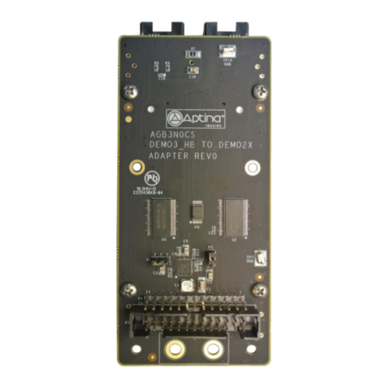
The AGB3N0CS Adapter Board is an adapter that helps connect the
Demo 3 Headboards with the Demo 2× Baseboard. Since the Demo 2×
Baseboard does not use the same connector as the Demo 3
Headboards, the AGB3N0CS provides communication between the
headboard parallel and serial connectors to communicate with the
Demo 3 Headboard's interface connection.
Features
•
Demo 2× Board Connectors
•
Voltage Selection and Operating Mode Selector
•
MIPI/HiSPi Connectors
•
Demo 3 Headboard Connector
Block Diagram
Parallel Data
16
Control
Signals
7
Master Clock
Reset
2
I
C Data
2
I
C Clock
Figure 2. Block Diagram of AGB3N0CS−GEVK
© Semiconductor Components Industries, LLC, 2015
September, 2015 − Rev. 0
Arrow.com.
Downloaded from
Power
Distribution
Parallel Data
Parallel Data
Level Shifter
16
Control
Signals
Control Signal
7
Level Shifter
Master Clock
Reset
2
I
C Data
2
I
C Buffer
2
I
C Clock
Serial Data
4
Serial Clock
EVAL BOARD USER'S MANUAL
5 V from Demo
2x Connector
Demo 2x
Baseboard
MIPI/HiSPi
Connectors
Figure 1. AGB3N0CS Evaluation Board
1
www.onsemi.com
Publication Order Number:
EVBUM2313/D
Advertisement
Table of Contents

Related Manuals for ON Semiconductor AGB3N0CS-GEVK


Summary of Contents for ON Semiconductor AGB3N0CS-GEVK
- Page 1 AGB3N0CS-GEVK AGB3N0CS Evaluation Board User's Manual Adapter Board Overview The AGB3N0CS Adapter Board is an adapter that helps connect the www.onsemi.com Demo 3 Headboards with the Demo 2× Baseboard. Since the Demo 2× Baseboard does not use the same connector as the Demo 3 EVAL BOARD USER’S MANUAL...
- Page 2 AGB3N0CS−GEVK Top View MIPI/HiSPi Connector J1 MIPI/HiSPi Connector J2 Demo 3 Headboard Connector P6 Figure 3. Top View of Adapter Board with Connectors Bottom View VDDIO Select P5 Mode Selector P1 Demo 2× Baseboard Connector P4 Demo 2× Baseboard Connector P3 Figure 4.
- Page 3 AGB3N0CS−GEVK Jumper Pin Location The jumpers on boards start with Pin 1 on the leftmost side of the pin. Grouped jumpers increase in pin size with each jumper added. Pin 1 Pins 1−4 Figure 5. Pin Locations for a Single Jumper. Pin 1 is Located at the Leftmost Side Jumper/Header Functions &...
- Page 4 AGB3N0CS−GEVK Table 2. 14-PIN DEMO 2X BASEBOARD CONNECTOR FUNCTION DESCRIPTION (P4) Name Description Comment Ground S_DATA4 Parallel Data4 Parallel Data Bit S_DATA5 Parallel Data5 Parallel Data Bit S_DATA2 Parallel Data2 Parallel Data Bit S_DATA3 Parallel Data3 Parallel Data Bit S_DATA0 Parallel Data0 Parallel Data Bit S_DATA1...
- Page 5 onsemi, , and other names, marks, and brands are registered and/or common law trademarks of Semiconductor Components Industries, LLC dba “onsemi” or its affiliates and/or subsidiaries in the United States and/or other countries. onsemi owns the rights to a number of patents, trademarks, copyrights, trade secrets, and other intellectual property. A listing of onsemi’s product/patent coverage may be accessed at www.onsemi.com/site/pdf/Patent−Marking.pdf.
Need help?
Do you have a question about the AGB3N0CS-GEVK and is the answer not in the manual?
Questions and answers