Advertisement
Quick Links
AGB2N0CS-GEVK
AGB2N0CS-GEVK
Evaluation Board
User's Manual
Adapter Board Overview
The AGB2N0CS Adapter Board helps connect Demo 2×
headboards to the Demo 3 Baseboard, the AGB1N0CS−GEVK.
The Demo 3 uses a high-bandwidth USB 3.0 interface and HDMI
connector to send sensor image data to the host computer. It supports
single/double/quad MIPI interface, dual/quad lanes of HiSPi interface,
CCP, and parallel interface. Since the Demo 2× Headboards do not use
the same connector as the Demo 3, the AGB2N0CS provides
communication between the headboard parallel and serial connectors
to communicate with the Demo 3 Baseboard interface connection.
Features
•
Demo 2× Headboard Connectors
•
Parallel Data Buffer Option
•
MIPI/HiSPi Connectors
•
Demo 3 Baseboard Connector
Block Diagram
Power
Distribution
Parallel Data
16
Line Valid
Buffer/Driver
Frame Valid
Pixel Clock
Output
Enable
Control Signals
Master Clock
I
2
I
Serial Data
Serial Clock
Figure 2. Block Diagram of AGB2N0CS−GEVK
© Semiconductor Components Industries, LLC, 2015
September, 2015 − Rev. 0
5 V from Demo 3
Connector
Parallel Data
16
Line Valid
Frame Valid
Pixel Clock
6
Reset
2
C Data
C Clock
4
EVAL BOARD USER'S MANUAL
®
Demo 2x
Headboard
MIPI/HiSPi
Connectors
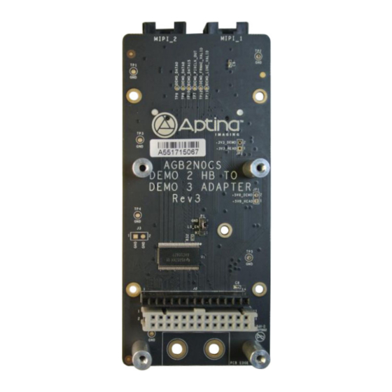
Figure 1. AGB2N0CS Evaluation Board
1
www.onsemi.com
Top View
Bottom View
Publication Order Number:
EVBUM2311/D
Advertisement

Related Manuals for ON Semiconductor AGB2N0CS-GEVK


Summary of Contents for ON Semiconductor AGB2N0CS-GEVK
- Page 1 AGB2N0CS-GEVK AGB2N0CS-GEVK Evaluation Board User's Manual Adapter Board Overview www.onsemi.com The AGB2N0CS Adapter Board helps connect Demo 2× headboards to the Demo 3 Baseboard, the AGB1N0CS−GEVK. EVAL BOARD USER’S MANUAL ® The Demo 3 uses a high-bandwidth USB 3.0 interface and HDMI connector to send sensor image data to the host computer.
- Page 2 AGB2N0CS−GEVK Top View Parallel Data Buffer Selector P1 Demo 2× Headboard Demo 2× Headboard Connector J1 Figure 3. Top View of Adapter Board with Default Jumpers, Test Pins and Connectors Bottom View MIPI/HiSPi Connector J5 MIPI/HiSPi Connector J6 Demo 3 Baseboard Connector J8 Figure 4.
- Page 3 AGB2N0CS−GEVK Jumper Pin Location The jumpers on headboards start with Pin 1 on the leftmost side of the pin. Grouped jumpers increase in pin size with each jumper added. Pin 1 Pins 1−4 Figure 5. Pin Locations for a Single Jumper. Pin 1 is Located at the Leftmost Side Jumper/Header Functions &...
- Page 4 AGB2N0CS−GEVK Table 1. 26-PIN DEMO 2X HEADBOARD CONNECTOR FUNCTION DESCRIPTION (J1) (continued) Name Description Comment Ground MCLK Master Clock Master Clock from Demo 3 Board Table 2. 14-PIN DEMO 2X HEADBOARD CONNECTOR FUNCTION DESCRIPTION (J2) Name Description Comment Ground S_DATA4 Parallel Data4 Parallel Data Bit S_DATA5...
-
Page 5: Technical Support
LIMITATIONS OF LIABILITY: ON Semiconductor shall not be liable for any special, consequential, incidental, indirect or punitive damages, including, but not limited to the costs of requalification, delay, loss of profits or goodwill, arising out of or in connection with the board, even if ON Semiconductor is advised of the possibility of such damages. In no event shall ON Semiconductor’s aggregate liability from any obligation arising out of or in connection with the board, under any theory of liability, exceed the purchase price paid for the board, if any.
Need help?
Do you have a question about the AGB2N0CS-GEVK and is the answer not in the manual?
Questions and answers