Advertisement
Quick Links
Advertisement

Related Manuals for Yetter Furrow Max 6200-070


Summary of Contents for Yetter Furrow Max 6200-070
- Page 1 OWNER’S MANUAL PART IDENTIFICATION 2565-989 10/2022 Furrow Max 6200-070, 6200-071, 6200-072, 6200-073, 6200-080 YETTER MANUFACTURING CO. Founded 1930 Colchester, IL 62326 Toll free: (800)447-5777. Fax: (309)776-3222 Website: yetterco.com E-mail: info@yetterco.com...
-
Page 2: Table Of Contents
TABLE OF CONTENTS BOLT TORQUE............... 2 FOREWORD……………………………………………………….…....3 SAFETY………………………………………………………………....4 INSTALLATION………………………………………………....... 5-13 OPERATION………………………………………………….……....14 PARTS IDENTIFICATION……………………………………...………..15-36 BOLT TORQUE Important: Over-tightening hardware can cause just as much damage as under-tightening. Tightening hardware beyond the recommended range can reduce its shock load capacity. All hardware is either Grade 5 unless otherwise noted. -
Page 3: Foreword
Important will apply to the same information as specified by note only of an immediate and Yetter Manufacturing warrants all products manufactured and sold by it against defects in material. This urgent nature. warranty being expressly limited to replacement at the factory of such parts or products as shall appear to be defective after inspection. -
Page 4: Safety
BE ALERT! YOUR SAFETY IS INVOLVED WATCH FOR THIS SYMBOL. IT POINTS OUT IMPORTANT SAFETY PRECAUTIONS. IT MEANS “ATTENTION – BE ALERT!” It is your responsibility as an owner, operator, or supervision to know and instruct everyone using this machine at the time of initial assignment and at least annually thereafter, of the proper operation, precautions, and work hazards which exist in the operation of the machine in accordance with OSHA regulations. - Page 5 INSTALLATION INSTRUCTIONS John Deere 7200/7300/1700 6200-070 STEP 1: Remove the closing wheel arm, spring and pivot bolts. Then take off the cast block bolted to the row unit. Save the two 12MM bolts holding it on. STEP 2: Using the two 12MM bolts, attach the furrow max unit to the row unit. Ensure that the closing system is straight with the row unit and torque the bolts to 92 ft/lbs.
-
Page 6: Installation
INSTALLATION INSTRUCTIONS STEP 3: Use the ½” x 3.75” pin, washers, and cotter pin to attach the spring to the disc pivot bracket. Use the shoulder bolt and locknut to attach the cast closing disc arm to the main body. Use the 3/8” x 1.25” pin and cotter pin to attach the spring to the cast arm in the 3 hole. - Page 7 INSTALLATION INSTRUCTIONS John Deere7200/7300/1700 6200-080 V-Closing wheel kit STEP 1: Remove the closing wheel arm, spring and pivot bolts. Then take off the cast block bolted to the row unit. Save the two 12MM bolts holding it on. STEP 2: Using the two 12MM bolts, attach the furrow max unit to the row unit.
- Page 8 INSTALLATION INSTRUCTIONS Kinze 3000 6200-071 STEP 1: Remove the closing wheel arm, spring and pivot bolts. Then take off the cast block bolted to the row unit by removing the 3/8” bolt STEP 2: Attach the kinze mount adapter (item 7, 8) to the main mount bracket as pictured below. Leave bolts loose at this time.
- Page 9 INSTALLATION INSTRUCTIONS STEP 3: Attach the Furrow Max to the row unit. Make sure all of the bolts are installed before you begin to tighten them. STEP 4: Use the ½” x 3.75” pin, washers, and cotter pin to attach the spring to the disc pivot bracket. Use the shoulder bolt and locknut to attach the cast closing disc arm to the main body.
- Page 10 INSTALLATION INSTRUCTIONS White 9000 6200-072 STEP 1: Remove the closing wheel arm, spring and pivot bolts. Then take off the cast block bolted to the row unit. Save the two 12MM bolts holding it on. STEP 2: Using the two 12MM bolts, attach the furrow max unit to the row unit. Ensure that the closing system is straight with the row unit and torque the bolts to 92 ft/lbs.
- Page 11 INSTALLATION INSTRUCTIONS STEP 3: Use the ½” x 3.75” pin, washers, and cotter pin to attach the spring to the disc pivot bracket. Use the shoulder bolt and locknut to attach the cast closing disc arm to the main body. Use the 3/8” x 1.25” pin and cotter pin to attach the spring to the cast arm in the 3 hole.
- Page 12 INSTALLATION INSTRUCTIONS Kinze 4900 6200-073 STEP 1: Remove the closing wheel arm, spring and pivot bolts. STEP 2: Install the Furrow max sub assembly by first putting the ½” carriage bolts through the old pivot bolt holes. Next put the 7/16” bolt through the lower hole where the old down pressure spring attached. Tighten the carriage bolts and the 7/16”...
- Page 13 STEP 3: Use the ½” x 3.75” pin, washers, and cotter pin to attach the spring to the disc pivot bracket. Use the shoulder bolt and locknut to attach the cast closing disc arm to the main body. Use the 3/8” x 1.25” pin and cotter pin to attach the spring to the cast arm in the 3 hole.
-
Page 14: Operation
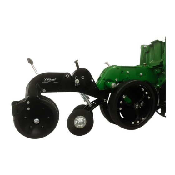
OPERATION The front closing disc need to collapse the sidewall and close the seed trench. They need to be run at or above seed depth. The front adjustment handle is for making small adjustment in down pressure. Big adjustments can be made by changing where the spring attaches to the cast spine. If the seed trench can not be collapsed, you can narrow up the spacing on the dual closing disc by changing the spacers. -
Page 15: Parts Identification
PART IDENTIFICATION 6200-070 John Deere 7200/7300/1700... - Page 17 PART IDENTIFICATION 6200-071 Kinze 3000...
- Page 19 PART IDENTIFICATION 6200-072 White 9000...
- Page 21 PART IDENTIFICATION 6200-073 Kinze 4000...
- Page 23 PART IDENTIFICATION John Deere7200/7300/1700 6200-080 V-Closing wheel kit...
- Page 25 PART IDENTIFICATION 6000-013A 8” Serrated...
- Page 26 PART IDENTIFICATION 6000-017 8” Smooth...
- Page 27 PART IDENTIFICATION 6200-085...
- Page 28 PART IDENTIFICATION 6200-182...
- Page 29 PART IDENTIFICATION 6200-185...
- Page 30 PART IDENTIFICATION 6200-187...
- Page 31 PART IDENTIFICATION 6200-189...
- Page 32 PART IDENTIFICATION 6200-192...
- Page 35 NOTES:...
- Page 36 2565-989 – 10/2022...
Need help?
Do you have a question about the Furrow Max 6200-070 and is the answer not in the manual?
Questions and answers