
Subscribe to Our Youtube Channel
Related Manuals for Kramer VP-1608


Summary of Contents for Kramer VP-1608
- Page 1 K R A ME R E LE CT R O N IC S L T D . USER MANUAL MODEL: VP-1608 16x8 RGBHV/Balanced Audio Matrix P/N: 2900-001608 Rev 5...
-
Page 3: Table Of Contents
Contents Introduction Getting Started Achieving the Best Performance Overview Defining the VP-1608 16x8 RGBHV/Balanced Audio Matrix Installing in a Rack Connecting a Single VP-1608 Connecting a Balanced/Unbalanced Stereo Audio Input/Output Connecting to the VP-1608 via RS-232 Connecting a PC or Controller to the RS-485 Port... - Page 4 Figure 8: Control Configuration via RS-232 and RS-485 Figure 9: DIP-Switch Setup on a Single Machine Figure 10: VP-1608 Unit Characteristics Figure 11: VP-1608 Underside Flash Program Switches Set for Upgrade Figure 12: Splash Screen Figure 13: Atmel – Flip Window...
-
Page 5: Introduction
Introduction Welcome to Kramer Electronics! Since 1981, Kramer Electronics has been providing a world of unique, creative, and affordable solutions to the vast range of problems that confront the video, audio, presentation, and broadcasting professional on a daily basis. In recent years, we have redesigned and upgraded... -
Page 6: Getting Started
Do not secure the cables in tight bundles or roll the slack into tight coils • Avoid interference from neighboring electrical appliances that may adversely influence signal quality • Position your Kramer VP-1608 away from moisture, excessive sunlight and dust VP-1608 - Getting Started... -
Page 7: Overview
Overview The VP-1608 16x8 RGBHV/Balanced Audio Matrix is a true matrix switcher, routing any input to any or all outputs. The VP-1608 includes 16 input and 8 output selector buttons. The unit features: • A bandwidth of 400MHz (fully loaded) for RGB signals •... -
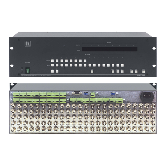
Page 8: Figure 1: Vp-1608 16X8 Rgbhv/Balanced Audio Matrix Front Panel
Figure 1: VP-1608 16x8 RGBHV/Balanced Audio Matrix Front Panel VP-1608 - Overview... - Page 9 Feature Function IR Receiver The LED is illuminated when receiving signals from the Kramer Infra-red remote control transmitter POWER Switch Illuminated switch supplying power to the unit Select the output to which the input is switched (from 1 to 8)
-
Page 10: Figure 2: Vp-1608 16X8 Rgbhv/Balanced Audio Matrix Rear Panel
Figure 2: VP-1608 16x8 RGBHV/Balanced Audio Matrix Rear Panel Feature Function RS-232 9-pin D-sub (F) Connector Connects to the PC or other Serial Controller Setup DIP-switches DIPS 1, 2, and 3 for setup of the Machine #; DIP 4 for RS-485 termination... -
Page 11: Figure 3: Vp-1608 Underside Flash Program Switches
AUDIO INPUTS Terminal Block Connectors Connect to the audio sources (from 1 to 16) AUDIO OUT Terminal Block Connectors Connect to the audio acceptors (from 1 to 8) Figure 3: VP-1608 Underside Flash Program Switches Feature Function Flash Program Switch 1... -
Page 12: Installing In A Rack
Installing in a Rack This section provides instructions for rack mounting the unit. VP-1608 - Installing in a Rack... -
Page 13: Connecting A Single Vp-1608
To connect a single VP-1608 16x8 RGBHV/Balanced Audio Matrix as illustrated in Figure 4, do the following: To connect up to 8 VP-1608 units to a PC or other RS-232/RS-485 controller (see Section 1. Connect up to 16 RGBHV sources (such as RGBHV graphics sources) to the RGBHV INPUT BNC connectors. -
Page 14: Figure 4: Connecting The Vp-1608
Figure 4: Connecting the VP-1608 VP-1608 - Connecting a Single VP-1608... -
Page 15: Connecting A Balanced/Unbalanced Stereo Audio Input/Output
RS-232 9-pin D-sub port on your PC Connecting a PC or Controller to the RS-485 Port You can operate the VP-1608 via the RS-485 port from a distance of up to 1200m (3900ft) using any device equipped with an RS-485 port (for example, a PC). For successful communication, you must set the RS-485 machine number and bus termination. -
Page 16: Setting The Machine # Dip-Switches
The MACHINE # determines the address of a VP-1608 unit when several VP-1608 units are controlled by a PC or serial controller. Set the MACHINE # on a VP-1608 unit via DIPS 1, 2, and 3 (DIP 4 is for RS-485 termination), according to the... -
Page 17: Setting The Delay Dip-Switches
To achieve clean transitions when switching between non-genlocked sources, set the delay time—ranging from 0sec to 3.5sec in increments of 0.5sec—via the DELAY DIP-switches, as shown in the following table. The VP-1608 unit is shipped from the factory set with no delay (0sec). -
Page 18: Connecting Multiple Vp-1608 Units
Connecting Multiple VP-1608 Units You can connect up to eight single VP-1608 units from a PC or serial controller via RS-232 and RS-485 (see Section 6.1), or up to seven single VP-1608 units via RS-485 (see Section 6.2). To connect a single VP-1608 unit to a PC or other RS-232 controller, see Section 5.2. -
Page 19: Connecting Via An Rs-485 Controller
Figure 8: Control Configuration via RS-232 and RS-485 Connecting via an RS-485 Controller To connect up to seven single VP-1608 units via an RS-485 controller, for example, a PC (equipped with an RS-485 interface), do the following: Always switch off the power to each device before connecting it to your VP-1608. - Page 20 VP-1608 unit (see Section 5.3). 3. Terminate the RS-485 line on both the PC and on the last VP-1608 unit (set DIP 4 to ON). 4. Connect the RS-485 ports from the PC to the RS-485 ports on each of the VP-1608 units, as follows: Connect the “A”...
-
Page 21: Operating Your Vp-1608 16X8 Rgbhv/Balanced Audio Matrix
7.8) Using the Audio-Follow-Video or Breakaway Option By default, the VP-1608 is setup for use as a single machine. This means that it is a 16x8 RGBHV/Balanced Audio Matrix (in audio-follow-video mode), with all setups empty and each input connected to its corresponding output (for example, input 1 to output 1). -
Page 22: Switching Out-In Combinations
2. Press an INPUT SELECTOR button. The selected input switches to the selected output. For example, press the ALL button and then INPUT SELECTOR button # 2 to connect input # 2 to all the outputs. VP-1608 - Operating Your VP-1608 16x8 RGBHV/Balanced Audio Matrix... -
Page 23: Confirming Settings
Choose to work in the AT ONCE or the CONFIRM mode, as explained in Section 7.3.1. When the VP-1608 operates in the AT ONCE mode, pressing an OUT-IN combination implements the switch immediately. In the CONFIRM mode, the TAKE button must be pressed to authorize the switch. -
Page 24: Storing/Recalling Input/Output Configurations
16 inputs, and the audio gain level for each of the eight outputs. 7.4.1 Storing an Input/Output Configuration To store the current status in memory, do the following: 1. Press the STO button. The STO button flashes. VP-1608 - Operating Your VP-1608 16x8 RGBHV/Balanced Audio Matrix... - Page 25 The memory recalls the stored data from that reference. To view the saved input/output configurations, set the VP-1608 to the CONFIRM mode and manually scan all the input/output configurations. Press RCL followed by an INPUT SELECTOR button to display a configuration. To recall this configuration, press TAKE to select it.
-
Page 26: Adjusting The Audio Gain Control
VP-1608. Unlocking releases the protection mechanism. Nevertheless, even though the front panel is locked you can still operate via RS-232 or RS-485 serial (remote controller or PC), as well as via the Kramer RC-IR3 Infrared Remote Control Transmitter. To lock the VP-1608: •... -
Page 27: Displaying Unit Characteristics
7.7.1 Resetting to the Current Status You can reset the VP-1608 unit to the current status (reloads the current setup) To reset a VP-1608 unit to the current status, do the following: • Press INPUT buttons 1 and 5 simultaneously for 3 seconds... -
Page 28: Flash Memory Upgrade
Before installing the latest Kramer firmware version on a VP-1608 unit, do the following: 1. Connect the RS-232 9-pin D-sub (F) rear panel port on the VP-1608 to the RS-232 9-pin D-sub (F) COM port on your PC (see Section 5.1) with a 9-wire... -
Page 29: Upgrading The Firmware
Figure 11: VP-1608 Underside Flash Program Switches Set for Upgrade Upgrading the Firmware To upgrade the firmware, follow these steps: 1. Double-click the desktop icon: “Shortcut to FLIP.EXE”. The Splash screen appears as follows: Figure 12: Splash Screen 2. After a few seconds, the Splash screen is replaced by the “Atmel – Flip”... -
Page 30: Figure 13: Atmel - Flip Window
Device menu, or press the integrated circuit icon in the upper right corner of the window). The “Device Selection” window appears: Figure 14: Device Selection Window 4. Click the button next to the name of the device and select from the list: AT89C51RD2. VP-1608 - Flash Memory Upgrade... -
Page 31: Figure 15: Device Selection Window
AT89C51RD2 T89C51RD2 Figure 15: Device Selection Window 5. Click OK and select “Load Hex” from the File menu. Figure 16: Loading the Hex VP-1608 - Flash Memory Upgrade... -
Page 32: Figure 17: Rs-232 Window
6. The Open File window opens. Select the correct HEX file that contains the updated version of the firmware for the VP-1608 (for example 1608M_V1p2.hex) and click Open. 7. Press the keyboard shortcut key F3 (or select the “Communication/RS232” command from the Settings menu, or press the keys: Alt- SCR). -
Page 33: Figure 19: Atmel - Flip Window (Operation Completed)
12. Set both the underside switches: Flash Program switch 1 and Flash Program switch 2 (see Figure 3) to Normal. 13. Connect the power on the VP-1608. Upon initialization, the new VP-1608 software version shows in the INPUT STATUS 7-segment Display. VP-1608 - Flash Memory Upgrade... -
Page 34: Technical Specifications
10% to 90%, RHL non-condensing DIMENSIONS: 19" x 7" x 3U W, D, H, rack mountable WEIGHT: 5.5kg, (12.2lbs) approx. ACCESSORIES: Power cord, Windows®-based Kramer control software, IR remote control Specifications are subject to change without notice at http://www.kramerelectronics.com VP-1608 - Technical Specifications... -
Page 35: Table Of Hex Codes For Serial Communication
Switching Audio Channels IN 1 IN 2 IN 3 IN 4 IN 5 IN 6 IN 7 IN 8 IN 9 IN 10 IN 11 IN 12 IN 13 IN 14 VP-1608 - Table of Hex Codes for Serial Communication... - Page 36 Switching Video Channels Switching Audio Channels IN 15 IN 16 VP-1608 - Table of Hex Codes for Serial Communication...
-
Page 37: Hex Tables For Audio Input/Output Gain Control
“audio inputs gain adjustment” mode continues until instruction 42 changes to the “audio outputs gain adjustment” mode: The next table lists the hex values for the audio gain control of the 16 inputs: VP-1608 - Hex Tables for Audio Input/Output Gain Control... - Page 38 INPUTS VP-1608 - Hex Tables for Audio Input/Output Gain Control...
-
Page 39: Hex Tables For Audio Output Gain Control
“audio outputs gain adjustment” mode continues until instruction 42 changes to the “audio inputs gain adjustment” mode: The next table lists the hex values for the audio gain control of the eight outputs: VP-1608 - Hex Tables for Audio Input/Output Gain Control... - Page 40 OUTPUTS *In the Mute state, the audio output is physically disconnected from the input VP-1608 - Hex Tables for Audio Input/Output Gain Control...
-
Page 41: Kramer Protocol 2000
Kramer Protocol 2000 The Kramer Protocol 2-000 RS-232/RS-485 communication uses four bytes of information as defined below. DESTINATION INSTRUCTION 1st byte INPUT 2nd byte OUTPUT 3rd byte MACHINE NUMBER 4th byte 1st BYTE: Bit 7 – Defined as 0. D – “DESTINATION”: 0 - for sending information to the switchers (from the PC);... - Page 42 I0 - 0=input; 1=output 1 - Bass INSTRUCTIONS 22, 24, 25 I1 - Left 2 - Treble I2 - Right 3 - Midrange 57 SET AUTO-SAVE I3 - no save 12, 2 I4 - auto-save VP-1608 - Kramer Protocol 2000...
- Page 43 Reception of this code by the switcher is not valid. NOTE 11 – For machines where the video and/or audio gain is programmable. VP-1608 - Kramer Protocol 2000...
- Page 44 NOTE 23 – Further information needed in instructions 21, 22, 25 and 26, is sent using instruction 42 – which is sent prior to the instruction. For example, to request the audio gain value of right input # 9, send hex codes and then send HEX codes VP-1608 - Kramer Protocol 2000...
- Page 46 " " P/N: 2900- 001608 Rev: 5...
Need help?
Do you have a question about the VP-1608 and is the answer not in the manual?
Questions and answers