Table of Contents
Advertisement
Quick Links
www.ti.com
User's Guide
Dual-Mode Bluetooth
The CC2564MODNEM is a low-cost evaluation board for TI's CC2564MODN device. The evaluation board
is designed to plug-in to additional TI hardware development kits, such as MSP430 or TM4C microcontroller
development platforms, to create a complete evaluation platform. This guide is designed to help users quickly
get started with the CC2564MODNEM board and integrate it with multiple platforms for prototyping Bluetooth
applications.
The CC2564MODN device is a complete Bluetooth BR/EDR/LE HCI solution based on TI's CC2564B dual-mode
Bluetooth single-chip device, which reduces design effort and enables fast time to market. The CC2564MODN
device includes TI's seventh-generation Bluetooth core and provides a product-proven solution that is Bluetooth
4.1 compliant. The CC2564MODN device provides best-in-class RF performance with a transmit power and
receive sensitivity that provides range of about 2 times compared to other Bluetooth Low Energy only solutions.
1
Introduction.............................................................................................................................................................................3
2
Features...................................................................................................................................................................................3
3 CC2564MODNEM Board Applications..................................................................................................................................
Contents.............................................................................................................................................................................5
6
Requirements..........................................................................................................................................................................5
7
Overview..................................................................................................................................................................................7
Description.............................................................................................................................................................9
8.1 Overview............................................................................................................................................................................
8.2
Connectors.........................................................................................................................................................................9
8.3 Board Configurations.......................................................................................................................................................
9 Software Tools......................................................................................................................................................................
9.1 TI Dual-Mode Bluetooth Stack.........................................................................................................................................
9.2 TI Dual-Mode Bluetooth Service Pack for CC256x..........................................................................................................
9.3 Bluetooth Hardware Evaluation Tool................................................................................................................................
10 Manual Information to the End User.................................................................................................................................
Function....................................................................................................................................................................18
History..................................................................................................................................................................22
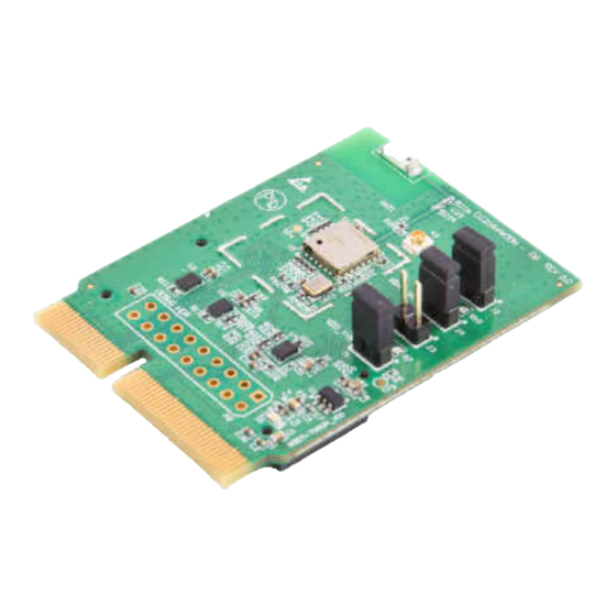
Figure 4-1. CC2564MODNEM Board..........................................................................................................................................
Figure 6-3. Other MCU Hardware Setup Examples....................................................................................................................
Figure 8-1. CC2564MODNEM Block Diagram............................................................................................................................
Figure 8-2. Jumper Configuration..............................................................................................................................................
Figure 8-3. Jumper Configuration..............................................................................................................................................
Figure 8-4. Clock Input..............................................................................................................................................................
Figure 8-5. UART Default Configuration....................................................................................................................................
Figure 8-6. UART COM Connector Configuration.....................................................................................................................
Figure 8-7. PCM Connector Configuration................................................................................................................................
SWRU390A - AUGUST 2014 - REVISED AUGUST 2021
Submit Document Feedback
®
CC2564 Module Evaluation Board
ABSTRACT
Table of Contents
Board...............................................................................................................................4
Statement...........................................................................................................................18
Statement......................................................................................................................................21
List of Figures
Examples.........................................................................................................................6
Examples.............................................................................................................................6
Overview.................................................................................................................7
Connectors..............................................................................................................8
Copyright © 2021 Texas Instruments Incorporated
Dual-Mode Bluetooth
®
CC2564 Module Evaluation Board
Table of Contents
4
9
12
17
17
17
17
18
4
6
9
12
13
13
14
14
15
1
Advertisement
Table of Contents

Related Manuals for Texas Instruments CC2564MODN


Summary of Contents for Texas Instruments CC2564MODN
-
Page 1: Table Of Contents
CC2564MODNEM board and integrate it with multiple platforms for prototyping Bluetooth applications. The CC2564MODN device is a complete Bluetooth BR/EDR/LE HCI solution based on TI's CC2564B dual-mode Bluetooth single-chip device, which reduces design effort and enables fast time to market. The CC2564MODN device includes TI's seventh-generation Bluetooth core and provides a product-proven solution that is Bluetooth 4.1 compliant. - Page 2 ® are registered trademarks of Bluetooth SIG. All trademarks are the property of their respective owners. ® Dual-Mode Bluetooth CC2564 Module Evaluation Board SWRU390A – AUGUST 2014 – REVISED AUGUST 2021 Submit Document Feedback Copyright © 2021 Texas Instruments Incorporated...
-
Page 3: Introduction
Introduction 1 Introduction The CC2564MODNEM evaluation board contains the CC2564MODN device. TI intends the board for evaluation and design purposes. For a complete evaluation solution, the CC2564MODNEM board plugs directly into the following TI hardware development kits: • MSP-EXP430F5529 •... -
Page 4: Cc2564Modnem Board Applications
Module information and capabilities, including pin descriptions, available software, and tools, enhance your out-of-box experience. Figure 4-1. CC2564MODNEM Board ® Dual-Mode Bluetooth CC2564 Module Evaluation Board SWRU390A – AUGUST 2014 – REVISED AUGUST 2021 Submit Document Feedback Copyright © 2021 Texas Instruments Incorporated... -
Page 5: Kit Contents
IDE Versions – Platform Dependent – Code Composer Studio (CCS) – IAR 7.2/7.3 for ARM – Keil µVision 4.70.0.0 ® SWRU390A – AUGUST 2014 – REVISED AUGUST 2021 Dual-Mode Bluetooth CC2564 Module Evaluation Board Submit Document Feedback Copyright © 2021 Texas Instruments Incorporated... -
Page 6: Figure 6-1. Msp430 Hardware Setup Examples
Figure 6-1. MSP430 Hardware Setup Examples Figure 6-2. TM4C Hardware Setup Examples Figure 6-3. Other MCU Hardware Setup Examples ® Dual-Mode Bluetooth CC2564 Module Evaluation Board SWRU390A – AUGUST 2014 – REVISED AUGUST 2021 Submit Document Feedback Copyright © 2021 Texas Instruments Incorporated... -
Page 7: Overview
Overview 7 Overview The CC2564MODNEM board is the development environment for the CC2564MODN module and plugs directly into TI's MSP430 and TM4C experimenter boards with EM connectors that simplify prototype wiring and field trials. This module is based upon TI’s CC2564B device and uses a host controller interface (HCI); this module is a cost-effective and flexible way to implement a Bluetooth network. -
Page 8: Figure 7-2. Cc2564Modnem Board Back
Overview www.ti.com Figure 7-2. CC2564MODNEM Board Back Connectors ® Dual-Mode Bluetooth CC2564 Module Evaluation Board SWRU390A – AUGUST 2014 – REVISED AUGUST 2021 Submit Document Feedback Copyright © 2021 Texas Instruments Incorporated... -
Page 9: Hardware Description
EM (default) • The connectors can supply power to the CC2564MODN through either VBAT_EDGE or VBAT_MCU. For the EM connector, the signals are controlled through level shifters. The hardware can be configured and modified to use the slow clock from the connectors. The third connector, the debug header, can be used for testing. The I/Os of the EM connector are at 3.3 V. - Page 10 EM Adaptor Assignment Pin Number EM Adaptor Assignment 3.3V MODULE_AUDIO_DATA_OUT 3.3V MODULE_AUDIO_DATA_IN MODULE_AUDIO_FSINK MODULE_AUDIO_CLK MODULE_UART_RTS nSHUTD ® Dual-Mode Bluetooth CC2564 Module Evaluation Board SWRU390A – AUGUST 2014 – REVISED AUGUST 2021 Submit Document Feedback Copyright © 2021 Texas Instruments Incorporated...
- Page 11 EM Adapter Pin Assignment VBAT VIO_HOST AUD_FSYNC_1V8 AUD_CLK_1V8 AUD_OUT_1V8 AUD_IN_1V8 CLK_REQ_OUT_1V8 SLOW_CLK_EDGE HCI_TX_1V8 HCI_RX_1V8 HCI_CTS_1V8 HCI_RTS_1V8 TX_DEBUG_1V8 nSHUTDOWN_1V8 VDD_1V8 ® SWRU390A – AUGUST 2014 – REVISED AUGUST 2021 Dual-Mode Bluetooth CC2564 Module Evaluation Board Submit Document Feedback Copyright © 2021 Texas Instruments Incorporated...
-
Page 12: Board Configurations
8.3.2 RF Interface The board can be configured to route the radio frequency (RF) output from the CC2564MODN to the on-board chip antenna or the on-board U.FL connector. This configuration is done by placing the resistor in either R29 or R30 position which has negligible resistance of 0 Ω. -
Page 13: Figure 8-3. Jumper Configuration
The slow clock can come from an internal or external source. The CC2564MODNEM lets you place the slow clock on the board (the default setting) or source it from an external source. The CC2564MODN connects to the SLOW_CLK_IN and can be a digital signal in the range of 0 V to 1.8 V. The frequency accuracy of the slow clock must be 32.768 kHz + –250 ppm for Bluetooth use (according to the Bluetooth specification). -
Page 14: Figure 8-5. Uart Default Configuration
(Default) Level UART UART Connector Shifters UART CC2564MODN UART Connector Figure 8-6. UART COM Connector Configuration ® Dual-Mode Bluetooth CC2564 Module Evaluation Board SWRU390A – AUGUST 2014 – REVISED AUGUST 2021 Submit Document Feedback Copyright © 2021 Texas Instruments Incorporated... -
Page 15: Figure 8-7. Pcm Connector Configuration
Hardware Description 8.3.5 PCM Configuration For voice and assisted audio features, the PCM signals from CC2564MODN (master) must be connected to an external audio host (slave). This relationship signifies that the CC2564MODN board provides the FSYNC and slow clock signals to the codec. - Page 16 8.3.5.1 EM Configuration The EM connector allows configuration of the CC2564MODN as either the master or slave. The default configuration is a master role for the module through the EM connectors. To change the direction of the PCM so the module is configured as the slave, do the following: 1.
-
Page 17: Software Tools
TI. The program is an intuitive, user-friendly tool to test TI's Bluetooth chips including this CC256xQFNEM board. This tool tests RF performance and modifies the service packs of our Bluetooth chips. ® SWRU390A – AUGUST 2014 – REVISED AUGUST 2021 Dual-Mode Bluetooth CC2564 Module Evaluation Board Submit Document Feedback Copyright © 2021 Texas Instruments Incorporated... -
Page 18: Manual Information To The End User
RF module in the user's manual of the end product. The end user manual must include all require regulatory information and warnings as shown in this manual. 10.1 RF Function The CC2564MODN is a dual-mode Bluetooth HCI module. Note The maximum RF power transmitted in each band is 10 dBm. - Page 19 A separate approval is required for all other operating configurations, including different antenna configurations. 10.2.3 Anatel Certification Label Figure 10-1 shows the full Anatel certification label for the CC2564MODN. Figure 10-1. Anatel Certification Label ® SWRU390A – AUGUST 2014 – REVISED AUGUST 2021...
- Page 20 – The closest separation among all simultaneous transmitting antennas is greater than 20 cm. ® Dual-Mode Bluetooth CC2564 Module Evaluation Board SWRU390A – AUGUST 2014 – REVISED AUGUST 2021 Submit Document Feedback Copyright © 2021 Texas Instruments Incorporated...
-
Page 21: Eu Certification And Statement
20-cm separation distance to the user. 10.3.2 Simplified DoC Statement 10.3.2.1 CC2564MODN Module Hereby, Texas Instruments declares that the radio equipment type CC2564MODN is in compliance with Directive 2014/53/EU. The full text of the EU declaration of conformity is available here. -
Page 22: Revision History
Updated formatting and organization to match current TI standards..............0 • Added Section 10 through Section 10.3.5 ....................... ® Dual-Mode Bluetooth CC2564 Module Evaluation Board SWRU390A – AUGUST 2014 – REVISED AUGUST 2021 Submit Document Feedback Copyright © 2021 Texas Instruments Incorporated... - Page 23 TI products. TI’s provision of these resources does not expand or otherwise alter TI’s applicable warranties or warranty disclaimers for TI products. TI objects to and rejects any additional or different terms you may have proposed. IMPORTANT NOTICE Mailing Address: Texas Instruments, Post Office Box 655303, Dallas, Texas 75265 Copyright © 2022, Texas Instruments Incorporated...
Need help?
Do you have a question about the CC2564MODN and is the answer not in the manual?
Questions and answers